EP0132876A1 - Hottes aspirantes de fumées secondaires dans les aciéries et les fonderies - Google Patents
Hottes aspirantes de fumées secondaires dans les aciéries et les fonderies Download PDFInfo
- Publication number
- EP0132876A1 EP0132876A1 EP84201004A EP84201004A EP0132876A1 EP 0132876 A1 EP0132876 A1 EP 0132876A1 EP 84201004 A EP84201004 A EP 84201004A EP 84201004 A EP84201004 A EP 84201004A EP 0132876 A1 EP0132876 A1 EP 0132876A1
- Authority
- EP
- European Patent Office
- Prior art keywords
- hoods
- fumes
- aspiration
- foundries
- steel mills
- Prior art date
- Legal status (The legal status is an assumption and is not a legal conclusion. Google has not performed a legal analysis and makes no representation as to the accuracy of the status listed.)
- Granted
Links
- 239000003517 fume Substances 0.000 title claims abstract description 64
- 229910000831 Steel Inorganic materials 0.000 title claims abstract description 21
- 239000010959 steel Substances 0.000 title claims abstract description 21
- 238000003723 Smelting Methods 0.000 claims abstract description 11
- 230000001105 regulatory effect Effects 0.000 claims 1
- 238000005266 casting Methods 0.000 description 8
- 238000009434 installation Methods 0.000 description 7
- 238000004519 manufacturing process Methods 0.000 description 2
- 238000007789 sealing Methods 0.000 description 2
- 238000010891 electric arc Methods 0.000 description 1
Images
Classifications
-
- B—PERFORMING OPERATIONS; TRANSPORTING
- B22—CASTING; POWDER METALLURGY
- B22D—CASTING OF METALS; CASTING OF OTHER SUBSTANCES BY THE SAME PROCESSES OR DEVICES
- B22D45/00—Equipment for casting, not otherwise provided for
- B22D45/005—Evacuation of fumes, dust or waste gases during manipulations in the foundry
-
- C—CHEMISTRY; METALLURGY
- C21—METALLURGY OF IRON
- C21C—PROCESSING OF PIG-IRON, e.g. REFINING, MANUFACTURE OF WROUGHT-IRON OR STEEL; TREATMENT IN MOLTEN STATE OF FERROUS ALLOYS
- C21C5/00—Manufacture of carbon-steel, e.g. plain mild steel, medium carbon steel or cast steel or stainless steel
- C21C5/28—Manufacture of steel in the converter
- C21C5/38—Removal of waste gases or dust
-
- F—MECHANICAL ENGINEERING; LIGHTING; HEATING; WEAPONS; BLASTING
- F27—FURNACES; KILNS; OVENS; RETORTS
- F27B—FURNACES, KILNS, OVENS OR RETORTS IN GENERAL; OPEN SINTERING OR LIKE APPARATUS
- F27B14/00—Crucible or pot furnaces
- F27B14/08—Details specially adapted for crucible or pot furnaces
-
- F—MECHANICAL ENGINEERING; LIGHTING; HEATING; WEAPONS; BLASTING
- F27—FURNACES; KILNS; OVENS; RETORTS
- F27D—DETAILS OR ACCESSORIES OF FURNACES, KILNS, OVENS OR RETORTS, IN SO FAR AS THEY ARE OF KINDS OCCURRING IN MORE THAN ONE KIND OF FURNACE
- F27D17/00—Arrangements for using waste heat; Arrangements for using, or disposing of, waste gases
- F27D17/30—Arrangements for extraction or collection of waste gases; Hoods therefor
- F27D17/304—Arrangements for extraction or collection of waste gases; Hoods therefor specially adapted for electric arc furnaces
-
- F—MECHANICAL ENGINEERING; LIGHTING; HEATING; WEAPONS; BLASTING
- F27—FURNACES; KILNS; OVENS; RETORTS
- F27B—FURNACES, KILNS, OVENS OR RETORTS IN GENERAL; OPEN SINTERING OR LIKE APPARATUS
- F27B14/00—Crucible or pot furnaces
- F27B14/08—Details specially adapted for crucible or pot furnaces
- F27B14/0806—Charging or discharging devices
-
- F—MECHANICAL ENGINEERING; LIGHTING; HEATING; WEAPONS; BLASTING
- F27—FURNACES; KILNS; OVENS; RETORTS
- F27B—FURNACES, KILNS, OVENS OR RETORTS IN GENERAL; OPEN SINTERING OR LIKE APPARATUS
- F27B14/00—Crucible or pot furnaces
- F27B14/08—Details specially adapted for crucible or pot furnaces
- F27B2014/0825—Crucible or pot support
- F27B2014/0831—Support or means for the transport of crucibles
Definitions
- This invention concerns improvements to hoods for aspiration of secondary fumes in steel mills and foundries.
- the invention also concerns hoods for aspiration of secondary fumes in steel mills and foundries which adopt such improvements.
- the invention concerns, in particular, hoods for aspiration of secondary fumes which are of the type described in European Patent Application published under No.0063669 (priority: IT 83366 A/81) in the name of the present applicant.
- US 3,806,622 discloses an installation cooperating with an arc furnace and enclosing it completely.
- This installation envisages the arc furnace as being positioned on wheels and being movable but does not visualise the possibility of acting with a bridge crane except for moving the furnace itself.
- US 3,938,788 is also known and discloses an installation enclosing an arc furnace but cooperating with a crane ' at the same time.
- the lengthwise trolleys of the crane cooperate with movable panels which serve to close and plug appropriate openings made in the installation itself.
- This type of crane is substantially stationary and has its trolleys able to move along the crane itself.
- DT OS 2.511.387 is also known and discloses once more substantially the teaching of US 3,938,788.
- US 4,088,824 discloses an integral installation which, however, envisages a movable ladle beneath it.
- FR 2.381.107 discloses a box-like embodiment of a complex type, which, like the other cited installations, concerns only the furnace.
- EP-A-0006084 discloses an embodiment in which a hood is solidly fixed to the trolley of a bridge crane and can move together with that trolley. This hood can cooperate with a stationary aspiration duct.
- the invention is restricted to applications to metallurgical vessels such as crucibles, ladles, etc., since the trolley mentioned cannot bear hoods of great sizes, such as those needed to collect fumes produced by electric arc furnaces.
- EP-A-0003357 teaches a system in which the furnace is shut within an enclosure formed with two casings which can be opened. These casings are opened for the entry and exit of the charging or casting vessel. The collection of fumes while these casings are opened is entrusted to a hood solidly fixed to the bridge crane, and this hood can be placed so as to correspond and cooperate with a stationary aspiration duct.
- This system entails various drawbacks and shortcomings.
- a first drawback lies in the fact that owing to the great distance between the vessel, or furnace, and the hood the flow of air aspirated is of necessity considerable.
- Another drawback consists of the absence of sealing elements, in the lower part of the hood, which would be able to prevent the exit of fumes from the side of entry of the cables.
- the cited patent has a system of closure of the hood by means of a movable portion solidly fixed to the trolley.
- Patent DE-B-1.228.287 teaches a system with a hood of modest dimensions positioned immediately above a vessel, such as a ladle or crucible, and able to move with that vessel. Owing to its dimensions and positioning this hood cannot be very efficient, bearing in mind the fact that the flow of fumes to be aspirated has a high upwards speed owing to the high temperature. As a result the flow to be aspirated is very great. Moreover, the invention cannot be applied to the collection of fumes produced by a smelting furnace.
- DE-B-1.217.028 discloses an embodiment suitable only for vessels of small sizes, the embodiment not being applicable to smelting furnaces.
- US-A-2,923,227 teaches a system like the two preceding systems and applicable to small metallurgical vessels which are being moved.
- the duct is positioned lengthwise allows the .duct to be located in the middle between two bays of a shed so as to serve two hoods or sets of hoods placed on opposite sides of the duct.. In this way it is possible to serve plants located on the two sides of the duct in one and the other bays respectively, the plants being served by two separate bridge cranes.
- hoods can move with their bridge crane and comprise means to close the openings for the movement of the trolley and the cables bearing the charging or casting vessels. Moreover, these hoods comprise specific means suitable for connection, possibly with the interposition of sealing means, to the stationary inlets in the lengthwise aspiration duct.
- Another purpose of the invention is to provide means which enable a certain collection of fumes to be carried out even when the movable hoods together with the relative bridge crane are not positioned in correspondence with their working zone.
- the improvements of the invention can be applied not only in the case of hoods serving furnaces not shut within a soundproof enclosure but also in the case of furnaces shut within a soundproof enclosure.
- the hood consists of two parts, of which one can move together with a bridge crane, whereas the other part, also called the “exhaust collector”, is positioned above and is stationary and solidly fixed to the lengthwise aspiration duct.
- the exhaust collector When the hood is in its working position, the exhaust collector forms the plurality of the upper part of the hood.
- the collector When the hood is absent from its working position, the collector stays in position above the zone producing the fumes and thus ensures a given collection of fumes at all times. The purpose of this is to ensure better conditions within the production sheds where the furnaces or other metallurgical vessels are located.
- Shutter means or their equivalent may be positioned between the exhaust collector and the aspiration duct so as to regulate the flow aspirated or to shut off the aspiration.
- the invention envisages the ability to employ curtains or other flexible systems or systems which can be lowered.
- the purpose of such curtains is to extend the edge for the starting of collection of fumes as far downwards as possible and therefore as near as possible to the source of fumes.
- curtain means or screen means which can be lowered and raised achieves the purpose of a reduced overall vertical size of the hood when the latter is not in its working position.
- Such reduced overall size obviates collisions with other structures which may be located in the sheds, such as the transformer supplying an arc furnace, for instance, when the hoods are moved.
- hoods for aspiration of secondary fumes in steel mills and foundries which hoods are suitable to cooperate with smelting furnaces, converters, crucibles, etc. for the aspiration of fumes emitted by the same and comprise:
- the invention is also embodied with hoods for aspiration of secondary fumes in steel mills and foundries, which hoods are suitable to cooperate with smelting furnaces, converters, crucibles, etc. for the aspiration of fumes emitted by the same and adopt the above improvements.
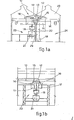
- improved hoods 10 comprise a lower portion 11 which is solidly fixed to a bridge crane and within which a charging trolley 15 can enter.
- the lower portion 11 comprises doors or other means 16-17 to close the openings required for the passage of the charging trolley 15 and of cables bearing a charging skip 18 or ladle 19.
- the upper portion of the hoods consists, instead, of a stationary exhaust collector 12 communicating with a lengthwise duct 13 positioned in this instance on the centre line between two bays of a shed 20.
- a collection surface provided by the plan section of the exhaust collector 12 itself is always positioned above a furnace 21 or vessel from which the fumes are emitted.
- seal means can be of various types and can consist, for instance, of flexible skirts or other equivalent means which can be provided on the collector 12 or on the movable portion 11 of the hood 10.
- One or more movable curtains 22 arranged on one or more sides of the hood 10 can be envisaged in the lower part of the movable portion 11 of the hood 10 (see the lines of dashes in Fig.la).
- Movement of the curtains 22 may possibly be controlled automatically, for instance by being governed by the position of the movable portion 11 and therefore of the bridge crane 14 in relation to a charging zone 23 or casting zone 24.
- the curtains 22 can be raised advantageously in this way when the lower portion 11 of the hood 10 is not situated -in correspondence with such charging zone 23 or casting zone 24, so that the curtains 22 will not come into contact with other structures inside the shed 20.
- the curtains 22 can be embodied so as to cooperate with stationary structures of the shed 20, such as the upright columns 29, for example. In this way it will not be necessary for the curtains 22 to be movable or adjustable, for they will be cooperating with the lower portion 11 of the hood 10 only in the working position of the hoods 10 themselves.
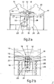
- Figs.2 show a variant relating to the application of the improvements of the invention to a furnace 21 provided with a soundproof enclosure.
- the enclosure consists of a surrounding structure 25 which encloses the furnace 21 wholly.
- This structure 25 contains also the charging skip 18 or ladle 19.
- the enclosure 25 has an upper opening 27 through which the fumes can be collected by the hood 10.
- This opening 27 may possibly comprise closure means 30 such as doors, shutters or other equivalent means.
- the lower portion 11 of the hoods 10 which is solidly fixed to the bridge crane 14 will have smaller dimensions than those shown in Figs.l since this portion 11 only needs to collect fumes from the opening 27 in the top of the enclosure 25.
- the enclosure 25 comprises closure means 26, such as doors or other equivalent means, which can be opened momentarily to allow the ladle 19 or charging skip 18 and relative cables to pass through.
- closure means 26 such as doors or other equivalent means
- the improvements of the invention envisage the doors 26 alone as being the only movable parts.In this way the movable parts have a much lower weight than in known solutions. As a result the relative controls are simpler, faster and more reliable.
- Fig.2a also shows conveyor or deflector means 28.
- the conveyor means 28 are conformed as a substantially V-shaped sector located in correspondence with the division between the charging zone 23 and casting zone 24.
- These conveyor means 28 have the purpose of assisting the conveying of fumes which are produced in the casting zone 24 or charging zone 23 respectively, towards the hood 10 positioned respectively above one or the other of those zones. In this way the conveying of the fumes is assisted.
- the invention can be applied to only one bay of a shed 20, in which case the lengthwise duct 13 will serve only one set of hoods 11 and relative exhaust collectors 12 located on only one side of the duct 13.
- regulation means such as shutters or other means, can be envisaged which are intended to regulate the flow aspirated by the individual exhaust collectors 12 whenever several collectors 12 are included and are served by the same aspiration duct 13.
- the aspiration duct 13 can also be visualized as having any required disposition other than a lengthwise disposition.
Landscapes
- Engineering & Computer Science (AREA)
- Mechanical Engineering (AREA)
- Environmental & Geological Engineering (AREA)
- Chemical & Material Sciences (AREA)
- General Engineering & Computer Science (AREA)
- Manufacturing & Machinery (AREA)
- Materials Engineering (AREA)
- Metallurgy (AREA)
- Organic Chemistry (AREA)
- Waste-Gas Treatment And Other Accessory Devices For Furnaces (AREA)
- Prevention Of Fouling (AREA)
Priority Applications (1)
| Application Number | Priority Date | Filing Date | Title |
|---|---|---|---|
| AT84201004T ATE40590T1 (de) | 1983-07-27 | 1984-07-10 | Absaughauben fuer sekundaerabgase in stahlwerken und giessereien. |
Applications Claiming Priority (2)
| Application Number | Priority Date | Filing Date | Title |
|---|---|---|---|
| IT8343083 | 1983-07-27 | ||
| IT83430/83A IT1175107B (it) | 1983-07-27 | 1983-07-27 | Perfezionamenti alle cappe di aspirazione fumi secondari per acciaierie e fonderie |
Publications (2)
| Publication Number | Publication Date |
|---|---|
| EP0132876A1 true EP0132876A1 (fr) | 1985-02-13 |
| EP0132876B1 EP0132876B1 (fr) | 1989-02-01 |
Family
ID=11321775
Family Applications (1)
| Application Number | Title | Priority Date | Filing Date |
|---|---|---|---|
| EP84201004A Expired EP0132876B1 (fr) | 1983-07-27 | 1984-07-10 | Hottes aspirantes de fumées secondaires dans les aciéries et les fonderies |
Country Status (4)
| Country | Link |
|---|---|
| EP (1) | EP0132876B1 (fr) |
| AT (1) | ATE40590T1 (fr) |
| DE (1) | DE3476579D1 (fr) |
| IT (1) | IT1175107B (fr) |
Cited By (6)
| Publication number | Priority date | Publication date | Assignee | Title |
|---|---|---|---|---|
| CN103721993A (zh) * | 2013-12-12 | 2014-04-16 | 金川集团股份有限公司 | 一种冶炼厂房环境烟气收集装置 |
| CN108645208A (zh) * | 2018-07-12 | 2018-10-12 | 张会强 | 一种无引风机无换向阀废钢烘烤系统 |
| CN109773173A (zh) * | 2019-01-29 | 2019-05-21 | 苏州普绿法环保科技有限公司 | 一种铸造行业移动除尘设备的防爆安全数据监控系统 |
| WO2019119129A1 (fr) * | 2017-12-21 | 2019-06-27 | Sammut Eric | Appareil de chambre de coulée |
| CN114231687A (zh) * | 2021-12-07 | 2022-03-25 | 芜湖华洁环保设备有限公司 | 一种转炉炉前复合挡帘 |
| CN117380940A (zh) * | 2023-10-12 | 2024-01-12 | 云南永昌硅业股份有限公司 | 一种工业硅熔体精炼和浇铸用一体化烟气治理方法 |
Families Citing this family (3)
| Publication number | Priority date | Publication date | Assignee | Title |
|---|---|---|---|---|
| DE102010040879A1 (de) * | 2010-09-16 | 2012-03-22 | Siemens Aktiengesellschaft | Schmelzmetallurgische Anlage |
| CN109807292B (zh) * | 2019-03-26 | 2023-11-10 | 宁夏三元中泰冶金有限公司 | 一种移动折叠式硅铁浇注烟气余热回收装置 |
| CN115751994B (zh) * | 2022-12-08 | 2026-02-03 | 湖北中冶窑炉有限公司 | 一种辊底炉用油烟吸附装置及控制方法 |
Citations (11)
| Publication number | Priority date | Publication date | Assignee | Title |
|---|---|---|---|---|
| US2293227A (en) * | 1941-02-13 | 1942-08-18 | Ferris Instr Corp | Electrical measuring |
| US2923227A (en) | 1957-12-16 | 1960-02-02 | Harry C Hawley | Fumes control system |
| DE1217028B (de) | 1963-02-23 | 1966-05-18 | Sigma Olomouc Narodni Podnik | Einrichtung zum Beschicken von Induktionstiegeloefen od. dgl. und zum Absaugen der dabei entstehenden Abgase |
| DE1228287B (de) | 1963-08-06 | 1966-11-10 | Gussstahlwerk Oberkassel Ag Vo | Absaugevorrichtung der Giesspfanne und der Abstichrinne eines Schmelzofens |
| US3806622A (en) | 1971-12-01 | 1974-04-23 | Asea Ab | Arc furnace |
| US3938788A (en) | 1974-02-02 | 1976-02-17 | Fried. Krupp Huttenwerke Ag | Apparatus for the production of metals by a smelting metallurgical process |
| US4088824A (en) | 1976-11-08 | 1978-05-09 | Obenchain Corporation | Electric furnace station noise and smoke pollution control system |
| FR2381107A1 (fr) | 1977-02-21 | 1978-09-15 | Voest Ag | Installation pour affiner de la fonte |
| EP0003357A1 (fr) | 1978-01-25 | 1979-08-08 | VOEST-ALPINE Aktiengesellschaft | Cabine pouvant recevoir un récipient métallurgique |
| EP0006084A1 (fr) | 1978-05-30 | 1979-12-12 | VOEST-ALPINE Aktiengesellschaft | Dispositif de captage et d'évacuation des gaz d'échappement |
| EP0063669A1 (fr) | 1981-04-23 | 1982-11-03 | DANECO-DANIELI ECOLOGIA Spa | Dispositif pour l'aspiration des fumées secondaires dans des aciéries ou fonderies |
-
1983
- 1983-07-27 IT IT83430/83A patent/IT1175107B/it active
-
1984
- 1984-07-10 EP EP84201004A patent/EP0132876B1/fr not_active Expired
- 1984-07-10 AT AT84201004T patent/ATE40590T1/de not_active IP Right Cessation
- 1984-07-10 DE DE8484201004T patent/DE3476579D1/de not_active Expired
Patent Citations (11)
| Publication number | Priority date | Publication date | Assignee | Title |
|---|---|---|---|---|
| US2293227A (en) * | 1941-02-13 | 1942-08-18 | Ferris Instr Corp | Electrical measuring |
| US2923227A (en) | 1957-12-16 | 1960-02-02 | Harry C Hawley | Fumes control system |
| DE1217028B (de) | 1963-02-23 | 1966-05-18 | Sigma Olomouc Narodni Podnik | Einrichtung zum Beschicken von Induktionstiegeloefen od. dgl. und zum Absaugen der dabei entstehenden Abgase |
| DE1228287B (de) | 1963-08-06 | 1966-11-10 | Gussstahlwerk Oberkassel Ag Vo | Absaugevorrichtung der Giesspfanne und der Abstichrinne eines Schmelzofens |
| US3806622A (en) | 1971-12-01 | 1974-04-23 | Asea Ab | Arc furnace |
| US3938788A (en) | 1974-02-02 | 1976-02-17 | Fried. Krupp Huttenwerke Ag | Apparatus for the production of metals by a smelting metallurgical process |
| US4088824A (en) | 1976-11-08 | 1978-05-09 | Obenchain Corporation | Electric furnace station noise and smoke pollution control system |
| FR2381107A1 (fr) | 1977-02-21 | 1978-09-15 | Voest Ag | Installation pour affiner de la fonte |
| EP0003357A1 (fr) | 1978-01-25 | 1979-08-08 | VOEST-ALPINE Aktiengesellschaft | Cabine pouvant recevoir un récipient métallurgique |
| EP0006084A1 (fr) | 1978-05-30 | 1979-12-12 | VOEST-ALPINE Aktiengesellschaft | Dispositif de captage et d'évacuation des gaz d'échappement |
| EP0063669A1 (fr) | 1981-04-23 | 1982-11-03 | DANECO-DANIELI ECOLOGIA Spa | Dispositif pour l'aspiration des fumées secondaires dans des aciéries ou fonderies |
Cited By (8)
| Publication number | Priority date | Publication date | Assignee | Title |
|---|---|---|---|---|
| CN103721993A (zh) * | 2013-12-12 | 2014-04-16 | 金川集团股份有限公司 | 一种冶炼厂房环境烟气收集装置 |
| WO2019119129A1 (fr) * | 2017-12-21 | 2019-06-27 | Sammut Eric | Appareil de chambre de coulée |
| CN108645208A (zh) * | 2018-07-12 | 2018-10-12 | 张会强 | 一种无引风机无换向阀废钢烘烤系统 |
| CN108645208B (zh) * | 2018-07-12 | 2023-11-10 | 张会强 | 一种无引风机无换向阀废钢烘烤系统 |
| CN109773173A (zh) * | 2019-01-29 | 2019-05-21 | 苏州普绿法环保科技有限公司 | 一种铸造行业移动除尘设备的防爆安全数据监控系统 |
| CN114231687A (zh) * | 2021-12-07 | 2022-03-25 | 芜湖华洁环保设备有限公司 | 一种转炉炉前复合挡帘 |
| CN114231687B (zh) * | 2021-12-07 | 2023-03-10 | 芜湖华洁环保设备有限公司 | 一种转炉炉前复合挡帘 |
| CN117380940A (zh) * | 2023-10-12 | 2024-01-12 | 云南永昌硅业股份有限公司 | 一种工业硅熔体精炼和浇铸用一体化烟气治理方法 |
Also Published As
| Publication number | Publication date |
|---|---|
| ATE40590T1 (de) | 1989-02-15 |
| DE3476579D1 (en) | 1989-03-09 |
| EP0132876B1 (fr) | 1989-02-01 |
| IT8383430A0 (it) | 1983-07-27 |
| IT1175107B (it) | 1987-07-01 |
Similar Documents
| Publication | Publication Date | Title |
|---|---|---|
| EP0132876A1 (fr) | Hottes aspirantes de fumées secondaires dans les aciéries et les fonderies | |
| US4088824A (en) | Electric furnace station noise and smoke pollution control system | |
| US3938788A (en) | Apparatus for the production of metals by a smelting metallurgical process | |
| US4357003A (en) | Blast furnace cast house pollutant suppression | |
| EP0121858B1 (fr) | Système de contrôle des fumées pour fours électriques à arcs | |
| EP0063669B1 (fr) | Dispositif pour l'aspiration des fumées secondaires dans des aciéries ou fonderies | |
| US4410166A (en) | Gas collector for metallurgical vessels | |
| US3428301A (en) | Lifting arrangement for a furnace fume elbow and the like | |
| US4286776A (en) | Arrangement of a steel-making plant for capturing and conducting away flue gases | |
| US4143864A (en) | Hood arranged on a blowing stand comprising a tiltable converter | |
| KR920004675B1 (ko) | 내화라이닝된 야금로의 주변 설비 | |
| EP0216146B1 (fr) | Appareil pour sceller la jupe d'un récupérateur de gaz d'échappement d'un convertisseur | |
| CA1149606A (fr) | Capot de convertisseur metallurgique | |
| CN114713811B (zh) | 一种铁合金浇铸烟尘回收装置及回收方法 | |
| Högner | Secondary dust collection in modern steelmaking plants | |
| SU711102A1 (ru) | Желоб дл разливки металла | |
| SU659625A1 (ru) | Устройство площадки доменной печи | |
| JPS622479Y2 (fr) | ||
| US4129288A (en) | Hood to be used in a metal production plant | |
| US4335869A (en) | Iron blast furnace casting cage | |
| PL105757B1 (pl) | Urzadzenie do zbierania gazow piecowych w elektrycznych piecach do topienia | |
| US4402490A (en) | Movable sound and dust insulating wall portion for a metallurgical mill | |
| US4460165A (en) | Removable hatch for blast furnace iron through hood | |
| JPH0120634Y2 (fr) | ||
| US3058412A (en) | Building for oxygen steel making |
Legal Events
| Date | Code | Title | Description |
|---|---|---|---|
| PUAI | Public reference made under article 153(3) epc to a published international application that has entered the european phase |
Free format text: ORIGINAL CODE: 0009012 |
|
| AK | Designated contracting states |
Designated state(s): AT BE CH DE FR GB LI LU NL SE |
|
| 17P | Request for examination filed |
Effective date: 19850627 |
|
| 17Q | First examination report despatched |
Effective date: 19860612 |
|
| D17Q | First examination report despatched (deleted) | ||
| GRAA | (expected) grant |
Free format text: ORIGINAL CODE: 0009210 |
|
| AK | Designated contracting states |
Kind code of ref document: B1 Designated state(s): AT BE CH DE FR GB LI LU NL SE |
|
| REF | Corresponds to: |
Ref document number: 40590 Country of ref document: AT Date of ref document: 19890215 Kind code of ref document: T |
|
| REF | Corresponds to: |
Ref document number: 3476579 Country of ref document: DE Date of ref document: 19890309 |
|
| ET | Fr: translation filed | ||
| PLBE | No opposition filed within time limit |
Free format text: ORIGINAL CODE: 0009261 |
|
| STAA | Information on the status of an ep patent application or granted ep patent |
Free format text: STATUS: NO OPPOSITION FILED WITHIN TIME LIMIT |
|
| 26N | No opposition filed | ||
| PGFP | Annual fee paid to national office [announced via postgrant information from national office to epo] |
Ref country code: FR Payment date: 19940629 Year of fee payment: 11 |
|
| PGFP | Annual fee paid to national office [announced via postgrant information from national office to epo] |
Ref country code: GB Payment date: 19940708 Year of fee payment: 11 |
|
| PGFP | Annual fee paid to national office [announced via postgrant information from national office to epo] |
Ref country code: CH Payment date: 19940714 Year of fee payment: 11 |
|
| PGFP | Annual fee paid to national office [announced via postgrant information from national office to epo] |
Ref country code: AT Payment date: 19940729 Year of fee payment: 11 |
|
| PGFP | Annual fee paid to national office [announced via postgrant information from national office to epo] |
Ref country code: SE Payment date: 19940731 Year of fee payment: 11 Ref country code: NL Payment date: 19940731 Year of fee payment: 11 Ref country code: LU Payment date: 19940731 Year of fee payment: 11 |
|
| PGFP | Annual fee paid to national office [announced via postgrant information from national office to epo] |
Ref country code: BE Payment date: 19940804 Year of fee payment: 11 |
|
| EPTA | Lu: last paid annual fee | ||
| EAL | Se: european patent in force in sweden |
Ref document number: 84201004.3 |
|
| PG25 | Lapsed in a contracting state [announced via postgrant information from national office to epo] |
Ref country code: LU Free format text: LAPSE BECAUSE OF NON-PAYMENT OF DUE FEES Effective date: 19950710 Ref country code: GB Effective date: 19950710 Ref country code: AT Effective date: 19950710 |
|
| PG25 | Lapsed in a contracting state [announced via postgrant information from national office to epo] |
Ref country code: SE Effective date: 19950711 |
|
| PG25 | Lapsed in a contracting state [announced via postgrant information from national office to epo] |
Ref country code: LI Effective date: 19950731 Ref country code: CH Effective date: 19950731 Ref country code: BE Effective date: 19950731 |
|
| BERE | Be: lapsed |
Owner name: DANECO-DANIELI ECOLOGIA S.P.A. Effective date: 19950731 |
|
| PG25 | Lapsed in a contracting state [announced via postgrant information from national office to epo] |
Ref country code: NL Effective date: 19960201 |
|
| GBPC | Gb: european patent ceased through non-payment of renewal fee |
Effective date: 19950710 |
|
| REG | Reference to a national code |
Ref country code: CH Ref legal event code: PL |
|
| NLV4 | Nl: lapsed or anulled due to non-payment of the annual fee |
Effective date: 19960201 |
|
| EUG | Se: european patent has lapsed |
Ref document number: 84201004.3 |
|
| PG25 | Lapsed in a contracting state [announced via postgrant information from national office to epo] |
Ref country code: FR Effective date: 19960430 |
|
| REG | Reference to a national code |
Ref country code: FR Ref legal event code: ST |
|
| REG | Reference to a national code |
Ref country code: FR Ref legal event code: ST |
|
| REG | Reference to a national code |
Ref country code: FR Ref legal event code: ST |
|
| PGFP | Annual fee paid to national office [announced via postgrant information from national office to epo] |
Ref country code: DE Payment date: 20020627 Year of fee payment: 19 |
|
| PG25 | Lapsed in a contracting state [announced via postgrant information from national office to epo] |
Ref country code: DE Free format text: LAPSE BECAUSE OF NON-PAYMENT OF DUE FEES Effective date: 20040203 |