EP0132890B1 - Vorrichtung zum Filetieren - Google Patents
Vorrichtung zum Filetieren Download PDFInfo
- Publication number
- EP0132890B1 EP0132890B1 EP84201055A EP84201055A EP0132890B1 EP 0132890 B1 EP0132890 B1 EP 0132890B1 EP 84201055 A EP84201055 A EP 84201055A EP 84201055 A EP84201055 A EP 84201055A EP 0132890 B1 EP0132890 B1 EP 0132890B1
- Authority
- EP
- European Patent Office
- Prior art keywords
- gate member
- pushing means
- carcass
- retaining means
- poultry
- Prior art date
- Legal status (The legal status is an assumption and is not a legal conclusion. Google has not performed a legal analysis and makes no representation as to the accuracy of the status listed.)
- Expired
Links
- 244000144977 poultry Species 0.000 claims abstract description 19
- 210000000988 bone and bone Anatomy 0.000 claims description 21
- 238000000465 moulding Methods 0.000 claims description 14
- 210000003205 muscle Anatomy 0.000 claims description 5
- 230000002250 progressing effect Effects 0.000 claims description 3
- 210000001562 sternum Anatomy 0.000 claims description 3
- 238000011144 upstream manufacturing Methods 0.000 claims description 2
- 241000251468 Actinopterygii Species 0.000 description 1
- 238000007792 addition Methods 0.000 description 1
- 210000000481 breast Anatomy 0.000 description 1
- 238000012217 deletion Methods 0.000 description 1
- 230000037430 deletion Effects 0.000 description 1
- 230000002349 favourable effect Effects 0.000 description 1
- 230000005484 gravity Effects 0.000 description 1
- 238000007689 inspection Methods 0.000 description 1
- 235000013372 meat Nutrition 0.000 description 1
- 238000012986 modification Methods 0.000 description 1
- 230000004048 modification Effects 0.000 description 1
- 239000000725 suspension Substances 0.000 description 1
Images



Classifications
-
- A—HUMAN NECESSITIES
- A22—BUTCHERING; MEAT TREATMENT; PROCESSING POULTRY OR FISH
- A22C—PROCESSING MEAT, POULTRY, OR FISH
- A22C21/00—Processing poultry
- A22C21/0023—Dividing poultry
- A22C21/003—Filleting poultry, i.e. extracting, cutting or shaping poultry fillets
-
- A—HUMAN NECESSITIES
- A22—BUTCHERING; MEAT TREATMENT; PROCESSING POULTRY OR FISH
- A22C—PROCESSING MEAT, POULTRY, OR FISH
- A22C21/00—Processing poultry
- A22C21/0069—Deboning poultry or parts of poultry
Definitions
- This invention relates to a filleting apparatus for removing the fillets from previously eviscerated poultry carcasses, said apparatus comprising a frame in which a drivable conveyor in the form of a tabletop chain is mounted, onto which at regular distances retaining means are provided, the retaining means comprising a moulding piece which is connected to one link of the tabletop chain.
- Such a filleting apparatus is already known from US - A-4385419.
- the retaining means of this known apparatus comprises an upstanding cone or horn to enable rotation of the carcass for selective carving by hand, so that it can only be operated relatively slowly by experienced workers.
- the moulding piece has a smoothly progressing cross-sectional shape which is adapted to the interior of the poultry carcass, and at its front comprises two recesses to receive the wing joint bones of the poultry, and that a gate member is mounted on the frame, which gate member comprises a porch which is occupied by a cross plate in which a slotted plate is provided, which permits the breast bone and the ribs of the carcass, the legs, the wings and the skin of which have been already removed, to pass through, but stops the fillets, when the moulding pieces move the carcasses through the gate member, at least one reciprocating pushing means being provided to push the wing joint bones of the carcass towards one another just in front of the slotted plate of the gate member.
- DE-A-2110080 describes a stationary device which facilitates filleting by hand.
- Mechanical boning devices for elongated objects are known from US-A-1639976 for fish and US ⁇ A ⁇ 2897536 for poultry legs.
- two horizontal angular profiles can be provided on the slotted plate, said profiles pressing the wing joint bones towards one another even beyond the slotted plate.
- the cross plate of the gate member seen in the direction of motion of the conveyor, is at a rearward angle which is for instance 23° with respect to the vertical.
- three pushing means can be provided on the cross plate, in which two lateral pushing means to push the wing joint bones of the carcass towards one another and one central pushing means to roll off the upper muscle of the keel bone are moved simultaneously to the operative position by the controlling means and in which the lateral pushing means are returned before the central pushing means.
- the central pushing means comprises two extensions extending in longitudinal direction of the apparatus and a passage to permit the- keel bone to pass through.
- a pre-porch can be provided upstream of the gate member.
- a carcass removing device can be provided to remove the carcasses from the retaining means.
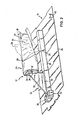
- the filleting apparatus shown in Figure 1 comprises a frame 1 with four legs 2-5, two longitudinal girders 6 and 7 and three cross bars 8-10. Arms 11 on the legs 2/3 and 4/5 support the shafts 12 and 13 for sprockets 14 and 15 of a tabletop chain 16.
- the shaft 13 can be driven by a (not represented) electromotor or hydromotor and is also provided with known (not represented) means to bring and keep the tabletop chain under the right tension.
- Retaining means 17 are provided on the table- tbp chain 16 at regular distances e.g. at a length of six links of the tabletop chain, said retaining means further elucidated by Figures 2 and 10-12.
- an angular strip 18, 19 is provided to guide the tabletop chain and/or prevent the links of the tabletop chain from tilting about a horizontal axis.
- a gate member 21 is mounted on the frame 1, which will be further elucidated from Figures 3 and 4. Said gate member is connected with the frame by means of triangular plates 22.
- Figure 2 gives details of a first embodiment of the retaining means 17 comprising a moulding piece 23 which is connected to a link 25 of the tabletop chain 16 by means of a support member 24.
- the moulding piece 23 has a smoothly progressing cross-sectional diameter which is adapted to the interior of the poultry carcass and preferably is made from plastic. At about half its length an obliquely downwardly running breast 26 is provided having a thickness which is approximately equal to the thickness of the carcass. More to the front the moulding piece is tapered to two recesses 27 for receiving the wing joint bones 30 of the poultry. Some important parts of the poultry are indicated in dotted lines: a keel bone 28, a number of ribs 29 and both wing joint bones 30.
- the support member 24 ( Figure 2) comprises a support plate 31 being placed transversely to the direction of motion of the tabletop chain and having holes for passing through securing screws 32 which can be screwed in the moulding piece 23.
- the support plate 31 is connected by a vertical triangular plate 33 to a girder 34 having a length of about five links 25.
- the girder is welded onto the link which is nearest to the support plate 31.
- the various welds are indicated by reference numerals 35 in the drawing.
- the front and rear parts of the girders 34 come free from the surface of the links 25 adjacent to the "central" link.
- the rear parts of the girders 34 fit into cups 36 having a U-like shape in upper view, which are mounted e.g. by welds 35 on the respective links. Said cups 36 promote the centering of the retaining means 17 and provide a better load distribution at the moment of pushing off the fillets by the gate member 21.
- moulding piece 23 and the support member 24 are removably interconnected it is, in general, hardly ever necessary to adapt the moulding pieces 23 to the dimensions of the poultry since the dimensions of the carcasses thereof appear to deviate from one another much less than would be assumed in first instance.
- FIGS 3 and 4 are details of the gate member 21 comprising a porch 37 which is reinforced by triangular plates 22.
- a slotted plate 39 is fastened to a cross plate 38. This fastening can be released by screw joints 40, so that the dimensions of the free passage opening 41 of the slotted plate can be eventually adapted to the kind of poultry to be operated, one and another in the same way as could be done with the moulding pieces 23.
- two lateral pushing means 42 can be seen at either side of the passage opening 41, which are mounted to the end of a piston rod 43 which can be reciprocated in a cylinder 44.
- the centerlines of the cylinders 44 are directed obliquely downwardly to one another in such a way that the lateral pushing means 42 push the wing joint bones 30 ( Figure 2) to one another just before the poultry enters the passage opening 41.
- the pushing means 42 are controlled by vertically directed cams 45 (Figure 2) which are provided on every sixth link 25 along one of the outer edges thereof and which contact during operation a feeler 46 provided on the longitudinal girder 7 ( Figure 1).
- valves are operated then which alternatingly supply compressed fluidum, such as air to the hoses 48 and 49 to reciprocate the piston rods 43.
- the filleting apparatus represented in Figure 5 also comprises a frame 1 with four legs 2-5, two longitudinal girders 6 and 7 and three cross bars 8-10.
- Arms 11 on the legs 2/3 and 4/5 support the shafts 12 and 13 for sprockets 14 and 15 of a tabletop chain 16.
- the shaft 13 can be driven by a (not represented) electromotor or hydromotor and is also provided with known (not represented) means to bring and keep the tabletop chain under the right tension.
- Retaining means 17 are provided on the tabletop chain 16 at regular distances e.g. at a length of a six links of the tabletop chain, said retaining means being further elucidated from Figures 10-12.
- an angular strip 18, 19 is provided to guide the links and/orto preventthe links of the tabletop chain from tilting about a horizontal axis.
- a pre-porch 52 In the direction of movement of the upper run of the tabletop chain, i.e. in Figures 5, 6 and 10 from the left to the right, on the frame 1 are mounted successively: a pre-porch 52, and a gate member 21.
- the pre-porch and the gate member which is very important for the present invention, will be elucidated more in detail from Figures 6-8.
- the front and rear parts of the girders 34 come free from the surface of the links 25 adjacent to the "central" link.
- the rear parts of the girders 34 can fit, just like in Figure 1, into cups having a U-like shape in upper view, which are mounted on the respective links. Said cups promote the centering of .the retaining means 17 and provide a more favourable distribution of load at the moment of pushing off the fillets into the gate member 21.
- pre-porch 52 becomes effective, which is arranged just in front of the gate member 21 which has to push off the fillets from the carcass.
- the pre-porch 52 which can be seen more in detail in Figure 6, supports two slides 59, which diverge downwardly with respect to one another, of which slides the rearwardly directed end, which engages the carcasses first, is bent slightly upwardly.
- two rods 60 are welded which connect the slide rotatably about shafts 61, 62 with the pivotal ends of two pivot plates 63, which on their turn are connected rotatably about their shafts 64 and 65 with the pre-porch 52 and a horizontal arm 66 thereof, respectively.
- the system of pivot plates 63 and shafts 61/62 and 64/65 is designed in such a way that there is question of a parallelogram hinge, the slides 59 of which always remain parallel to themselves.
- a draw-spring 67 By connecting the shafts 62 and 64 by a draw-spring 67, the slides 69 are under a sufficient downward tension to bring incorrectly placed carcasses, if any, in the right position.
- the pre-porch 52 can also be embodied as a device to cut the fillets into halves.
- the gate member 21 of the embodiment of Figues 5-8 is embodied very differently from the embodiment of Figures 1, 3 and 4. I . n the way represented in Figures 5 and 6 the gate member 21 comprises a porch 37 which is welded to the frame 1.
- the porch 37 supports a cross plate 38 which, seen in the direction of movement of the conveyor is at a rearward angle a, said angle a preferably being 23°.
- the cross plate 38 at its lower part is connected with the porch 37 by a shaft 68 and at its upper part by a screw joint 69, so that it may be suggested that there is question of an adjustable angle a. As will be explained herebelow this is, however, not the case and the represented embodiment has to be considered as a prototype embodiment.
- the cross plate 38 has a passage opening 41, the circumference of which is determined by the circumference of the carcasses to be operated.
- two lateral pushing means 42 can be seen, which are mounted to the end of a piston rod 43 which can be reciprocated in a cylinder 44.
- the centerlines of the cylinders 44 are directed to one another so that the lateral pushing means 42 press the wing joint bones to one another just before the carcass enters the passage opening 41.
- a central pushing means 70 is provided now onto the end of a piston rod 71 which can be reciprocated in a cylinder 72. Details of the central pushing means will be elucidated from Figure 8. It is mentioned here already, that the central pushing means serves to roll off the upper muscle of the keel bone from the carcass. Since this muscle lies somewhat rearwardly with respect to the wing joint bones, it is a characterizing feature of the operation of the apparatus that all three pushing means 42 and 70 are moved almost simultaneously to the operative position by (not represented) control means, indeed, but that the lateral pushing means 42 are returned obviously sooner than the central pushing means 70.
- the central pushing means 70 has a rear wall 73 which in mounted position of the central pushing means is parallel to the cross plate 38 of the gate member 21.
- Two narrow side walls 74 are arranged perpendicularly to said rear wall, said walls merging into converging wall parts 75 which merge into two protrusions 76 extending in longitudinal direction of the apparatus.
- These protrusions 76 have a lower surface 77 ( Figure 6) which is parallel to the surface of the tabletop chain 16, and a pointed front part 78 ( Figure 8) which is adapted to engage the carcass precisely below the upper muscle of the keel bone.
- the feature that the lower surface 77 is parallel to the surface of the tabletop chain 16. means that the lower surface 77 should also be at an angle a with respect to the rear wall 73 of the central pushing means. This is the very reason why the earlier described angle a is not an adjustable angle.
- a retaining means 17 When a retaining means 17 is moved through the gate member 21, the fillets are properly pushed off or rolled onto and along the triangular plate 33 of the retaining means 17 and can be put in a box by a person in the agreed way.
- the retaining means 17 is returned through the lower run of the conveyor to the place at the left side of Figure 5 in order to be re-loaded with a carcass.
- a device 55 has been mounted to remove the carcasses from the retaining means.
- This device comprises a shaft 56 which supports a drum 57 having around its periphery a number of rubber flaps 58.
- the number of revolutions of the shaft 56 preferably is such that the rotational velocity at the extremities of the flaps 58 is slightly greater than the velocity of the retaining means 17.
- control valves for the driving -of the tabletop chain 16, the pushing means 42 and 70, and the device 55 for removing the carcasses are housed in a casing 79 on top of the gate member 21.
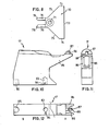
- the retaining means 17 shown in Figures 10-12 is designed to'be directly connected to a link of the tabletop chain 16 of an apparatus as shown in either Figure 1 or 5 or 9.
- the lower surface ( Figure 12B) is provided with two apertures: a bigger aperture 83 to accommodate a (not shown) bushing having internal screw thread so that the retaining means can be connected to a link which is provided with a hole at the correct position, and a smaller aperture 84 to accommodate a (not shown) pin extending from the link to avoid rotation of the retaining means around an axis perpendicular to the link when they move around.the sprockets.
- the upper part of the retaining means shown in Figures 10-12 is adapted to the interior of the poultry carcass and has a somewhat anvil-like shape, be it that the forwardly directed protrusions 36 in fact consists of two parallel triangular mould parts (see Figure 12A).
- An upright cam 87 having a slanting front surface 88 extends between both triangular mould parts and is adapted to receive the wing joint bones 30 ( Figure 2) if they are pushed to one another by the lateral pushing means 42 ( Figures 3 and 7).
Landscapes
- Life Sciences & Earth Sciences (AREA)
- Engineering & Computer Science (AREA)
- Wood Science & Technology (AREA)
- Zoology (AREA)
- Food Science & Technology (AREA)
- Processing Of Meat And Fish (AREA)
- Paper (AREA)
- Meat, Egg Or Seafood Products (AREA)
Claims (8)
Priority Applications (1)
| Application Number | Priority Date | Filing Date | Title |
|---|---|---|---|
| AT84201055T ATE30202T1 (de) | 1983-07-13 | 1984-07-13 | Vorrichtung zum filetieren. |
Applications Claiming Priority (2)
| Application Number | Priority Date | Filing Date | Title |
|---|---|---|---|
| NL8302494A NL8302494A (nl) | 1983-07-13 | 1983-07-13 | Fileermachine. |
| NL8302494 | 1983-07-13 |
Publications (2)
| Publication Number | Publication Date |
|---|---|
| EP0132890A1 EP0132890A1 (de) | 1985-02-13 |
| EP0132890B1 true EP0132890B1 (de) | 1987-10-14 |
Family
ID=19842152
Family Applications (1)
| Application Number | Title | Priority Date | Filing Date |
|---|---|---|---|
| EP84201055A Expired EP0132890B1 (de) | 1983-07-13 | 1984-07-13 | Vorrichtung zum Filetieren |
Country Status (6)
| Country | Link |
|---|---|
| US (1) | US4593432A (de) |
| EP (1) | EP0132890B1 (de) |
| AT (1) | ATE30202T1 (de) |
| CA (1) | CA1225803A (de) |
| DE (1) | DE3466751D1 (de) |
| NL (1) | NL8302494A (de) |
Cited By (1)
| Publication number | Priority date | Publication date | Assignee | Title |
|---|---|---|---|---|
| CN103355396A (zh) * | 2012-02-03 | 2013-10-23 | 北欧机械制造鲁道夫巴德尔有限及两合公司 | 对屠宰动物体的毛皮刻痕的装置、动物体支撑体、使用该装置的处理装置及毛皮刻痕方法 |
Families Citing this family (32)
| Publication number | Priority date | Publication date | Assignee | Title |
|---|---|---|---|---|
| US4682386A (en) * | 1983-07-13 | 1987-07-28 | Systemate B.V. | Poultry breast filleting system |
| NL8501748A (nl) * | 1985-06-18 | 1987-01-16 | Systemate Bv | Fileermachine. |
| NL8503287A (nl) * | 1985-11-27 | 1987-06-16 | Stork Pmt | Werkwijze en inrichting voor het ondersteunen van een karkas of karkasdeel van geslacht gevogelte. |
| US4704769A (en) * | 1986-04-25 | 1987-11-10 | Hanechak Edward S | Fish filleting apparatus and method |
| US4827570A (en) * | 1988-01-25 | 1989-05-09 | Simon-Johnson, Inc. | Method and apparatus for removing breast meat from poultry carcass |
| US5045022A (en) * | 1990-01-31 | 1991-09-03 | Hazenbroek Jacobus E | Adjustable poultry breast filleting system |
| NL9401773A (nl) † | 1994-10-26 | 1996-06-03 | Meyn Maschf | Werkwijze en inrichting voor het fileren van een borststuk van geslacht gevogelte. |
| US5569068A (en) * | 1995-06-02 | 1996-10-29 | The Laitram Corporation | Method and apparatus for skinning fish |
| NL1005107C2 (nl) * | 1997-01-28 | 1998-07-29 | Meyn Maschf | Inrichting voor het fileren van een van een geslachte vogel afkomstig borstgedeelte. |
| US5951393A (en) * | 1998-03-17 | 1999-09-14 | Systemate Holland, B.V. | Poultry breast filleting mandrel |
| US6042468A (en) * | 1998-08-20 | 2000-03-28 | Lucero; Kevin | Chicken breast deboning stabilization device |
| US6283847B1 (en) * | 2000-02-10 | 2001-09-04 | Allan Todd Berry | Poultry breast cartilage harvesting system |
| DK2258202T3 (en) † | 2002-12-20 | 2015-03-02 | Marel Stork Poultry Proc Bv | Method and device for working a body part of slaughtered poultry |
| NL1027426C2 (nl) * | 2004-11-05 | 2006-05-15 | Systemate Group Bv | Fileermachine voor gevogelte. |
| US8591298B1 (en) * | 2008-02-21 | 2013-11-26 | Three Dick Farms, Inc. | Poultry wing deboning apparatus and method |
| US8632380B2 (en) | 2010-01-26 | 2014-01-21 | Foodmate B.V. | Method and apparatus for removing a sleeve of meat from an animal part having bone with knuckles on each of its opposite ends |
| US8157625B2 (en) | 2010-01-26 | 2012-04-17 | Foodmate Bv | Method and apparatus for collecting meat from an animal part |
| US8757354B2 (en) | 2010-04-19 | 2014-06-24 | Foodmate Bv | Turning block alignment |
| NL2006075C2 (en) | 2011-01-26 | 2012-07-30 | Foodmate B V | Rotationally indexed article support for a conveyor system having an alignment station. |
| US8789684B2 (en) | 2010-04-19 | 2014-07-29 | Foodmate Bv | Rotatable article support for a conveyor |
| NL2004573C2 (en) | 2010-04-19 | 2011-10-20 | Foodmate B V | Turning block alignment. |
| NL2004574C2 (en) | 2010-04-19 | 2011-10-20 | Foodmate B V | Rotatable article support for a conveyor. |
| US8727839B2 (en) | 2011-01-21 | 2014-05-20 | Foodmate Bv | Poultry wing cutter for narrow pitch poultry lines |
| US8267241B2 (en) | 2011-01-26 | 2012-09-18 | Foodmate Bv | Rotationally indexed article support for a conveyor system having an alignment station |
| US8882571B2 (en) | 2011-01-26 | 2014-11-11 | Foodmate Bv | Method of deboning animal thighs for separating and collecting meat therefrom and apparatus for performing the method |
| WO2012102609A1 (en) | 2011-01-26 | 2012-08-02 | Foodmate B.V. | Method of deboning animal thighs for separating and collecting meat there from and apparatus for performing the method |
| US8430728B2 (en) | 2011-02-14 | 2013-04-30 | Foodmate Bv | Special cut poultry wing cutter |
| NL2009033C2 (en) | 2012-06-19 | 2013-12-23 | Foodmate B V | Weighing method and apparatus. |
| NL2009718C2 (en) | 2012-10-29 | 2014-05-01 | Foodmate B V | Method of mechanically removing skin from animal parts. |
| US8808068B2 (en) | 2012-10-29 | 2014-08-19 | Foodmate Bv | Method of and system for automatically removing meat from an animal extremity |
| US9078453B2 (en) | 2013-11-01 | 2015-07-14 | Foodmate B.V. | Method and system for automatically deboning poultry breast caps containing meat and a skeletal structure to obtain breast fillets therefrom |
| US8961274B1 (en) | 2013-12-18 | 2015-02-24 | Foodmate Bv | Selective tendon cutter and method |
Family Cites Families (17)
| Publication number | Priority date | Publication date | Assignee | Title |
|---|---|---|---|---|
| US1639976A (en) * | 1927-03-22 | 1927-08-23 | Barry James | Fish-cutting machine |
| US2897536A (en) * | 1958-04-04 | 1959-08-04 | Campbell Soup Co | Poultry boning machine |
| US3296653A (en) * | 1963-09-03 | 1967-01-10 | Asa B Segur | Apparatus for use in removing meat from poultry wings |
| US3531825A (en) * | 1967-06-14 | 1970-10-06 | Asa B Segur | Apparatus for de-boning raw poultry meat |
| US3629903A (en) * | 1969-08-08 | 1971-12-28 | Nadine Turner | Device for and method of preparing fowl wings |
| US3665553A (en) * | 1970-04-07 | 1972-05-30 | Avi Simplot Inc | Keel bone extractor for poultry products |
| US3672000A (en) * | 1970-08-31 | 1972-06-27 | Victor F Weaver Inc | Machine to de-bone chicken thighs |
| DE2110080A1 (en) * | 1971-03-03 | 1972-09-21 | Poultry filleter - with hand operated knife contoured to shape of poultry breast | |
| GB1513243A (en) * | 1974-05-14 | 1978-06-07 | Unilever Ltd | Method and apparatus for filleting fish |
| US3982299A (en) * | 1975-05-01 | 1976-09-28 | Burns Foods Limited | Meat cutter |
| US4216565A (en) * | 1979-02-26 | 1980-08-12 | Anthony J. Volk | Meat stripping machine for fowl |
| US4327463A (en) * | 1980-10-10 | 1982-05-04 | Victor F. Weaver, Inc. | Single station anatomical section de-boning machine |
| US4402112A (en) * | 1981-04-02 | 1983-09-06 | Gasbarro Geno N | Automatic poultry deboning apparatus |
| US4359807A (en) * | 1981-04-28 | 1982-11-23 | Oscar Mayer Foods Corporation | Meat gristle puller |
| US4377884A (en) * | 1981-07-29 | 1983-03-29 | Viscolosi Louis A | Apparatus for deboning poultry legs |
| US4385419A (en) * | 1982-03-15 | 1983-05-31 | Cantrell Machine Co., Inc. | Chicken deboning apparatus and method |
| US4424608A (en) * | 1982-04-01 | 1984-01-10 | Victor F. Weaver, Inc. | Automatic poultry breast processing machine and method |
-
1983
- 1983-07-13 NL NL8302494A patent/NL8302494A/nl not_active Application Discontinuation
-
1984
- 1984-07-13 EP EP84201055A patent/EP0132890B1/de not_active Expired
- 1984-07-13 US US06/630,658 patent/US4593432A/en not_active Expired - Lifetime
- 1984-07-13 DE DE8484201055T patent/DE3466751D1/de not_active Expired
- 1984-07-13 AT AT84201055T patent/ATE30202T1/de not_active IP Right Cessation
- 1984-07-13 CA CA000458816A patent/CA1225803A/en not_active Expired
Cited By (2)
| Publication number | Priority date | Publication date | Assignee | Title |
|---|---|---|---|---|
| CN103355396A (zh) * | 2012-02-03 | 2013-10-23 | 北欧机械制造鲁道夫巴德尔有限及两合公司 | 对屠宰动物体的毛皮刻痕的装置、动物体支撑体、使用该装置的处理装置及毛皮刻痕方法 |
| CN103355396B (zh) * | 2012-02-03 | 2016-01-20 | 北欧机械制造鲁道夫巴德尔有限及两合公司 | 对屠宰动物体的毛皮刻痕的装置、动物体支撑体、使用该装置的处理装置及毛皮刻痕方法 |
Also Published As
| Publication number | Publication date |
|---|---|
| ATE30202T1 (de) | 1987-10-15 |
| US4593432A (en) | 1986-06-10 |
| CA1225803A (en) | 1987-08-25 |
| DE3466751D1 (en) | 1987-11-19 |
| EP0132890A1 (de) | 1985-02-13 |
| NL8302494A (nl) | 1985-02-01 |
Similar Documents
| Publication | Publication Date | Title |
|---|---|---|
| US4593432A (en) | Filleting apparatus | |
| US3979793A (en) | Poultry eviscerating apparatus | |
| EP1769681B1 (de) | Verfahren und Vorrichtung zur Bearbeitung des Organpakets eines Schlachttieres | |
| US5147240A (en) | Thigh joint separator and carcass halving apparatus | |
| EP0054060B1 (de) | Geflügelschneidevorrichtung | |
| US5080630A (en) | Poultry processing apparatus and method | |
| US4424608A (en) | Automatic poultry breast processing machine and method | |
| US4682386A (en) | Poultry breast filleting system | |
| US4558490A (en) | Poultry cut up machine | |
| EP0440032B1 (de) | Einstellbares System zum Filettieren von Geflügelbrust | |
| US8535123B2 (en) | Deboner | |
| US4385421A (en) | Poultry leg/back processor | |
| EP0381093A1 (de) | Verstellbare Vorrichtung zur Zerteilung des Gerippes von Geflügel | |
| EP0145077A2 (de) | Vorrichtung zum Transportieren von Geflügel zu einem Schlachthaus | |
| US4477942A (en) | Poultry breast de-boning machine and processing method | |
| NL9101768A (nl) | Inrichting voor het verwijderen van de ingewanden uit de buikholte van gevogelte. | |
| US4251901A (en) | Apparatus and method for splitting poultry breasts | |
| US6450873B2 (en) | Method and device for processing poultry | |
| WO1993009675A1 (en) | Dark meat deboner with leg scraper | |
| JP7018454B2 (ja) | 骨付き肉の筋入れ装置及び骨付き肉の筋入れ方法 | |
| US3663991A (en) | Method and apparatus for eviscerating chickens or other fowl | |
| US4610051A (en) | Turkey thigh skinner | |
| CA1046714A (en) | Apparatus for removing the neck from a fowl | |
| US5569069A (en) | Apparatus for cutting wings from poultry | |
| US4557015A (en) | Poultry halving machine |
Legal Events
| Date | Code | Title | Description |
|---|---|---|---|
| PUAI | Public reference made under article 153(3) epc to a published international application that has entered the european phase |
Free format text: ORIGINAL CODE: 0009012 |
|
| AK | Designated contracting states |
Designated state(s): AT BE CH DE FR GB IT LI LU NL SE |
|
| 17P | Request for examination filed |
Effective date: 19850806 |
|
| 17Q | First examination report despatched |
Effective date: 19860604 |
|
| GRAA | (expected) grant |
Free format text: ORIGINAL CODE: 0009210 |
|
| AK | Designated contracting states |
Kind code of ref document: B1 Designated state(s): AT BE CH DE FR GB IT LI LU NL SE |
|
| REF | Corresponds to: |
Ref document number: 30202 Country of ref document: AT Date of ref document: 19871015 Kind code of ref document: T |
|
| ITF | It: translation for a ep patent filed | ||
| ET | Fr: translation filed | ||
| REF | Corresponds to: |
Ref document number: 3466751 Country of ref document: DE Date of ref document: 19871119 |
|
| PLBI | Opposition filed |
Free format text: ORIGINAL CODE: 0009260 |
|
| 26 | Opposition filed |
Opponent name: STORK PMT B.V. Effective date: 19880711 |
|
| NLR1 | Nl: opposition has been filed with the epo |
Opponent name: STORK PMT B.V. |
|
| PLBN | Opposition rejected |
Free format text: ORIGINAL CODE: 0009273 |
|
| STAA | Information on the status of an ep patent application or granted ep patent |
Free format text: STATUS: OPPOSITION REJECTED |
|
| 27O | Opposition rejected |
Effective date: 19900224 |
|
| NLR2 | Nl: decision of opposition | ||
| ITTA | It: last paid annual fee | ||
| EPTA | Lu: last paid annual fee | ||
| EAL | Se: european patent in force in sweden |
Ref document number: 84201055.5 |
|
| PGFP | Annual fee paid to national office [announced via postgrant information from national office to epo] |
Ref country code: LU Payment date: 19950701 Year of fee payment: 12 |
|
| PGFP | Annual fee paid to national office [announced via postgrant information from national office to epo] |
Ref country code: GB Payment date: 19960704 Year of fee payment: 13 |
|
| PG25 | Lapsed in a contracting state [announced via postgrant information from national office to epo] |
Ref country code: LU Free format text: LAPSE BECAUSE OF NON-PAYMENT OF DUE FEES Effective date: 19960713 |
|
| PGFP | Annual fee paid to national office [announced via postgrant information from national office to epo] |
Ref country code: SE Payment date: 19960719 Year of fee payment: 13 Ref country code: AT Payment date: 19960719 Year of fee payment: 13 |
|
| PGFP | Annual fee paid to national office [announced via postgrant information from national office to epo] |
Ref country code: FR Payment date: 19960724 Year of fee payment: 13 |
|
| PGFP | Annual fee paid to national office [announced via postgrant information from national office to epo] |
Ref country code: NL Payment date: 19960731 Year of fee payment: 13 Ref country code: CH Payment date: 19960731 Year of fee payment: 13 |
|
| PGFP | Annual fee paid to national office [announced via postgrant information from national office to epo] |
Ref country code: BE Payment date: 19960802 Year of fee payment: 13 |
|
| PGFP | Annual fee paid to national office [announced via postgrant information from national office to epo] |
Ref country code: DE Payment date: 19960806 Year of fee payment: 13 |
|
| PG25 | Lapsed in a contracting state [announced via postgrant information from national office to epo] |
Ref country code: GB Free format text: LAPSE BECAUSE OF NON-PAYMENT OF DUE FEES Effective date: 19970713 Ref country code: AT Free format text: LAPSE BECAUSE OF NON-PAYMENT OF DUE FEES Effective date: 19970713 |
|
| PG25 | Lapsed in a contracting state [announced via postgrant information from national office to epo] |
Ref country code: SE Effective date: 19970714 |
|
| PG25 | Lapsed in a contracting state [announced via postgrant information from national office to epo] |
Ref country code: LI Free format text: LAPSE BECAUSE OF NON-PAYMENT OF DUE FEES Effective date: 19970731 Ref country code: CH Free format text: LAPSE BECAUSE OF NON-PAYMENT OF DUE FEES Effective date: 19970731 Ref country code: BE Free format text: LAPSE BECAUSE OF NON-PAYMENT OF DUE FEES Effective date: 19970731 |
|
| BERE | Be: lapsed |
Owner name: SYSTEMATE HOLLAND B.V. Effective date: 19970731 |
|
| PG25 | Lapsed in a contracting state [announced via postgrant information from national office to epo] |
Ref country code: NL Free format text: LAPSE BECAUSE OF NON-PAYMENT OF DUE FEES Effective date: 19980201 |
|
| GBPC | Gb: european patent ceased through non-payment of renewal fee |
Effective date: 19970713 |
|
| REG | Reference to a national code |
Ref country code: CH Ref legal event code: PL |
|
| PG25 | Lapsed in a contracting state [announced via postgrant information from national office to epo] |
Ref country code: FR Free format text: LAPSE BECAUSE OF NON-PAYMENT OF DUE FEES Effective date: 19980331 |
|
| NLV4 | Nl: lapsed or anulled due to non-payment of the annual fee |
Effective date: 19980201 |
|
| PG25 | Lapsed in a contracting state [announced via postgrant information from national office to epo] |
Ref country code: DE Free format text: LAPSE BECAUSE OF NON-PAYMENT OF DUE FEES Effective date: 19980401 |
|
| EUG | Se: european patent has lapsed |
Ref document number: 84201055.5 |
|
| REG | Reference to a national code |
Ref country code: FR Ref legal event code: ST |