EP0132947A1 - Procédé d'inspection de profil commandé par un programme d'ordinateur - Google Patents
Procédé d'inspection de profil commandé par un programme d'ordinateur Download PDFInfo
- Publication number
- EP0132947A1 EP0132947A1 EP84304312A EP84304312A EP0132947A1 EP 0132947 A1 EP0132947 A1 EP 0132947A1 EP 84304312 A EP84304312 A EP 84304312A EP 84304312 A EP84304312 A EP 84304312A EP 0132947 A1 EP0132947 A1 EP 0132947A1
- Authority
- EP
- European Patent Office
- Prior art keywords
- workpiece
- stylus
- process according
- configurations
- inspected
- Prior art date
- Legal status (The legal status is an assumption and is not a legal conclusion. Google has not performed a legal analysis and makes no representation as to the accuracy of the status listed.)
- Withdrawn
Links
Images


Classifications
-
- G—PHYSICS
- G01—MEASURING; TESTING
- G01B—MEASURING LENGTH, THICKNESS OR SIMILAR LINEAR DIMENSIONS; MEASURING ANGLES; MEASURING AREAS; MEASURING IRREGULARITIES OF SURFACES OR CONTOURS
- G01B7/00—Measuring arrangements characterised by the use of electric or magnetic techniques
- G01B7/004—Measuring arrangements characterised by the use of electric or magnetic techniques for measuring coordinates of points
- G01B7/008—Measuring arrangements characterised by the use of electric or magnetic techniques for measuring coordinates of points using coordinate measuring machines
-
- G—PHYSICS
- G05—CONTROLLING; REGULATING
- G05B—CONTROL OR REGULATING SYSTEMS IN GENERAL; FUNCTIONAL ELEMENTS OF SUCH SYSTEMS; MONITORING OR TESTING ARRANGEMENTS FOR SUCH SYSTEMS OR ELEMENTS
- G05B19/00—Program-control systems
- G05B19/02—Program-control systems electric
- G05B19/18—Numerical control [NC], i.e. automatically operating machines, in particular machine tools, e.g. in a manufacturing environment, so as to execute positioning, movement or co-ordinated operations by means of program data in numerical form
- G05B19/19—Numerical control [NC], i.e. automatically operating machines, in particular machine tools, e.g. in a manufacturing environment, so as to execute positioning, movement or co-ordinated operations by means of program data in numerical form characterised by positioning or contouring control systems, e.g. to control position from one programmed point to another or to control movement along a programmed continuous path
- G05B19/21—Numerical control [NC], i.e. automatically operating machines, in particular machine tools, e.g. in a manufacturing environment, so as to execute positioning, movement or co-ordinated operations by means of program data in numerical form characterised by positioning or contouring control systems, e.g. to control position from one programmed point to another or to control movement along a programmed continuous path using an incremental digital measuring device
- G05B19/25—Numerical control [NC], i.e. automatically operating machines, in particular machine tools, e.g. in a manufacturing environment, so as to execute positioning, movement or co-ordinated operations by means of program data in numerical form characterised by positioning or contouring control systems, e.g. to control position from one programmed point to another or to control movement along a programmed continuous path using an incremental digital measuring device for continuous-path control
-
- G—PHYSICS
- G05—CONTROLLING; REGULATING
- G05B—CONTROL OR REGULATING SYSTEMS IN GENERAL; FUNCTIONAL ELEMENTS OF SUCH SYSTEMS; MONITORING OR TESTING ARRANGEMENTS FOR SUCH SYSTEMS OR ELEMENTS
- G05B2219/00—Program-control systems
- G05B2219/30—Nc systems
- G05B2219/37—Measurements
- G05B2219/37206—Inspection of surface
Definitions
- This invention relates generally to an inspection process for measuring selected dimensions of a workpiece, more particularly for, determining the locations and and shapes of scorelines and edges of flat paperboard carton blanks in order to assess the accuracy thereof to such a method wherein a stylus or probe is computer programme-controlled to move rapidly across panels in between scorelines and openings, and then slowly over such scorelines or the edges of openings, producing a voltage signal which is proportional to its vertical displacement.
- On object of the invention is to enable computer programme-controlled inspection of the locations and shapes of cut edges and scorelines of selected surfaces, such as flat paperboard carton blanks, and comparing same with desired manufacturing tolerances.
- Another object of the invention is to provide such a computer programme-controlled carton blank inspection means, wherein a vertically oriented electromechanical transducer- type stylus or probe is mounted on a stepping motor-driven slide member along one axis, with the latter slide member, in turn, being mounted on a second stepping motor-driven slide member for movement along another axis, for traversing selected areas of the blank.
- a further object of the invention is to provide such a computer programme-controlled carton blank inspection means and, additionally a printer for printing linear distances between scorelines on a layout thereof, and a cathode ray tube screen for displaying the cross-sectional shape of any scoreline being inspected.
- Still another object of the invention is to provide a computer programme-controlled carton blank inspection means wherein those linear distances between scorelines which are compared with and found to be outside of manufacturing tolerances are printed on a layout of the carton blank.
- the apparatus (10) shown in Figures 1 to 3, includes a stationary inspection table 12 having a pair of oppositely disposed slide members 14 mounted on oppositely disposed edges of the table 12 for slidable movement along the X-axis.
- a support bar 16 straddles the pair of slide members and a further slide member 18 mounted on the support bar for slidable movement along the Y-axis.
- Stepping motors 20 and 22 mounted on the inspection table 12 are operatively connected to the slide members 14 and 18, respectively.
- suitable computer means 32 including microprocessors represented as 34 and 36; a keyboard 38; a printer 40; and a cathode ray tube screen or other visual display unit 42.
- the processor 34 is adapted to receive input discs 44 with any suitable programme incorporated thereon for inspecting a selected paperboard carton blank 46 placed in a particular location on the inspection table 12 beneath the inspection stylus 30.
- the transducer 24 generates a voltage signal proportional to the vertical displacement of its stylus 30 which is connected via an amplified analog signal to a digital signal, and communicating the latter to the micro processor 36.
- Each stepping motor 20 and 22 has an encoder 52 and 54, respectively, coupled thereto for providing a feedback signal to the micro processor 36. The feedback signal is continuously compared with command signals sent to the stepping motors.
- Limit switches 56, 58, 60 and 62 are mounted on the inspection table 12 to limit the X and Y axis movements in both directions for each.
- a selected workpiece such as a paperboard carton blank 46 which for example, may be for pint, pint, quart, half gallon, or other similar sized folding cartons
- a selected workpiece such as a paperboard carton blank 46 which for example, may be for pint, pint, quart, half gallon, or other similar sized folding cartons
- the disk 44 bearing a desired program is loaded into the computer means 32.
- the program causes either the table 12 and the blank 46 mounted thereon to move in predetermined directions beneath a fixed stylus 30, or the stylus 30 to move relative to a fixed table 12 and an associated blank 46, depending upon the table 12 and stylus 30 designs selected.
- the stylus 30 and the associated slide member 18 are caused to move in a Y direction along the support bar 16, while the slide member 18 is caused to move in an X direction along the slide members 14.
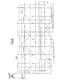
- the relative movement between the stylus 30 and the blank 46 is programmed to start at a "home position" of selected zero X and Y coordinates ( Figure 3), along a path or route such as that illustrated in Figure 3, which is predetermined by the data stored in the path table.
- This data consists of (1) a series of X and Y coordinate positions toward and away from which the relative movement occurs, and (2) changes of speed rates from high speed to low speed between inspection points wherein elevational data is collected, resulting from the vertical displacement of the core 26 of the stylus 30, amplification by the amplifier 48, conversion to a digital signal by the converter 50, and communication to the computer meana 32.
- inspection points may involve score lines and edges, for example, but are also applicable to the edges of separate layers attached to the upper surface of the workpiece.
- the stylus 30 moves away from the zero coordinate location at the start of a test, it is caused to pass over a gauge block, represented as 51, which duplicates a known score line height.
- the resultant output signal is thereupon calibrated by the software program to this known,gauge block height.
- the encoders 52 and 54 serve to count stepping motor 20 and 22 pulses from the zero position.
- the motors may be such that there are 200 pulses or steps per revolution.
- the table 12 leadscrew is selected to have a pitch of .200 inches per revolution, then each pulse or step of the motor indexes the table along its axis by .001 , inch.
- the computer thereafter knows the position of the stylus relative to the starting point, and is programmed to collect height data intermediate selected points .200 inches on each side of an assumed centre of each score line to be checked, or on each side of a cut edge.
- the stylus 30 sends height data to the computer for each of the 400 intermediate steps.
- the computer is thus able to compute the highest point or centre of the score line as a reference for printing the linear distance between score lines on the printer 40, and to compute the cross-sectional shape of the score line for projection on the screen 42.
- the software is structured such that, at the beginning of each data collection series on a new blank 46, the transducer 24 is "zeroed out” with respect to the thickness of the selected blank relative to the plane of the table 12. Thereafter, during the collection process, the actual lateral and height dimensions are measured as indicated above, and compared to the nominal or blueprint values which are stored in the appropriate data storage tables.
- the print-out arrangement may be such that it is only if the variance exceeds the manufacturing tolerance for any particular dimension that the dimension will be printed, or, if desired, each measured dimension may be printed. In any event, the shape of each score line at the cross-over points may be shown on the screen 42, as well as printed by the printer 40, at the operator's discretion.
Landscapes
- Engineering & Computer Science (AREA)
- Physics & Mathematics (AREA)
- General Physics & Mathematics (AREA)
- Human Computer Interaction (AREA)
- Manufacturing & Machinery (AREA)
- Automation & Control Theory (AREA)
- Length Measuring Devices With Unspecified Measuring Means (AREA)
- Measurement Of Length, Angles, Or The Like Using Electric Or Magnetic Means (AREA)
- Length-Measuring Instruments Using Mechanical Means (AREA)
Applications Claiming Priority (2)
| Application Number | Priority Date | Filing Date | Title |
|---|---|---|---|
| US51754083A | 1983-07-27 | 1983-07-27 | |
| US517540 | 1983-07-27 |
Publications (1)
| Publication Number | Publication Date |
|---|---|
| EP0132947A1 true EP0132947A1 (fr) | 1985-02-13 |
Family
ID=24060223
Family Applications (1)
| Application Number | Title | Priority Date | Filing Date |
|---|---|---|---|
| EP84304312A Withdrawn EP0132947A1 (fr) | 1983-07-27 | 1984-06-26 | Procédé d'inspection de profil commandé par un programme d'ordinateur |
Country Status (9)
| Country | Link |
|---|---|
| EP (1) | EP0132947A1 (fr) |
| JP (1) | JPS6042602A (fr) |
| AU (1) | AU2950984A (fr) |
| BR (1) | BR8403729A (fr) |
| CA (1) | CA1210868A (fr) |
| DK (1) | DK365784A (fr) |
| ES (1) | ES8600531A1 (fr) |
| NO (1) | NO843012L (fr) |
| ZA (1) | ZA844705B (fr) |
Cited By (8)
| Publication number | Priority date | Publication date | Assignee | Title |
|---|---|---|---|---|
| GB2172707A (en) * | 1985-03-14 | 1986-09-24 | Mitutoyo Mfg Co Ltd | Parts inspection equipment |
| GB2202659A (en) * | 1987-02-23 | 1988-09-28 | Mitutoyo Corp | Co-ordinates measuring instrument |
| GB2212923A (en) * | 1987-11-30 | 1989-08-02 | Nat Res Dev | Methods and apparatus for measuring transverse dimensions of workpieces |
| US4918627A (en) * | 1986-08-04 | 1990-04-17 | Fmc Corporation | Computer integrated gaging system |
| GB2230364A (en) * | 1986-08-04 | 1990-10-17 | Fmc Corp | Computer-controlled display system for CAD |
| EP0342770B1 (fr) * | 1986-03-04 | 1994-05-18 | Rank Taylor Hobson Limited | Appareil métrologique |
| EP1199575A1 (fr) * | 2000-10-17 | 2002-04-24 | Sumitomo Wiring Systems, Ltd. | Dispositif de test et testeur de connecteur l'utilisant |
| EP1775544A1 (fr) * | 2005-10-11 | 2007-04-18 | Omron Europe B.V. | Table d examination |
Citations (5)
| Publication number | Priority date | Publication date | Assignee | Title |
|---|---|---|---|---|
| US3135055A (en) * | 1960-10-19 | 1964-06-02 | United Aircraft Corp | Workpiece inspection system |
| US3727119A (en) * | 1971-02-01 | 1973-04-10 | Information Dev Corp | Servo controlled automatic inspection apparatus |
| FR2341399A1 (fr) * | 1976-02-23 | 1977-09-16 | Saab Scania Ab | Procede pour controler les mesures d'une piece usinee sur une machine-outil |
| GB2049995A (en) * | 1979-05-25 | 1980-12-31 | Leitz Ernst Gmbh | Apparatus and method for measurement of a workpiece |
| EP0027186A2 (fr) * | 1979-10-11 | 1981-04-22 | Maag-Zahnräder und -Maschinen Aktiengesellschaft | Procédé pour fixer les limites de mesure dans un appareil de vérification de flancs d'engrenages et appareil de vérification de flancs d'engrenages utilisant ledit procédé |
-
1984
- 1984-06-19 AU AU29509/84A patent/AU2950984A/en not_active Abandoned
- 1984-06-21 ZA ZA844705A patent/ZA844705B/xx unknown
- 1984-06-26 EP EP84304312A patent/EP0132947A1/fr not_active Withdrawn
- 1984-07-04 CA CA000458107A patent/CA1210868A/fr not_active Expired
- 1984-07-25 JP JP59153307A patent/JPS6042602A/ja active Pending
- 1984-07-25 NO NO843012A patent/NO843012L/no unknown
- 1984-07-26 ES ES534619A patent/ES8600531A1/es not_active Expired
- 1984-07-26 BR BR8403729A patent/BR8403729A/pt unknown
- 1984-07-26 DK DK365784A patent/DK365784A/da not_active Application Discontinuation
Patent Citations (5)
| Publication number | Priority date | Publication date | Assignee | Title |
|---|---|---|---|---|
| US3135055A (en) * | 1960-10-19 | 1964-06-02 | United Aircraft Corp | Workpiece inspection system |
| US3727119A (en) * | 1971-02-01 | 1973-04-10 | Information Dev Corp | Servo controlled automatic inspection apparatus |
| FR2341399A1 (fr) * | 1976-02-23 | 1977-09-16 | Saab Scania Ab | Procede pour controler les mesures d'une piece usinee sur une machine-outil |
| GB2049995A (en) * | 1979-05-25 | 1980-12-31 | Leitz Ernst Gmbh | Apparatus and method for measurement of a workpiece |
| EP0027186A2 (fr) * | 1979-10-11 | 1981-04-22 | Maag-Zahnräder und -Maschinen Aktiengesellschaft | Procédé pour fixer les limites de mesure dans un appareil de vérification de flancs d'engrenages et appareil de vérification de flancs d'engrenages utilisant ledit procédé |
Cited By (14)
| Publication number | Priority date | Publication date | Assignee | Title |
|---|---|---|---|---|
| GB2172707A (en) * | 1985-03-14 | 1986-09-24 | Mitutoyo Mfg Co Ltd | Parts inspection equipment |
| EP0342770B1 (fr) * | 1986-03-04 | 1994-05-18 | Rank Taylor Hobson Limited | Appareil métrologique |
| GB2230364A (en) * | 1986-08-04 | 1990-10-17 | Fmc Corp | Computer-controlled display system for CAD |
| GB2230364B (en) * | 1986-08-04 | 1991-01-09 | Fmc Corp | Computer controlled display system |
| US4918627A (en) * | 1986-08-04 | 1990-04-17 | Fmc Corporation | Computer integrated gaging system |
| US4901253A (en) * | 1987-02-23 | 1990-02-13 | Mitutoyo Corporation | Coordinate measuring instrument and method of generating pattern data concerning shape of work to be measured |
| GB2202659B (en) * | 1987-02-23 | 1991-07-17 | Mitutoyo Corp | Coordinate measuring instrument and method of generating pattern data concerning shape of work to be measured |
| GB2202659A (en) * | 1987-02-23 | 1988-09-28 | Mitutoyo Corp | Co-ordinates measuring instrument |
| US4964071A (en) * | 1987-11-30 | 1990-10-16 | National Research Development Corporation | Methods and apparatus for measuring transverse dimensions of workpieces |
| GB2212923A (en) * | 1987-11-30 | 1989-08-02 | Nat Res Dev | Methods and apparatus for measuring transverse dimensions of workpieces |
| GB2212923B (en) * | 1987-11-30 | 1991-05-01 | Nat Res Dev | Measuring transverse dimensions of workpieces |
| EP1199575A1 (fr) * | 2000-10-17 | 2002-04-24 | Sumitomo Wiring Systems, Ltd. | Dispositif de test et testeur de connecteur l'utilisant |
| US6657438B2 (en) | 2000-10-17 | 2003-12-02 | Sumitomo Wiring Systems, Ltd. | Testing unit and a connector testing apparatus using the same |
| EP1775544A1 (fr) * | 2005-10-11 | 2007-04-18 | Omron Europe B.V. | Table d examination |
Also Published As
| Publication number | Publication date |
|---|---|
| ES534619A0 (es) | 1985-10-01 |
| NO843012L (no) | 1985-01-28 |
| ZA844705B (en) | 1985-02-27 |
| AU2950984A (en) | 1985-06-13 |
| DK365784D0 (da) | 1984-07-26 |
| ES8600531A1 (es) | 1985-10-01 |
| DK365784A (da) | 1985-01-28 |
| BR8403729A (pt) | 1985-07-02 |
| JPS6042602A (ja) | 1985-03-06 |
| CA1210868A (fr) | 1986-09-02 |
Similar Documents
| Publication | Publication Date | Title |
|---|---|---|
| CA1286382C (fr) | Methode et dispositif d'etalonnage d'une machine a coordonees | |
| JP2523263B2 (ja) | 据付ゲ―ジ及びその製造方法 | |
| US12226858B1 (en) | Fabrication layout device and method | |
| US4638232A (en) | Method and apparatus for calibrating a positioning system | |
| DE3714862A1 (de) | Flexible cnc-vielstellenmesseinrichtung | |
| EP1574287A2 (fr) | Appareil d'usinage | |
| EP1019669B1 (fr) | Dispositif de detection de la position de deux corps | |
| CA1210868A (fr) | Methode de controle de la configuration de pieces assistee par ordinateur | |
| DE3781674T2 (de) | Positionsbestimmungsverfahren innerhalb des messraumes eines koordinatenmessgeraetes und dergleichen und system dafuer. | |
| EP0671602A2 (fr) | Procédé et appareil pour le transfert et l'ajustement d'une relation mécaniquement correcte pour un instrument de transfert ou d'ajustement | |
| CN219319352U (zh) | 一种大尺寸三坐标测量机检定装置 | |
| CN212639422U (zh) | 板材堆垛自动调整装置 | |
| CN210513077U (zh) | 一种非金属板测厚仪误差检测校准装置 | |
| CN114636374A (zh) | 一种弦平面偏差自动测量装置及方法 | |
| US6178657B1 (en) | Apparatus and method for measuring the relative differential length in a sheet of material | |
| CN111854652A (zh) | 一种吸附板平面度检测装置及其检测方法 | |
| JP2982663B2 (ja) | 三次元測定方法及びその装置 | |
| CN113857559B (zh) | 一种板件寻边机构、切割机及板件寻边方法 | |
| JP3366052B2 (ja) | 比較測長装置 | |
| CN118424206A (zh) | 一种平面高度差的检测方法及实施该方法的设备 | |
| US20230038040A1 (en) | Fabrication workstation and layout device | |
| DE4407605A1 (de) | 3D-Koordinaten-Meßmaschine mit einem als Referenz dienenden Eichkörper | |
| JP2506231B2 (ja) | 車体の組立精度測定方法及びその装置 | |
| CN121844181A (zh) | 用于工件的定位设备 | |
| CN114935659A (zh) | 一种硅钢卷样板物理参数的自动测量装置及测量方法 |
Legal Events
| Date | Code | Title | Description |
|---|---|---|---|
| PUAI | Public reference made under article 153(3) epc to a published international application that has entered the european phase |
Free format text: ORIGINAL CODE: 0009012 |
|
| AK | Designated contracting states |
Designated state(s): BE DE FR GB IT NL SE |
|
| 17P | Request for examination filed |
Effective date: 19850715 |
|
| 17Q | First examination report despatched |
Effective date: 19861219 |
|
| STAA | Information on the status of an ep patent application or granted ep patent |
Free format text: STATUS: THE APPLICATION IS DEEMED TO BE WITHDRAWN |
|
| 18D | Application deemed to be withdrawn |
Effective date: 19870430 |
|
| RIN1 | Information on inventor provided before grant (corrected) |
Inventor name: HENSEY, WARREN R. |