EP0132974A2 - Systèmes de sécurité pour broyeuses à charbon - Google Patents
Systèmes de sécurité pour broyeuses à charbon Download PDFInfo
- Publication number
- EP0132974A2 EP0132974A2 EP84304640A EP84304640A EP0132974A2 EP 0132974 A2 EP0132974 A2 EP 0132974A2 EP 84304640 A EP84304640 A EP 84304640A EP 84304640 A EP84304640 A EP 84304640A EP 0132974 A2 EP0132974 A2 EP 0132974A2
- Authority
- EP
- European Patent Office
- Prior art keywords
- signal
- coal pulverizer
- comparing
- safety system
- indicative
- Prior art date
- Legal status (The legal status is an assumption and is not a legal conclusion. Google has not performed a legal analysis and makes no representation as to the accuracy of the status listed.)
- Granted
Links
- 239000003245 coal Substances 0.000 title claims abstract description 72
- UGFAIRIUMAVXCW-UHFFFAOYSA-N Carbon monoxide Chemical compound [O+]#[C-] UGFAIRIUMAVXCW-UHFFFAOYSA-N 0.000 claims abstract description 60
- 229910002091 carbon monoxide Inorganic materials 0.000 claims abstract description 60
- QVGXLLKOCUKJST-UHFFFAOYSA-N atomic oxygen Chemical compound [O] QVGXLLKOCUKJST-UHFFFAOYSA-N 0.000 claims abstract description 58
- 229910052760 oxygen Inorganic materials 0.000 claims abstract description 56
- 239000001301 oxygen Substances 0.000 claims abstract description 56
- 230000008859 change Effects 0.000 claims abstract description 19
- CURLTUGMZLYLDI-UHFFFAOYSA-N Carbon dioxide Chemical compound O=C=O CURLTUGMZLYLDI-UHFFFAOYSA-N 0.000 claims abstract description 10
- 229910002092 carbon dioxide Inorganic materials 0.000 claims abstract description 5
- 239000001569 carbon dioxide Substances 0.000 claims abstract description 5
- 231100001261 hazardous Toxicity 0.000 claims description 17
- 230000009471 action Effects 0.000 claims description 4
- 238000005259 measurement Methods 0.000 abstract description 21
- 238000002485 combustion reaction Methods 0.000 description 10
- 239000007789 gas Substances 0.000 description 8
- 239000000523 sample Substances 0.000 description 8
- 238000012544 monitoring process Methods 0.000 description 6
- 238000004880 explosion Methods 0.000 description 5
- 230000003647 oxidation Effects 0.000 description 4
- 238000007254 oxidation reaction Methods 0.000 description 4
- 238000010298 pulverizing process Methods 0.000 description 4
- 230000002269 spontaneous effect Effects 0.000 description 4
- 238000001514 detection method Methods 0.000 description 3
- 238000000034 method Methods 0.000 description 3
- 239000013618 particulate matter Substances 0.000 description 3
- 230000001419 dependent effect Effects 0.000 description 2
- 230000006872 improvement Effects 0.000 description 2
- 239000000463 material Substances 0.000 description 2
- VNWKTOKETHGBQD-UHFFFAOYSA-N methane Chemical compound C VNWKTOKETHGBQD-UHFFFAOYSA-N 0.000 description 2
- 239000002245 particle Substances 0.000 description 2
- 230000008569 process Effects 0.000 description 2
- 230000004044 response Effects 0.000 description 2
- 230000035939 shock Effects 0.000 description 2
- 238000010521 absorption reaction Methods 0.000 description 1
- 238000009825 accumulation Methods 0.000 description 1
- RHZUVFJBSILHOK-UHFFFAOYSA-N anthracen-1-ylmethanolate Chemical compound C1=CC=C2C=C3C(C[O-])=CC=CC3=CC2=C1 RHZUVFJBSILHOK-UHFFFAOYSA-N 0.000 description 1
- 239000003830 anthracite Substances 0.000 description 1
- 230000003190 augmentative effect Effects 0.000 description 1
- 238000006243 chemical reaction Methods 0.000 description 1
- 239000002817 coal dust Substances 0.000 description 1
- 150000001875 compounds Chemical class 0.000 description 1
- 238000010924 continuous production Methods 0.000 description 1
- 230000002596 correlated effect Effects 0.000 description 1
- 230000000875 corresponding effect Effects 0.000 description 1
- 238000000354 decomposition reaction Methods 0.000 description 1
- 230000018044 dehydration Effects 0.000 description 1
- 238000006297 dehydration reaction Methods 0.000 description 1
- 238000013461 design Methods 0.000 description 1
- 230000006866 deterioration Effects 0.000 description 1
- 230000000694 effects Effects 0.000 description 1
- 238000001914 filtration Methods 0.000 description 1
- 238000010304 firing Methods 0.000 description 1
- 239000003546 flue gas Substances 0.000 description 1
- 239000000446 fuel Substances 0.000 description 1
- 238000010438 heat treatment Methods 0.000 description 1
- 238000009434 installation Methods 0.000 description 1
- 238000012423 maintenance Methods 0.000 description 1
- 230000001172 regenerating effect Effects 0.000 description 1
- 238000005070 sampling Methods 0.000 description 1
- 239000002678 semianthracite Substances 0.000 description 1
- 238000005979 thermal decomposition reaction Methods 0.000 description 1
- 239000003039 volatile agent Substances 0.000 description 1
- XLYOFNOQVPJJNP-UHFFFAOYSA-N water Chemical compound O XLYOFNOQVPJJNP-UHFFFAOYSA-N 0.000 description 1
Images
Classifications
-
- B—PERFORMING OPERATIONS; TRANSPORTING
- B02—CRUSHING, PULVERISING, OR DISINTEGRATING; PREPARATORY TREATMENT OF GRAIN FOR MILLING
- B02C—CRUSHING, PULVERISING, OR DISINTEGRATING IN GENERAL; MILLING GRAIN
- B02C25/00—Control arrangements specially adapted for crushing or disintegrating
-
- F—MECHANICAL ENGINEERING; LIGHTING; HEATING; WEAPONS; BLASTING
- F23—COMBUSTION APPARATUS; COMBUSTION PROCESSES
- F23K—FEEDING FUEL TO COMBUSTION APPARATUS
- F23K1/00—Preparation of lump or pulverulent fuel in readiness for delivery to combustion apparatus
-
- B—PERFORMING OPERATIONS; TRANSPORTING
- B02—CRUSHING, PULVERISING, OR DISINTEGRATING; PREPARATORY TREATMENT OF GRAIN FOR MILLING
- B02C—CRUSHING, PULVERISING, OR DISINTEGRATING IN GENERAL; MILLING GRAIN
- B02C23/00—Auxiliary methods or auxiliary devices or accessories specially adapted for crushing or disintegrating not provided for in preceding groups or not specially adapted to apparatus covered by a single preceding group
- B02C23/04—Safety devices
-
- F—MECHANICAL ENGINEERING; LIGHTING; HEATING; WEAPONS; BLASTING
- F23—COMBUSTION APPARATUS; COMBUSTION PROCESSES
- F23K—FEEDING FUEL TO COMBUSTION APPARATUS
- F23K2201/00—Pretreatment of solid fuel
- F23K2201/10—Pulverizing
Definitions
- This invention relates to safety systems for coal pulverizers.
- pulverized-coal systems pulverize coal, deliver it to fuel- burning equipment, and accomplish complete combustion in the furnace with a minimum of excess air.
- the system operates as a continuous process and, within specified design limitations, the coal supply or feed can be varied as rapidly and as widely as required by the combustion process.
- a small portion of the air required for combustion (15 to 20% in current installations) is used to transport the coal to the burner. This is known as primary air.
- primary air In the direct-firing system, primary air is also used to dry the coal in the pulverizer.
- the remainder of the combustion air (80 to 85%) is introduced at the burner and is known as secondary air.
- Spontaneous combustion of coal is dependent on a sufficient supply of oxygen to maintain the reaction and on the surface area exposed.
- Coals with a high surface area, due to small particle size, as in pulverized coal fuel, are particularly liable to self heating. This problem is of special significance to the safe operation and performance of industrial coal pulverizers.
- S p onta- neous combustion may result in deterioration in the quality of the coal, in damage to the power plant, and in certain cases, for example, where critical concentrations of coal dust are involved, may provide the ignition source for an explosion.
- thermocouples to measure the rise in outlet temperature of the pulverizing mill or infrared gas analyzers to detect the buildup of CO produced in the mill.
- thermocouples or resistance temperature devices are normally part of the control system for mill operation. However, they are a relatively insensitive means for detecting pulverizer fires. At best, they warn of impending trouble only a few minutes before it actually occurs, and in some cases, do not even detect a significant temperature rise before a fire or explosion is evident.
- the ineffectiveness of thermocouples and RTD's in this application is due, in part, to the shielding used to protect them from the corrosive coal particles. Shields reduce heat conduction, slowing response time.
- a safety system for a coal pulverizer comprising:
- the invention also provides a safety system for a coal pulverizer, the safety system comprising:
- the invention provides a safety system for a coal pulverizer, the safety system comprising:
- a preferred embodiment of the invention decribed in detail hereinbelow overcomes or at least alleviates the above-stated problems of prior art safety systems and provides an improvement over the existing art. It is not dependent on the measurement of pulverizer or pulverizing mill outlet temperature, the removal of moisture and all particulate matter from the sample extracted from the mill or multi-point sampling.
- the preferred system incorporates the use of a standard single point oxygen and CO analyzer directly mounted to the coal pulverizing mill or pulverizer and providing a continuous percent by volume measurement of oxygen content and a continuous measurement of CO gas concentration of the mill atmosphere.
- the 0 2 portion of the analyzer uses a sensor operating at a temperature where any combustible volatile material will combine with 0 2 in the sample.
- the sensor will then respond to the free or uncombined 0 2 remaining.
- the resulting measurement denoted net or residual, 0 2
- net or residual 0 2
- An additional significant indicator of a potentially hazardous condition is, thus, provided, augmenting the CO measurement.
- the combined measurement of CO and net 0 2 concentration in the mill atmosphere is used to indicate and alarm both the onset and progress of spontaneous combustion within the mill.
- the preferred system provides the following advantageous features. It provides an automated system capable of being integrated into a plant's pulverizer management and combustion control system designed to monitor the performance of and detect impending fires and explosions in industrial coal pulverizers and alarm such conditions. It provides an automated alarm system based on a net oxygen measurement in the coal pulverizer. It provides an automated alarm system based on a predetermined carbon monoxide rise per time. It provides an automated inerting control of the coal pulverizer upon detection of either a predetermined net oxygen level or an absolute carbon monoxide level.
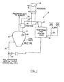
- the drawings depict a reliable, relatively low-cost automated safety system 8 capable of being integrated into a plant's computer control system designed to monitor the performance of and detect impending fires and explosions in electric-utility and industrial coal pulverizers by monitoring the level of carbon monoxide (CO) and net oxygen (0 2 ) concentration in a pulverized coal mill atmosphere.
- CO carbon monoxide
- net oxygen (0 2 ) concentration in a pulverized coal mill atmosphere.
- the combined measurement of CO and 02 concentration in the mill atmosphere is used to indicate the oxidation rate of the coal to preclude spontaneous combustion. Additionally, the measurement of net 0 2 concentration, when combined with other measurements, may provide the basis for overall mill performance calculations and the quality of the pulverized coal.
- a CO/0 2 sample probe 10 is - typically placed in a coal pulverizer 12 classifier outlet zone.
- a sample of gas is drawn through the probe 10 which has a porous high temperature filter 14.
- the filter 14 is required to maintain trouble-free operation by minimizing the amount of particulate matter drawn into the analyzer.
- a suitable filter 14 for this application is of a type described in U.S. Patent No. 4,286,472.
- the air sample drawn from the coal pulverizer 12 is then analyzed for percent by volume of oxygen (0 2 ) content and CO gas concentration in ppm (parts per million) via a known oxygen and CO gas analyzer 16 designed to operate in a harsh power plant environment and having autocalibration capabilities.
- a suitable analyzer for this application is one manufactured by the Bailey Controls Company of Babcock and Wilcox and is known as the Type OL Oxygen and CO Analyzer.- This analyzer 16 has a CO range of 0-1000 ppm and an 0 2 range of 0.1-25%. Electrical signals corresponding to carbon monoxide and oxygen concentrations are respectively transmitted to a monitoring system control 18 located in the central control room along lines 20 and 22.
- CO and O 2 concentrations are displayed and/or recorded on a strip-chart recorder 24.
- net 0 2 levels represent typically 16% O 2 and normal CO levels range between 40 and 80 ppm. If the net 0 2 concentration falls below a certain predetermined level, typically 15%,and/or the amount of CO produced exceeds a predetermined rise level considered cause for concern, typically a 50 ppm/minute sudden rise; the system 8 activates audible and visible alarms 26, 28 to alert the operator who in turn may manually take corrective action to inert the pulverizer 12 or permit the automatic monitoring system 8 to continue until it initiates an automatic inert to bring the pulverizer 12 operating parameters under control.
- the monitoring and control logic assembly 18 utilizes both a net oxygen measurement provided by the analyzer 16 along line 20 as well as a carbon monoxide measurement provided along line 22 from analyzer 16, to, on the one hand, actuate alarms 26 and 28 at predetermined levels of net oxygen and predetermined rise times of carbon monoxide concentration. Also, when the net oxygen levels and the absolute carbon monoxide levels exceed certain critical limits, automatic inerting of the pulverizer 12 is accomplished by controllably opening a valve 30 which allows some inerting media such as carbon dioxide for steam to flow along a line 32 into the pulverizer 12.
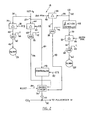
- the net oxygen measurement from line 20 is transmitted along a line 34 to a difference station 36 having a setpoint set at a predetermined net oxygen control point transmitted along line 38.
- the difference station 36 compares the actual net oxygen measurement provided by the analyzer 16 representing the net oxygen level in the pulverizer 12 and compares it with the setpoint oxygen level which, in the present situation, is set at 15%.
- the present setpoint of 15Z is based on the assumption that the typical atmosphere in the pulverizer representative of normal conditions is approximately 16% and the initial alarm condition is desired to be a warning indicative of potential problem areas.
- the difference station 36 thus compares the two signals and provides an error signal along line 40 which is one input of an AND gate 42.
- the other input of the AND gate 42 is provided by a constant negative signal from a predetermined source along line 44.
- a positive level error signal will be transmitted along line 40 to the AND gate 42 which then will fail to provide any control signal along line 46, failing to actuate the alarm 26.
- the output along line 40 becomes negative and,in combination with the constant negative signal along line 44, will result in a conduction of the AND gate 42, causing a control signal to be transmitted along line 46 to the alarm 26 to thus actuate it and provide an indication of potential problems in the pulverizer 12 atmosphere.
- the measured carbon monoxide signal transmitted along line 22 may also provide an actuation of the alternate alarm 28.
- the measured carbon monoxide signal is transmitted to a derivative action controller 48 which will be sensitive to any variations in the carbon monoxide level and will effectively provide an output signal along line 50'indicative of the slope or rate of change of the carbon monoxide level in the pulverizing mill 12.
- the output of the derivative action controller 48 is transmitted to a difference station 52 having a predetermined setpoint along line 54 indicative of a rate of carbon monoxide change which would indicate coal ignition in the pulverizer 12. Such a rate of change is typically taken to be a 50 ppm/minute rate of carbon monoxide change.
- the output of the difference station 52 is transmitted along the line 56 to an AND gate 58 having a second input of a constant negative value provided along line 60.
- the rate of carbon monoxide change normally stays below the 50 ppm/minute setpoint resulting in a negative output signal from the difference station 52.
- the signal transmitted along line 56 turns positive, causing the AND gate 58 to start conducting a control signal along line 62 to the alarm 28 actuating the alarm 28 to indicate a potentially hazardous atmosphere in the pulverizer 12.
- Automatic inerting of the pulverizer 12 is actuated by a difference station 64 which has a setpoint provided to it along line 66 having a net oxygen level significantly lower than the setpoint level provided to difference station 36.
- the difference station 64 has a net oxygen setpoint of 9%.
- the net oxygen level measured and transmitted to the difference station 64 will exceed the 9% setpoint and the error signal produced by the difference station 64 will be a positive level signal transmitted along line 68 to an AND gate 70.
- the other input of the AND gate 70 is provided by a constant negative level signal transmitted to the AND gate 70 along line 72.
- the inputs to the AND gate 70 will be positive and negative, providing no control signal from the output of the AND gate along line 74.
- the output of the difference station 64 turns negative, providing two negative inputs to the AND gate 70 and resulting in a control signal along line 74 being transmitted to a switching circuit 76.
- the switching circuit 76 is a normally open circuit, preventing the signal transmitted from a controller 78 from reaching the control valve 30.
- the switching circuit 76 changes to a closed-circuit condition, turning over control of the valve 30 to the controller 78.
- the controller 78 has an input signal indicative of the actual net oxygen level in the pulverizer 12 which is provided by a parallel line. 80, paralleling the net oxygen signal in line 20.
- the setpoint of the' controller is provided along line 82 from some predetermined setpoint station and is typically set at a 12% level.
- the controller 78 will open valve 30, causing an inerting atmosphere, such as carbon dioxide, to be delivered to the pulverizer 12 until a somewhat normal ambient is reached close to the setpoint level of 12%
- the reason for keeping the setpoint of the controller 78 at a somewhat lower than typically normal atmosphere is to minimize the shock to the pulverizer 12 due to the inerting process.
- the switching circuit is then switched back to its normally open condition by a reset signal provided along line 84 from either a manual source or an automatic source which can be tied to some parameter indicative of the reestablishment of normal ambient conditions in the pulverizer 12.
- the actuation of the automatic inerting means is also alternatively done upon the sensing of a predetermined absolute level of carbon monoxide in the pulverizer 12.
- the carbon monoxide signal normally provided along line 22 is tapped by a line 86 to provide one input of a difference station 88.
- the setpoint of the difference station 88 is provided along line 90 from a predetermined setpoint station typically set at an absolute carbon monoxide level of 200 ppm.
- a positive error signal will be transmitted by the difference station 88 along line 92 to an AND gate 94.
- the other input to AND gate 94 is provided by a line 96 connected to a constant negative level source.
- opposite polarity signals are provided to the AND gate 94, preventing the establishment of any control signal along line 98 from the AND gate 94.
- the error signal transmitted to the AND gate 94 turns negative, causing the conduction of the AND gate 94 and the establishment of a control signal along line 98 to the switching circuit 76.
- this causes the switching circuit 76 to become conductive, turning control of the valve 30 over to the controller 78.
- automatic inerting of the pulverizer 12 occurs until a reset signal is established along line 84, causing the switching circuit 76 to again become non-conductive and causing the valve 30 to switch its normally closed position.
Landscapes
- Engineering & Computer Science (AREA)
- Food Science & Technology (AREA)
- Chemical & Material Sciences (AREA)
- Combustion & Propulsion (AREA)
- Mechanical Engineering (AREA)
- General Engineering & Computer Science (AREA)
- Disintegrating Or Milling (AREA)
- Testing And Monitoring For Control Systems (AREA)
- Crushing And Grinding (AREA)
Applications Claiming Priority (2)
| Application Number | Priority Date | Filing Date | Title |
|---|---|---|---|
| US51935283A | 1983-08-01 | 1983-08-01 | |
| US519352 | 1983-08-01 |
Publications (4)
| Publication Number | Publication Date |
|---|---|
| EP0132974A2 true EP0132974A2 (fr) | 1985-02-13 |
| EP0132974A3 EP0132974A3 (en) | 1985-11-21 |
| EP0132974B1 EP0132974B1 (fr) | 1989-03-01 |
| EP0132974B2 EP0132974B2 (fr) | 1992-09-02 |
Family
ID=24067930
Family Applications (1)
| Application Number | Title | Priority Date | Filing Date |
|---|---|---|---|
| EP84304640A Expired EP0132974B2 (fr) | 1983-08-01 | 1984-07-06 | Systèmes de sécurité pour broyeuses à charbon |
Country Status (12)
| Country | Link |
|---|---|
| EP (1) | EP0132974B2 (fr) |
| JP (1) | JPS60143844A (fr) |
| KR (1) | KR900002655B1 (fr) |
| AU (1) | AU3131384A (fr) |
| BR (1) | BR8403542A (fr) |
| CA (1) | CA1229327A (fr) |
| DE (1) | DE3476851D1 (fr) |
| ES (1) | ES534210A0 (fr) |
| HK (1) | HK96689A (fr) |
| IN (1) | IN162793B (fr) |
| MX (1) | MX160409A (fr) |
| SG (1) | SG63889G (fr) |
Cited By (12)
| Publication number | Priority date | Publication date | Assignee | Title |
|---|---|---|---|---|
| EP0244074A3 (en) * | 1986-04-29 | 1988-08-10 | The Babcock & Wilcox Company | Safety systems for coal pulverizing mills |
| WO1988006920A1 (fr) * | 1987-03-18 | 1988-09-22 | Combustion Engineering, Inc. | Systeme d'extinction d'incendie et d'inactivation pour pulverisateur de charbon |
| US4778113A (en) * | 1986-04-29 | 1988-10-18 | The Babcock & Wilcox Company | Apparatus for monitoring low level combustibles |
| US4846410A (en) * | 1986-04-26 | 1989-07-11 | The Babcock & Wilcox Company | Apparatus for monitoring low-level combustibles |
| CN109696524A (zh) * | 2019-01-15 | 2019-04-30 | 华电电力科学研究院有限公司 | 一种用于防爆的磨煤机出口o2在线监测装置及使用方法 |
| CN112371317A (zh) * | 2020-10-22 | 2021-02-19 | 徐州赛森电子自动化技术有限公司 | 一种磨煤机自燃保护装置 |
| CN113310778A (zh) * | 2021-05-06 | 2021-08-27 | 安徽汽车职业技术学院 | 一种用于煤粉制备动态co检测装置 |
| CN116060200A (zh) * | 2023-03-06 | 2023-05-05 | 北京博数智源人工智能科技有限公司 | 一种火电站磨煤机的爆燃预警方法及系统 |
| CN116060201A (zh) * | 2023-03-08 | 2023-05-05 | 北京博数智源人工智能科技有限公司 | 一种火电站磨煤机爆燃监测异常定位识别方法及系统 |
| CN117463490A (zh) * | 2023-10-31 | 2024-01-30 | 山东日照发电有限公司 | 一种磨煤机安全控制系统 |
| CN118681677A (zh) * | 2024-07-09 | 2024-09-24 | 西安热工研究院有限公司 | 一种中速磨煤机出力特性评估方法、系统、设备、介质及产品 |
| CN120155291A (zh) * | 2025-05-16 | 2025-06-17 | 安徽光智科技有限公司 | 磨煤机出口温度控制方法、装置、系统及磨煤机设备 |
Families Citing this family (8)
| Publication number | Priority date | Publication date | Assignee | Title |
|---|---|---|---|---|
| JP4551101B2 (ja) * | 2004-02-27 | 2010-09-22 | 三菱重工業株式会社 | ミルイナート酸素濃度測定装置、ミルイナート酸素供給装置およびミルイナート酸素濃度測定方法 |
| LU91451B1 (en) * | 2008-06-02 | 2009-12-03 | Wurth Paul Sa | Method for producing pulverized coal |
| KR101118323B1 (ko) * | 2011-11-10 | 2012-03-09 | 도원기술 주식회사 | 석탄 발화 조기 경보 시스템 |
| JP5949414B2 (ja) * | 2012-10-05 | 2016-07-06 | 新日鐵住金株式会社 | 粉砕プラント排ガス制御装置、粉砕プラント排ガス制御方法、及びコンピュータプログラム |
| JP6011933B2 (ja) * | 2012-11-26 | 2016-10-25 | 株式会社日向製錬所 | 微粉炭ミル系設備の炭塵発火防止システム及び炭塵発火防止方法 |
| CN111495565A (zh) * | 2020-04-27 | 2020-08-07 | 安徽工业大学 | 一种发电机组燃煤锅炉的磨煤机防爆检测系统及方法 |
| CN115355941A (zh) * | 2022-07-07 | 2022-11-18 | 安诺克斯(北京)环境科技有限公司 | 一种煤粉制备安全监测方法及煤粉制备系统 |
| CN121103507B (zh) * | 2025-11-13 | 2026-02-17 | 浙江丰利粉碎设备有限公司 | 一种竹粉粉碎加工成套机组控制方法及系统 |
Family Cites Families (9)
| Publication number | Priority date | Publication date | Assignee | Title |
|---|---|---|---|---|
| US3237634A (en) * | 1966-03-01 | Process control system | ||
| US2799848A (en) * | 1953-12-17 | 1957-07-16 | Glantz Lester Murray | Two-level control system |
| GB977385A (en) * | 1960-05-23 | 1964-12-09 | Elliott Brothers London Ltd | Improvements in or relating to electrical warning systems |
| US3419772A (en) * | 1964-09-25 | 1968-12-31 | Leeds & Northrup Co | Probabilistic and deterministic filter for control systems |
| US3740739A (en) * | 1971-11-30 | 1973-06-19 | Dresser Ind | Well monitoring and warning system |
| JPS575851U (fr) * | 1980-06-09 | 1982-01-12 | ||
| JPS5820247A (ja) * | 1981-07-30 | 1983-02-05 | バブコツク日立株式会社 | ミル内の発火検知方法 |
| JPS5929052A (ja) * | 1982-08-09 | 1984-02-16 | バブコツク日立株式会社 | パイライトボツクスの発火を防止する粉砕装置 |
| GB2127605B (en) * | 1982-09-07 | 1986-09-24 | Vickers Shipbuilding & Eng | Portable hazard warning apparatus |
-
1984
- 1984-05-17 KR KR1019840004571A patent/KR900002655B1/ko not_active Expired
- 1984-06-25 CA CA000457368A patent/CA1229327A/fr not_active Expired
- 1984-06-27 IN IN448/CAL/84A patent/IN162793B/en unknown
- 1984-07-06 EP EP84304640A patent/EP0132974B2/fr not_active Expired
- 1984-07-06 DE DE8484304640T patent/DE3476851D1/de not_active Expired
- 1984-07-11 ES ES534210A patent/ES534210A0/es active Granted
- 1984-07-12 BR BR8403542A patent/BR8403542A/pt not_active IP Right Cessation
- 1984-07-13 MX MX202017A patent/MX160409A/es unknown
- 1984-07-30 AU AU31313/84A patent/AU3131384A/en not_active Abandoned
- 1984-08-01 JP JP59160314A patent/JPS60143844A/ja active Granted
-
1989
- 1989-09-15 SG SG638/89A patent/SG63889G/en unknown
- 1989-12-07 HK HK966/89A patent/HK96689A/en not_active IP Right Cessation
Cited By (15)
| Publication number | Priority date | Publication date | Assignee | Title |
|---|---|---|---|---|
| US4846410A (en) * | 1986-04-26 | 1989-07-11 | The Babcock & Wilcox Company | Apparatus for monitoring low-level combustibles |
| US4778113A (en) * | 1986-04-29 | 1988-10-18 | The Babcock & Wilcox Company | Apparatus for monitoring low level combustibles |
| AU591260B2 (en) * | 1986-04-29 | 1989-11-30 | Babcock & Wilcox Co., The | Apparatus and method for monitoring low level combustibles |
| EP0244074A3 (en) * | 1986-04-29 | 1988-08-10 | The Babcock & Wilcox Company | Safety systems for coal pulverizing mills |
| WO1988006920A1 (fr) * | 1987-03-18 | 1988-09-22 | Combustion Engineering, Inc. | Systeme d'extinction d'incendie et d'inactivation pour pulverisateur de charbon |
| CN109696524B (zh) * | 2019-01-15 | 2023-11-24 | 华电电力科学研究院有限公司 | 一种用于防爆的磨煤机出口o2在线监测装置及使用方法 |
| CN109696524A (zh) * | 2019-01-15 | 2019-04-30 | 华电电力科学研究院有限公司 | 一种用于防爆的磨煤机出口o2在线监测装置及使用方法 |
| CN112371317A (zh) * | 2020-10-22 | 2021-02-19 | 徐州赛森电子自动化技术有限公司 | 一种磨煤机自燃保护装置 |
| CN113310778B (zh) * | 2021-05-06 | 2022-05-17 | 安徽汽车职业技术学院 | 一种用于煤粉制备动态co检测装置 |
| CN113310778A (zh) * | 2021-05-06 | 2021-08-27 | 安徽汽车职业技术学院 | 一种用于煤粉制备动态co检测装置 |
| CN116060200A (zh) * | 2023-03-06 | 2023-05-05 | 北京博数智源人工智能科技有限公司 | 一种火电站磨煤机的爆燃预警方法及系统 |
| CN116060201A (zh) * | 2023-03-08 | 2023-05-05 | 北京博数智源人工智能科技有限公司 | 一种火电站磨煤机爆燃监测异常定位识别方法及系统 |
| CN117463490A (zh) * | 2023-10-31 | 2024-01-30 | 山东日照发电有限公司 | 一种磨煤机安全控制系统 |
| CN118681677A (zh) * | 2024-07-09 | 2024-09-24 | 西安热工研究院有限公司 | 一种中速磨煤机出力特性评估方法、系统、设备、介质及产品 |
| CN120155291A (zh) * | 2025-05-16 | 2025-06-17 | 安徽光智科技有限公司 | 磨煤机出口温度控制方法、装置、系统及磨煤机设备 |
Also Published As
| Publication number | Publication date |
|---|---|
| KR850001561A (ko) | 1985-03-30 |
| KR900002655B1 (ko) | 1990-04-21 |
| ES8504487A1 (es) | 1985-05-16 |
| EP0132974B2 (fr) | 1992-09-02 |
| MX160409A (es) | 1990-02-19 |
| DE3476851D1 (en) | 1989-04-06 |
| JPH0128613B2 (fr) | 1989-06-05 |
| BR8403542A (pt) | 1985-06-25 |
| AU3131384A (en) | 1985-02-07 |
| ES534210A0 (es) | 1985-05-16 |
| SG63889G (en) | 1990-01-26 |
| JPS60143844A (ja) | 1985-07-30 |
| CA1229327A (fr) | 1987-11-17 |
| EP0132974A3 (en) | 1985-11-21 |
| HK96689A (en) | 1989-12-15 |
| IN162793B (fr) | 1988-07-09 |
| EP0132974B1 (fr) | 1989-03-01 |
Similar Documents
| Publication | Publication Date | Title |
|---|---|---|
| EP0132974B1 (fr) | Systèmes de sécurité pour broyeuses à charbon | |
| US4653698A (en) | Safety system for coal pulverizers | |
| EP0244074B1 (fr) | Systèmes de sécurité pour broyeurs pulvériseurs à charbon | |
| EP0305446B1 (fr) | Systeme d'extinction d'incendie et d'inactivation pour pulverisateur de charbon | |
| US4846410A (en) | Apparatus for monitoring low-level combustibles | |
| US9841400B2 (en) | System and method for detecting smoldering in processes with continuous air flow | |
| Barton | Dust explosion prevention and protection | |
| CN102725571B (zh) | 用于在现场过程分析仪中使用的火焰安全系统 | |
| EP2777813B1 (fr) | Surveillance de pulvérisateur | |
| US4778113A (en) | Apparatus for monitoring low level combustibles | |
| US3867640A (en) | Dust sampling system | |
| JPS6149569B2 (fr) | ||
| CN111495565A (zh) | 一种发电机组燃煤锅炉的磨煤机防爆检测系统及方法 | |
| WO2015036725A1 (fr) | Capteur de gaz | |
| RU2005102813A (ru) | Устройство для систем обеспечения безопасности при эксплуатации укрытий на установках | |
| US3557725A (en) | Furnace emission control system | |
| US4099165A (en) | Fire detection apparatus in a preheater | |
| EP0314133B1 (fr) | Appareil de compression de fluides avec refroidissement à l'huile | |
| JP3376530B2 (ja) | 電気集塵器ホッパ内のダスト状態監視装置 | |
| JP7828825B2 (ja) | ガスバーナシステムの運転を監視する方法およびガスバーナシステム | |
| JPH0226188B2 (fr) | ||
| JPH0333003Y2 (fr) | ||
| JPS5823300B2 (ja) | 可燃性粉体輸送装置に於ける安全装置 | |
| CS210949B1 (cs) | Způsob zjišťování přerušeni dodávky paliva do fluidního ohniště a zařízení k provádění tohoto způsobu | |
| CA2173496A1 (fr) | Dispositif permettant d'ecarter tout risque d'incendies dus a la combustion ou a l'incandescence de particules dans une canalisation |
Legal Events
| Date | Code | Title | Description |
|---|---|---|---|
| PUAI | Public reference made under article 153(3) epc to a published international application that has entered the european phase |
Free format text: ORIGINAL CODE: 0009012 |
|
| AK | Designated contracting states |
Designated state(s): DE FR GB IT |
|
| PUAL | Search report despatched |
Free format text: ORIGINAL CODE: 0009013 |
|
| AK | Designated contracting states |
Designated state(s): DE FR GB IT |
|
| 17P | Request for examination filed |
Effective date: 19860509 |
|
| 17Q | First examination report despatched |
Effective date: 19871014 |
|
| ITF | It: translation for a ep patent filed | ||
| GRAA | (expected) grant |
Free format text: ORIGINAL CODE: 0009210 |
|
| AK | Designated contracting states |
Kind code of ref document: B1 Designated state(s): DE FR GB IT |
|
| REF | Corresponds to: |
Ref document number: 3476851 Country of ref document: DE Date of ref document: 19890406 |
|
| ET | Fr: translation filed | ||
| PLBI | Opposition filed |
Free format text: ORIGINAL CODE: 0009260 |
|
| 26 | Opposition filed |
Opponent name: KLOECKNER-HUMBOLDT-DEUTZ AG, KOELN C/O KHD HUMBOLD Effective date: 19891125 |
|
| ITTA | It: last paid annual fee | ||
| REG | Reference to a national code |
Ref country code: GB Ref legal event code: 732 |
|
| ITF | It: translation for a ep patent filed | ||
| PUAH | Patent maintained in amended form |
Free format text: ORIGINAL CODE: 0009272 |
|
| STAA | Information on the status of an ep patent application or granted ep patent |
Free format text: STATUS: PATENT MAINTAINED AS AMENDED |
|
| 27A | Patent maintained in amended form |
Effective date: 19920902 |
|
| AK | Designated contracting states |
Kind code of ref document: B2 Designated state(s): DE FR GB IT |
|
| ET3 | Fr: translation filed ** decision concerning opposition | ||
| PGFP | Annual fee paid to national office [announced via postgrant information from national office to epo] |
Ref country code: FR Payment date: 19960617 Year of fee payment: 13 |
|
| PGFP | Annual fee paid to national office [announced via postgrant information from national office to epo] |
Ref country code: DE Payment date: 19960618 Year of fee payment: 13 |
|
| PGFP | Annual fee paid to national office [announced via postgrant information from national office to epo] |
Ref country code: GB Payment date: 19960626 Year of fee payment: 13 |
|
| PG25 | Lapsed in a contracting state [announced via postgrant information from national office to epo] |
Ref country code: GB Free format text: LAPSE BECAUSE OF NON-PAYMENT OF DUE FEES Effective date: 19970706 |
|
| GBPC | Gb: european patent ceased through non-payment of renewal fee |
Effective date: 19970706 |
|
| PG25 | Lapsed in a contracting state [announced via postgrant information from national office to epo] |
Ref country code: FR Free format text: LAPSE BECAUSE OF NON-PAYMENT OF DUE FEES Effective date: 19980331 |
|
| PG25 | Lapsed in a contracting state [announced via postgrant information from national office to epo] |
Ref country code: DE Free format text: LAPSE BECAUSE OF NON-PAYMENT OF DUE FEES Effective date: 19980401 |
|
| REG | Reference to a national code |
Ref country code: FR Ref legal event code: ST |