EP0133002B1 - Processeur adaptatif de signal radar - Google Patents
Processeur adaptatif de signal radar Download PDFInfo
- Publication number
- EP0133002B1 EP0133002B1 EP84304982A EP84304982A EP0133002B1 EP 0133002 B1 EP0133002 B1 EP 0133002B1 EP 84304982 A EP84304982 A EP 84304982A EP 84304982 A EP84304982 A EP 84304982A EP 0133002 B1 EP0133002 B1 EP 0133002B1
- Authority
- EP
- European Patent Office
- Prior art keywords
- region
- signal
- filter
- clutter
- generator
- Prior art date
- Legal status (The legal status is an assumption and is not a legal conclusion. Google has not performed a legal analysis and makes no representation as to the accuracy of the status listed.)
- Expired
Links
Images


Classifications
-
- G—PHYSICS
- G01—MEASURING; TESTING
- G01S—RADIO DIRECTION-FINDING; RADIO NAVIGATION; DETERMINING DISTANCE OR VELOCITY BY USE OF RADIO WAVES; LOCATING OR PRESENCE-DETECTING BY USE OF THE REFLECTION OR RERADIATION OF RADIO WAVES; ANALOGOUS ARRANGEMENTS USING OTHER WAVES
- G01S7/00—Details of systems according to groups G01S13/00, G01S15/00, G01S17/00
- G01S7/02—Details of systems according to groups G01S13/00, G01S15/00, G01S17/00 of systems according to group G01S13/00
- G01S7/28—Details of pulse systems
- G01S7/285—Receivers
- G01S7/292—Extracting wanted echo-signals
- G01S7/2923—Extracting wanted echo-signals based on data belonging to a number of consecutive radar periods
-
- G—PHYSICS
- G01—MEASURING; TESTING
- G01S—RADIO DIRECTION-FINDING; RADIO NAVIGATION; DETERMINING DISTANCE OR VELOCITY BY USE OF RADIO WAVES; LOCATING OR PRESENCE-DETECTING BY USE OF THE REFLECTION OR RERADIATION OF RADIO WAVES; ANALOGOUS ARRANGEMENTS USING OTHER WAVES
- G01S13/00—Systems using the reflection or reradiation of radio waves, e.g. radar systems; Analogous systems using reflection or reradiation of waves whose nature or wavelength is irrelevant or unspecified
- G01S13/02—Systems using reflection of radio waves, e.g. primary radar systems; Analogous systems
- G01S13/50—Systems of measurement based on relative movement of target
- G01S13/52—Discriminating between fixed and moving objects or between objects moving at different speeds
- G01S13/522—Discriminating between fixed and moving objects or between objects moving at different speeds using transmissions of interrupted pulse modulated waves
- G01S13/524—Discriminating between fixed and moving objects or between objects moving at different speeds using transmissions of interrupted pulse modulated waves based upon the phase or frequency shift resulting from movement of objects, with reference to the transmitted signals, e.g. coherent MTi
- G01S13/5244—Adaptive clutter cancellation
Definitions
- This invention relates to radar signal processing apparatus and, more particularly, an adaptive radar signal processing apparatus, in which undesired signals are suppressed in an adaptive radar signal processing by switching filter characteristics according to various regions responsible for generation of undesired signals.
- X(I) represents an input signal
- W(I) is a filter constant
- Y(m) is an output signal.
- m, I and N are integers
- N represents the number of digital filter stages
- the input/output signal and filter coefficients are complex numbers.
- Figure 1 shows the structure of a conventional digital filter.
- signals involved are all complex numbers
- arithmetic units are all complex number arithmetic units.
- the circuit illustrated comprises an input terminal 100, memories 111-1, 111-2, ..., 111-(N-1),weighting multipliers 121-1, 121-2, ..., 121-N, filter coefficient application terminals 131-1, 131-2, ..., 131-N, an adder 140 and an output terminal 150.
- the memories have a memory capacity required to store all reflected signals (digital signals) which are obtained, as radar reception signals, successively for each transmission pulse.
- the frequency response characteristics of a digital filter are determined definitely by giving a filter coefficient (i.e. W(I) in Figure 1), and various digital filters can be realized which have an MTI (Marring Target Indication) cancellation function and a DFT (Dispersive Fourier Transform) function in radars to obtain desired response characteristics within the range of the freedom of the filter (i.e., number N of filter stages).
- W(I) filter coefficient
- various digital filters can be realized which have an MTI (Marring Target Indication) cancellation function and a DFT (Dispersive Fourier Transform) function in radars to obtain desired response characteristics within the range of the freedom of the filter (i.e., number N of filter stages).
- the radar reception signal contains a signal reflected from the ground, buildings, etc. referred to as stationary clutter), a signal reflected from rain droplets, clouds, etc. (referred to a moving clutter), a signal reflected from an aircraft (referred to as target or desired signal) and a noise signal.
- the stationary clutter has a Doppler spectrum centered on zero Doppler frequency.
- the moving clutter and desired signals respectively cover a wide range of frequencies about the zero Doppler frequency.
- Doppler spectra of these signals are exemplified in Figure 2 where 200 represents a stationary clutter spectrum 210 a moving clutter spectrum, and 220 a spectrum of the desired signal.
- the stationary and moving clutters both being simply referred to as clutter
- the noise signal stand for undesired signals in the radar reception signal and generally, the former is far more intensive than the latter.
- a filter characteristic which sufficiently can suppress the undesired signal attributable to the clutter region to maximize the degree of S/C improvement (i.e., the degree of input/output improvement in the ratio of the desired signal to the clutter). More specifically, since a signal representative of the stationary clutter attributable to the stationary clutter region is strong, it is necessary for the filter to have, for the purpose of suppressing the stationary clutter signal, a filter characteristic which has null filtering at the zero frequency pointed and has sufficiently low side lobe levels in the neighborhood of the zero frequency so that sufficient suppression can be obtained. For the moving clutter region, since the moving clutter prevails over a wide range, it is necessary to provide a uniformly low side lobe characteristic.
- a filter characteristic which maximize the S/N improvement degree (i.e., the degree of input/output improvement in the ratio of the desired signal to the noise), and hence a DFT filter is required.
- the filter coefficient has been fixed, and the filter has an MTI cancellation function, a DFTfunction, a digital filtering function or a function of MTI cancellation and digital filtering in combination.
- the MTI cancellation is effective for the stationary clutter region but is not suited to a composite clutter region covering both the stationary clutter and moving clutter.
- the DFT is best suited to the clear region with the maximum S/N improvement degree.
- the DFT fails to provide necessary suppression for the stationary and moving clutter regions since the side lobe is high in these regions.
- the combination of the MTI cancellation and digital filtering is effective for the stationary and moving clutter regions, but is not suited for the clear region since the maximum S/N improvement degree cannot be obtained.
- the filter characteristic can be so determined as to be suited for the stationary clutter region, moving clutter region and clear region, but the optimum filter characteristic is not the same in the individual regions.
- the prior art digital filter because of its fixed filter coefficient, is not suited for some regions although suited for the other regions.
- An adaptive radar signal processing apparatus for a radar system is known from Proceedings of the IEEE 1981, National Aerospace and Electronics Conference, 19-21 May 1981, Vol. 2, pages 800-807.
- This reference discloses data recording in relation to a restricted area of space for efficiency of data analysis and clutter suppression, using an adaptive moving target indicator and an adaptive polarization canceller.
- the object of the present invention is to provide an improved apparatus capable of providing suppression of undesired signals which is specifically adapted to each of the stationary clutter region, the moving clutter region and the clear region.
- the adaptive radar signal processing apparatus for a radar system is defined in the claim below.
- FIG. 3 shows the construction of the embodiment.
- the illustrated embodiment comprises first to (N-1) sweep memories 311-1 to 311-(N-1), weighting multipliers (weight applying units) 321-1 to 321-N, a weight coefficient generator 340, a control signal generator 350, a region discriminator 360, and an adder 380.
- Each of the sweep memories 311-1 to 311-(N-1) has a memory capacity in excess of the number of data pieces per transmission pulse multiplied by the amplitude bit number.
- An input terminal 300 for reception of a complex signal is connected to the first sweep memory 311-1.
- the second sweep memory 311-2 and weight applying unit 321-2 are connected to the first sweep memory 311-1, and the other sweep memories and weight applying units are connected similarly.
- the weight coefficient generator 340 provides a weighting coefficient (i.e., a filter coefficient determining the filter characteristic) corresponding to each region to respective weight coefficient input terminals 331-1 to 331-N, of each of the weight applying units 321-1 to 321-N.
- the control signal generator 350 generates a weight coefficient switching signal to the weight coefficient generator 340.
- the region discriminator 360 discriminates a region in accordance with an input signal supplied to its input signal terminal 370.
- the adder 380 adds together the output signals of the individual weight applying units 321-1 to 321-N.
- An output terminal 390 is connected to the adder 380.
- the input signal to the apparatus input terminal 300 is subjected to a predetermined processing by a circuit (not shown) and applied to the terminal 370.
- the above construction of the embodiment of the invention effects the switching of filter characteristics as follows.
- the control signal generator 350 controls the weight coefficient generator 340 for the switching of the filter coefficients such that an optimum filter characteristic is provided for each region according to a region discrimination signal generated from the region discriminator 360 (representing either the stationary clutter region, moving clutter region, or clear region).
- the filter coefficient is selected such as to provide the combination of the MTI cancellation and digital filtering, thereby ensuring that the high intensity stationary clutter can be suppressed sufficiently.
- the filter coefficient is selected such as to provide a low side lobe characterstic.
- the filter coefficient selection is such as to provide a DFT function for maximizing the S/ N ratio.
- the filter coefficient is selected to provide the combination of the MTI cancellation and digital filtering.
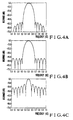
- Figure 4A to 4C show examples of the digital filter characteristic. Specifically, Figure 4A shows the characteristic of the combination of the MTI cancellation and digital filtering. Figure 4B shows the characteristic of the low side lobe digital filter. Figure 4C shows the characteristic of the DFT digital filtering.
- optimum filter characteristics can be obtained for the individual stationary clutter region, moving clutter region, clear region, etc., thereby ensuring that the undesired signals can be effectively suppressed and satisfactory detection of targets can be accomplished.
Landscapes
- Engineering & Computer Science (AREA)
- Radar, Positioning & Navigation (AREA)
- Remote Sensing (AREA)
- Computer Networks & Wireless Communication (AREA)
- Physics & Mathematics (AREA)
- General Physics & Mathematics (AREA)
- Radar Systems Or Details Thereof (AREA)
- Filters That Use Time-Delay Elements (AREA)
Claims (1)
- Appareil de traitement adaptatif d'un signal radar pour un système de radar, comprenant une unité de mémoire comportant une multitude de mémoire (311-1-311(N-1)) ayant une capacité prédéterminée de mémorisation, afin de stocker successivement un signal d'entrée à l'appareil dans les mémoires et de lire des signaux dans les mémoires, un générateur (340) de coefficient de pondération contenant des coefficients de pondération, des ensembles de pondération (321-1-321-N) pour appliquer des coefficients de pondération individuels à partir du générateur (340) aux signaux lus, et un additioneur (380) pour ajouter ensemble les sorties des ensembles de pondération (321-1-321-N) et produire un signal desortie de l'appareil, caractérisé par un discriminateur de zone (360) qui récoit un signal d'entrée et fait une discriminaton entre une zone contenant des objets d'un fouillis d'écho fixe, une zone contenant des objets d'un fouillis d'écho en mouvement, et une zone ne contenant ni des objets de fouillis d'écho fixe ni des objets de fouillis d'écho en mouvement, et un générateur (350) de signaux de commande répondant à une sortie du discriminateur de zone, pour produire un signal de commande afin de contrôler les coefficients de pondération applicables aux ensembles de pondération en fonction des zones ayant fait l'objet d'une discrimination, le générateur (340) de coefficient de pondération ayant des coefficients de pondération correspondant aux zones, et pour fournir un signal de commutation de coefficient de pondération au générateur de coefficient de pondération, ce qui permet d'adapter aux zones ayant fait l'objet d'une discrimination la suppression des signaux indésirés.
Applications Claiming Priority (2)
| Application Number | Priority Date | Filing Date | Title |
|---|---|---|---|
| JP58133345A JPS6024477A (ja) | 1983-07-21 | 1983-07-21 | レ−ダ−信号処理装置 |
| JP133345/83 | 1983-07-21 |
Publications (3)
| Publication Number | Publication Date |
|---|---|
| EP0133002A2 EP0133002A2 (fr) | 1985-02-13 |
| EP0133002A3 EP0133002A3 (en) | 1986-12-03 |
| EP0133002B1 true EP0133002B1 (fr) | 1989-10-11 |
Family
ID=15102545
Family Applications (1)
| Application Number | Title | Priority Date | Filing Date |
|---|---|---|---|
| EP84304982A Expired EP0133002B1 (fr) | 1983-07-21 | 1984-07-20 | Processeur adaptatif de signal radar |
Country Status (4)
| Country | Link |
|---|---|
| US (1) | US4658255A (fr) |
| EP (1) | EP0133002B1 (fr) |
| JP (1) | JPS6024477A (fr) |
| DE (1) | DE3480122D1 (fr) |
Families Citing this family (34)
| Publication number | Priority date | Publication date | Assignee | Title |
|---|---|---|---|---|
| JP2601837B2 (ja) * | 1987-09-14 | 1997-04-16 | 株式会社東芝 | レーダ装置 |
| US4890113A (en) * | 1987-12-09 | 1989-12-26 | Westinghouse Electric Corp. | Second time around clutter cancellation system |
| FR2628909B1 (fr) * | 1988-03-18 | 1990-07-13 | Thomson Csf | Procede et dispositifs de translation le long de l'axe des frequences du module de la fonction de transfert d'un filtre |
| JP2550706B2 (ja) * | 1989-05-31 | 1996-11-06 | 日本電気株式会社 | ディジタルパルス圧縮装置 |
| GB2273014B (en) * | 1992-11-27 | 1996-10-30 | Samsung Electronics Co Ltd | Clutter canceler of a pulse radar system |
| GB2299909B (en) * | 1995-04-11 | 1999-11-24 | Commw Of Australia | Improved radar target detection |
| US20040151241A1 (en) * | 2003-02-03 | 2004-08-05 | Tsutomu Shimotoyodome | Signal generator using IIR type digital filter and its output stopping method |
| US8902100B1 (en) | 2008-03-07 | 2014-12-02 | Rockwell Collins, Inc. | System and method for turbulence detection |
| US8203480B1 (en) | 2003-07-31 | 2012-06-19 | Rockwell Collins, Inc. | Predictive and adaptive weather radar detection system and method |
| US7808422B1 (en) | 2003-07-31 | 2010-10-05 | Rockwell Collins, Inc. | Predictive and adaptive weather radar detection system and method |
| US7483931B2 (en) * | 2004-01-30 | 2009-01-27 | Oki Electric Industry Co., Ltd. | Signal generator using IIR type digital filter; and method of generating, supplying, and stopping its output signal |
| US9864055B1 (en) | 2014-03-12 | 2018-01-09 | Rockwell Collins, Inc. | Weather radar system and method for detecting a high altitude crystal cloud condition |
| US9244157B1 (en) | 2008-03-07 | 2016-01-26 | Rockwell Collins, Inc. | Weather radar threat depiction system and method |
| US9244166B1 (en) | 2008-03-07 | 2016-01-26 | Rockwell Collins, Inc. | System and method for ice detection |
| US9846230B1 (en) | 2013-03-15 | 2017-12-19 | Rockwell Collins, Inc. | System and method for ice detection |
| US9057773B1 (en) | 2012-12-06 | 2015-06-16 | Rockwell Collins, Inc. | Weather information display system and method |
| US9244167B1 (en) | 2008-03-07 | 2016-01-26 | Rockwell Collins, Inc. | Long range weather information display system and method |
| US20120013565A1 (en) * | 2010-07-16 | 2012-01-19 | Perceptive Pixel Inc. | Techniques for Locally Improving Signal to Noise in a Capacitive Touch Sensor |
| US9223020B1 (en) | 2010-09-28 | 2015-12-29 | Rockwell Collins, Inc. | System and method for weather detection using more than one source of radar data |
| US9823347B1 (en) | 2014-03-12 | 2017-11-21 | Rockwell Collins, Inc. | Weather radar system and method for high altitude crystal warning interface |
| US9019146B1 (en) | 2011-09-27 | 2015-04-28 | Rockwell Collins, Inc. | Aviation display depiction of weather threats |
| JP5858755B2 (ja) * | 2011-11-29 | 2016-02-10 | 三菱電機株式会社 | レーダ装置 |
| US9116244B1 (en) | 2013-02-28 | 2015-08-25 | Rockwell Collins, Inc. | System for and method of weather phenomenon detection using multiple beams |
| US9535158B1 (en) | 2013-11-21 | 2017-01-03 | Rockwell Collins, Inc. | Weather radar system and method with fusion of multiple weather information sources |
| US9599707B1 (en) | 2014-01-23 | 2017-03-21 | Rockwell Collins, Inc. | Weather radar system and method with path attenuation shadowing |
| RU2599054C2 (ru) * | 2014-05-19 | 2016-10-10 | Открытое акционерное общество "Равенство" (ОАО "Равенство") | Двухволновый адаптивный радиолокатор |
| US9810770B1 (en) | 2014-07-03 | 2017-11-07 | Rockwell Collins, Inc. | Efficient retrieval of aviation data and weather over low bandwidth links |
| JP6449595B2 (ja) * | 2014-08-29 | 2019-01-09 | 古野電気株式会社 | クラッタ抑圧装置及びそれを備えたレーダ装置 |
| JP6339893B2 (ja) * | 2014-08-29 | 2018-06-06 | 古野電気株式会社 | クラッタ抑圧装置及びそれを備えたレーダ装置 |
| US9869766B1 (en) | 2015-01-28 | 2018-01-16 | Rockwell Collins, Inc. | Enhancement of airborne weather radar performance using external weather data |
| US10809375B1 (en) | 2015-09-14 | 2020-10-20 | Rockwell Collins, Inc. | Radar system and method for detecting hazards associated with particles or bodies |
| US10302815B1 (en) | 2015-10-01 | 2019-05-28 | Rockwell Collins, Inc. | System and method of integrating global convective weather |
| US10494108B1 (en) | 2016-05-17 | 2019-12-03 | Rockwell Collins, Inc. | System and method for providing icing condition warnings |
| KR102103846B1 (ko) * | 2019-10-02 | 2020-04-23 | 한화시스템 주식회사 | 차세대 함정의 표적 정보 처리 장치 |
Family Cites Families (5)
| Publication number | Priority date | Publication date | Assignee | Title |
|---|---|---|---|---|
| JPS5232837B2 (fr) * | 1972-12-06 | 1977-08-24 | ||
| JPS54103689A (en) * | 1978-02-01 | 1979-08-15 | Toshiba Corp | Moving target detector |
| GB2044034B (en) * | 1979-03-10 | 1983-05-25 | Plessey Co Ltd | Adaptive mti |
| DE3243606A1 (de) * | 1982-11-25 | 1984-05-30 | Licentia Patent-Verwaltungs-Gmbh, 6000 Frankfurt | Anordnung zur radarsignalverarbeitung bei einem puls-doppler-radar |
| IT1168614B (it) * | 1983-07-15 | 1987-05-20 | Selenia Ind Elettroniche | Elaboratore digitale a mtd per radar di ricerca con banco di filtri doppler e sistema di soglie entrambi selezionabili in dipendenza del disturbo |
-
1983
- 1983-07-21 JP JP58133345A patent/JPS6024477A/ja active Pending
-
1984
- 1984-07-20 EP EP84304982A patent/EP0133002B1/fr not_active Expired
- 1984-07-20 DE DE8484304982T patent/DE3480122D1/de not_active Expired
- 1984-07-23 US US06/633,030 patent/US4658255A/en not_active Expired - Lifetime
Also Published As
| Publication number | Publication date |
|---|---|
| JPS6024477A (ja) | 1985-02-07 |
| EP0133002A3 (en) | 1986-12-03 |
| EP0133002A2 (fr) | 1985-02-13 |
| DE3480122D1 (en) | 1989-11-16 |
| US4658255A (en) | 1987-04-14 |
Similar Documents
| Publication | Publication Date | Title |
|---|---|---|
| US4658255A (en) | Adaptive radar signal processing apparatus | |
| US4137532A (en) | VIP doppler filter bank signal processor for pulse doppler radar | |
| US4533915A (en) | Radar terrain signal suppressor | |
| AU701515B2 (en) | Adaptive filtering of matched-filter data | |
| US5796779A (en) | Adaptive signal processor for non-stationary environments and method | |
| US5481270A (en) | Radar with adaptive range sidelobe suppression | |
| US5465095A (en) | Time efficient method for processing adaptive target detection thresholds in doppler radar systems | |
| US4622552A (en) | Factored matched filter/FFT radar Doppler processor | |
| US4213127A (en) | Doubly adaptive CFAR apparatus | |
| US4635063A (en) | Adaptive antenna | |
| US5179542A (en) | Signal processor | |
| EP0149981B1 (fr) | Dispositif de traitement adaptatif de signaux radar pour détecter les échos utiles et supprimer les parasites | |
| US20030198340A1 (en) | Multistage median cascaded canceller | |
| US4730189A (en) | Pulse Doppler radar with variable pulse repetition frequency | |
| CA2047813C (fr) | Procede de compensation d'acceleration au moyen de filtres adaptes | |
| EP0069415A1 (fr) | Circuit détecteur de cibles mobiles pour radar | |
| EP0132232B1 (fr) | Circuit de traitement numérique adaptatif de type MTD pour radar de surveillance, avec un banc de filtres Doppler et un dispositif à seuils pouvant à la fois être sélectionnés et dépendre des interférences | |
| EP0273970B1 (fr) | Circuit d'annulation d'echos fixes dans des intervalles de distance multiples | |
| EP0187851B1 (fr) | Dispositif adaptatif de prevision de la reverberation de surface dans un sonar bistatique | |
| US4104633A (en) | Extended target-log CFAR processor | |
| US4839655A (en) | Moving target detector signal processor enabling selected video output with smooth amplitude | |
| US4104631A (en) | Method and system for clutter blanking in a radar target processor | |
| EP0692720B1 (fr) | Corrélation de rampe pondérée et à suréchantillonnage | |
| Zverev | Digital MTI radar filters | |
| US4661816A (en) | Adaptive radar signal processor |
Legal Events
| Date | Code | Title | Description |
|---|---|---|---|
| PUAI | Public reference made under article 153(3) epc to a published international application that has entered the european phase |
Free format text: ORIGINAL CODE: 0009012 |
|
| 17P | Request for examination filed |
Effective date: 19840731 |
|
| AK | Designated contracting states |
Designated state(s): DE FR GB |
|
| PUAL | Search report despatched |
Free format text: ORIGINAL CODE: 0009013 |
|
| AK | Designated contracting states |
Kind code of ref document: A3 Designated state(s): DE FR GB |
|
| 17Q | First examination report despatched |
Effective date: 19880714 |
|
| GRAA | (expected) grant |
Free format text: ORIGINAL CODE: 0009210 |
|
| AK | Designated contracting states |
Kind code of ref document: B1 Designated state(s): DE FR GB |
|
| REF | Corresponds to: |
Ref document number: 3480122 Country of ref document: DE Date of ref document: 19891116 |
|
| ET | Fr: translation filed | ||
| PLBE | No opposition filed within time limit |
Free format text: ORIGINAL CODE: 0009261 |
|
| STAA | Information on the status of an ep patent application or granted ep patent |
Free format text: STATUS: NO OPPOSITION FILED WITHIN TIME LIMIT |
|
| 26N | No opposition filed | ||
| REG | Reference to a national code |
Ref country code: GB Ref legal event code: IF02 |
|
| PGFP | Annual fee paid to national office [announced via postgrant information from national office to epo] |
Ref country code: FR Payment date: 20030711 Year of fee payment: 20 |
|
| PGFP | Annual fee paid to national office [announced via postgrant information from national office to epo] |
Ref country code: GB Payment date: 20030716 Year of fee payment: 20 |
|
| PGFP | Annual fee paid to national office [announced via postgrant information from national office to epo] |
Ref country code: DE Payment date: 20030731 Year of fee payment: 20 |
|
| PG25 | Lapsed in a contracting state [announced via postgrant information from national office to epo] |
Ref country code: GB Free format text: LAPSE BECAUSE OF EXPIRATION OF PROTECTION Effective date: 20040719 |
|
| REG | Reference to a national code |
Ref country code: GB Ref legal event code: PE20 |