EP0133230A2 - Fixation d'une glissière à un profilé de support fixé à un plafond - Google Patents
Fixation d'une glissière à un profilé de support fixé à un plafond Download PDFInfo
- Publication number
- EP0133230A2 EP0133230A2 EP84108121A EP84108121A EP0133230A2 EP 0133230 A2 EP0133230 A2 EP 0133230A2 EP 84108121 A EP84108121 A EP 84108121A EP 84108121 A EP84108121 A EP 84108121A EP 0133230 A2 EP0133230 A2 EP 0133230A2
- Authority
- EP
- European Patent Office
- Prior art keywords
- mounting bracket
- running rail
- support profile
- profile
- ceiling
- Prior art date
- Legal status (The legal status is an assumption and is not a legal conclusion. Google has not performed a legal analysis and makes no representation as to the accuracy of the status listed.)
- Granted
Links
- 238000003780 insertion Methods 0.000 claims abstract description 14
- 230000037431 insertion Effects 0.000 claims abstract description 14
- 238000000605 extraction Methods 0.000 claims 1
- 210000002414 leg Anatomy 0.000 description 22
- 239000000463 material Substances 0.000 description 3
- 238000002347 injection Methods 0.000 description 2
- 239000007924 injection Substances 0.000 description 2
- 239000004033 plastic Substances 0.000 description 2
- 230000000284 resting effect Effects 0.000 description 2
- 239000004952 Polyamide Substances 0.000 description 1
- 238000010276 construction Methods 0.000 description 1
- 229920002647 polyamide Polymers 0.000 description 1
- 239000000725 suspension Substances 0.000 description 1
- 210000000689 upper leg Anatomy 0.000 description 1
Images
Classifications
-
- A—HUMAN NECESSITIES
- A47—FURNITURE; DOMESTIC ARTICLES OR APPLIANCES; COFFEE MILLS; SPICE MILLS; SUCTION CLEANERS IN GENERAL
- A47H—FURNISHINGS FOR WINDOWS OR DOORS
- A47H1/00—Curtain suspension devices
- A47H1/10—Means for mounting curtain rods or rails
- A47H1/104—Means for mounting curtain rods or rails for mounting curtain rails
Definitions
- the invention relates to a fastening of a running rail according to the preamble of claim 1.
- a continuous piping profile is used as the mounting element, which is naturally relatively expensive.
- the keder profile is not locked in the space between the side wall of the running rail and the associated side wall of the support profile, but is simply inserted in a clamped manner. As soon as there is little expansion play due to existing temperature differences or due to the working of components, the entire welt rail falls out.
- the present invention has for its object to develop the fastening of a running rail in a support profile of the type mentioned so that the attachment is safer and independent of changes in the support profile and the running rail and that also ensures repeated removal of the running rail from the support profile is.
- the invention is characterized in that the mounting element is a mounting bracket which can be locked in the direction of insertion with the running rail.
- the main difference between the present invention and the prior art is that not a continuous length clamping rail, e.g. of 2 - 6 m, is used, but that only a relatively short mounting bracket with a longitudinal width of about 20 mm is used, which also latches to the running rail. This makes it possible to ensure repeated removal of the mounting bracket from the support profile, because the latching on the one hand provides a secure hold for the mounting bracket and on the other hand enables it to be easily removed.
- the mounting bracket is only relatively short and therefore ensures a punctiform clamping of the running rail in the region of the support profile. In this way, any deformations of the support profile - due to a mechanical deformation of the support structure - are no longer disadvantageously passed on to the running rail, and the clamping is reliable, but can be released again at any time.
- the mounting bracket has a spring leg which is elastically bendable and at the upper, free end of which a locking body consisting of two wedge surfaces tapering towards one another is arranged.
- the mounting bracket a fork-like upper part with three - having having a mutual distance parallel legs, the two outer legs in the vertical L ijkser- stretching are formed longer than the interposed middle leg, it is achieved that the insertion of the Mounting bracket in the space between the support profile and the running rail is limited when the stop surfaces arranged on the upper ends of the outer legs strike the inside of the support profile. A further insertion of the mounting bracket is not possible, so that this ensures, among other things, that the mounting bracket does not disappear in the space and can no longer be pulled out.
- the resilient center leg resiliently retracts, so that after the locking body has been pushed in, it snaps onto a laterally attached shoulder of the running rail and at the same time strike the stop surfaces arranged on the outer legs on the inner underside of the support profile. This clearly defines the locking position of the mounting bracket.
- the part of the assembly clip arranged at the bottom in the insertion direction is formed as an elongated tongue of reduced width, on the side surfaces of which ribs are formed, and on the underside of which an elongated, incision aligned in the vertical direction is arranged.
- Flat-nose pliers are required for pulling out, the inside of one pliers half resting on the side surface of the pliers in the region of the ribs and the other plier half resting on the ribs of the tongue arranged opposite one another.
- the mounting bracket can now be easily pulled out by pulling on the flat-nose pliers, whereby the wedge surface attached to the locking body at the bottom ensures that the locking body springs back into the space between the support profile and the running rail and the locking is thus canceled.
- the incision arranged at the bottom on the underside of the tongue serves to insert the mounting bracket into the space between the support profile and the running rail by inserting the blade of a screwdriver or similar tool into the incision and carrying out the pushing motion with the screwdriver.
- the mounting bracket consists of a simple and inexpensive plastic injection molded part. About 3 pieces of mounting brackets are to be provided per running meter of support profile. The intended fastening between the support profile and the running rail is mainly used for vertical systems.
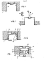
- a support profile 1 can be plastered in a flush-mounted structure 2.
- the same support profile 1 can also be used with a suspended ceiling 3.
- the ceiling hanger 4 is inserted into an upper profile groove and suspended from the ceiling with a ceiling hook 5.
- the hanging of the running rail 6 in the support profile 1 according to FIG. 3 takes place by means of a rib 11 attached laterally on the inside of the support profile, which clicks into a corresponding receptacle 12 on the side of the running rail 6. 3, the running rail 6 is first inserted into the supporting profile from below, in order then to be guided in the direction of arrow 13 with the receptacle 12 against the rib 11, as a result of which the suspension between the rib 29 of the running rail 6 and the associated rib 11 of the Carrying profile 1 takes place.
- a support profile 1 can be plastered in a flush-mounted structure 2.
- the same support profile 1 can also be used with a suspended ceiling 3.
- the ceiling hanger 4 is inserted into an upper profile groove and suspended from the ceiling with a ceiling hook 5.
- the running rail 6 In order to prevent mutual loosening between the rib 29 of the running rail 6 on the one hand and the rib 11 of the supporting profile on the other hand, the running rail 6 must be pressed against the side wall of the supporting profile 1 in the direction of the arrow 10.
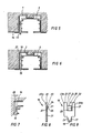
- the mounting bracket shown in more detail in Figures 5 to 9 is inserted into the space 30.
- the mounting bracket 15 is hereby inserted from below into the space 30 in the direction of the arrow 14, FIG. 5 showing the insertion position and FIG. 6 the final state.
- a latching body 21 arranged on the center leg 20 snaps onto an associated, horizontal shoulder 16 of the running rail 6.
- FIGS. 6 and 7 do not show that, in the fully inserted state, the abutment surfaces 22 arranged on the outer legs 23a, 23b strike the underside of the horizontal part of the support profile 1. This limits the insertion of the mounting bracket 15 in the direction of arrow 14.
- the mounting bracket consists of a simple plastic injection molded part, e.g. made of polyamide, and has a fork-like upper part with three, mutually spaced, mutually parallel legs 20,23a 23b.
- the two outer legs 23a, 23b are designed to be longer in the vertical longitudinal extent of the mounting bracket 15 than the center leg 20 arranged therebetween.
- the center leg 20 has at its upper, free end a latching body 21 which, in the unloaded state, extends over the lateral outline of the mounting bracket 15 protrudes.
- the material thickness of the center leg is chosen to be less than the material thickness of the side legs 23a, in order to ensure that the center leg 20 can spring backwards by the difference 28 when the mounting bracket 15 is inserted in the direction of the arrow 14 according to FIG. 5.
- the spring action of the center leg 20 is achieved in that a cross-section-weakening incision 27 is arranged in the foot region.
- two wedge surfaces 24, 25 enclosing an obtuse angle to one another are arranged, each of which is chamfered in the insertion and extension directions of the mounting bracket.
- the center leg 20 is machined out of the material of the mounting bracket by vertical incisions 27.
- the part of the mounting bracket 15 arranged at the bottom in the insertion direction 14 is designed as an elongated tongue 17 of reduced width, on the side surfaces of which ribs 26 are formed.
- the opposing ribs 26 are clamped between the jaws of flat-nose pliers and with the aid of the flat-nose pliers, the mounting bracket can then be pulled out of the space 30 between the support profile 1 and the running rail 6 in the opposite direction to the arrow direction 14 shown.
- a long Licher incision 18 is arranged, in which a tool blade is inserted.
- the mounting bracket 15 is then pushed in by pressing on the tool blade.
Landscapes
- Curtains And Furnishings For Windows Or Doors (AREA)
- Fittings On The Vehicle Exterior For Carrying Loads, And Devices For Holding Or Mounting Articles (AREA)
- Lift-Guide Devices, And Elevator Ropes And Cables (AREA)
- Clamps And Clips (AREA)
- Connection Of Plates (AREA)
Priority Applications (1)
| Application Number | Priority Date | Filing Date | Title |
|---|---|---|---|
| AT84108121T ATE37480T1 (de) | 1983-07-27 | 1984-07-11 | Befestigung einer laufschiene in einem mit der decke verbundenen tragprofil. |
Applications Claiming Priority (2)
| Application Number | Priority Date | Filing Date | Title |
|---|---|---|---|
| DE3327024 | 1983-07-27 | ||
| DE3327024A DE3327024C2 (de) | 1983-07-27 | 1983-07-27 | Befestigung einer Laufschiene in einem mit der Decke verbundenen Tragprofil |
Publications (3)
| Publication Number | Publication Date |
|---|---|
| EP0133230A2 true EP0133230A2 (fr) | 1985-02-20 |
| EP0133230A3 EP0133230A3 (en) | 1985-04-17 |
| EP0133230B1 EP0133230B1 (fr) | 1988-09-28 |
Family
ID=6205021
Family Applications (1)
| Application Number | Title | Priority Date | Filing Date |
|---|---|---|---|
| EP84108121A Expired EP0133230B1 (fr) | 1983-07-27 | 1984-07-11 | Fixation d'une glissière à un profilé de support fixé à un plafond |
Country Status (3)
| Country | Link |
|---|---|
| EP (1) | EP0133230B1 (fr) |
| AT (1) | ATE37480T1 (fr) |
| DE (2) | DE3327024C2 (fr) |
Families Citing this family (1)
| Publication number | Priority date | Publication date | Assignee | Title |
|---|---|---|---|---|
| US11457761B2 (en) * | 2020-07-14 | 2022-10-04 | Blindspace Ab | Drapery system and a method for mounting a drapery track |
Family Cites Families (13)
| Publication number | Priority date | Publication date | Assignee | Title |
|---|---|---|---|---|
| DE1050515B (fr) * | 1959-02-12 | |||
| DE7343410U (de) * | 1974-03-28 | Eurosett Paulick Kg | Kunststoffblende | |
| US1884414A (en) * | 1931-01-21 | 1932-10-25 | H L Judd Company Inc | Bracket for curtain rods |
| DE1978784U (de) * | 1967-04-22 | 1968-02-15 | Ehage Jalousiefabrik Erich Hin | Verschalungskern zur herstellung von zur aufnahme von jalousien bestimmten betonstuerzen. |
| DE2222017C3 (de) * | 1972-05-05 | 1975-02-06 | Walter 8500 Nuernberg Huebner | Vorhangschiene |
| FR2235664A1 (en) * | 1973-07-04 | 1975-01-31 | Boulet Guy | Inverted channel section curtain rail - sections are joined by dowels in sockets on exterior surfaces |
| DE2435301C2 (de) * | 1974-07-23 | 1985-01-10 | Riloga-Werk Julius Schmidt, 5630 Remscheid | Tragschiene für Unterdecken |
| CH597811A5 (en) * | 1974-10-11 | 1978-04-14 | Hanspeter Berger | Curtain rail with spring clip fixing |
| FR2300528A1 (fr) * | 1975-02-13 | 1976-09-10 | Saade & Cie Ets | Support de tringle a rideau |
| FR2425218A1 (fr) * | 1978-05-12 | 1979-12-07 | Boulet Freres & Cie | Support de tringles a rideaux rectangulaires |
| EP0019427B1 (fr) * | 1979-05-12 | 1984-02-01 | Reddiplex Limited | Profilé composite pour châssis de fenêtres et analogues |
| DE3003227A1 (de) * | 1980-01-30 | 1981-08-06 | Suntec Sonnenschutztechnik Gmbh, 2850 Bremerhaven | Halter fuer die befestigung von tragschienen |
| US4411401A (en) * | 1981-02-23 | 1983-10-25 | Hunter Douglas, Inc. | Headrail mounting bracket |
-
1983
- 1983-07-27 DE DE3327024A patent/DE3327024C2/de not_active Expired
-
1984
- 1984-07-11 EP EP84108121A patent/EP0133230B1/fr not_active Expired
- 1984-07-11 DE DE8484108121T patent/DE3474254D1/de not_active Expired
- 1984-07-11 AT AT84108121T patent/ATE37480T1/de not_active IP Right Cessation
Also Published As
| Publication number | Publication date |
|---|---|
| EP0133230A3 (en) | 1985-04-17 |
| EP0133230B1 (fr) | 1988-09-28 |
| ATE37480T1 (de) | 1988-10-15 |
| DE3474254D1 (en) | 1988-11-03 |
| DE3327024C2 (de) | 1985-10-24 |
| DE3327024A1 (de) | 1985-02-14 |
Similar Documents
| Publication | Publication Date | Title |
|---|---|---|
| DE69014966T2 (de) | Versteifungsvorrichtung für Kabelkanäle oder Kabelwege und entsprechende Verklammerungen. | |
| WO2018028842A1 (fr) | Dispositif de fixation d'un objet de préférence plat sur une construction | |
| EP3585210B1 (fr) | Tiroir et procédé de montage d'un tiroir | |
| DE1509900C3 (de) | Halterung für eine Scheibe oder Füllungsplatte in einem Fensterrahmen, Türrahmen od.dgl | |
| AT503229A1 (de) | Vorrichtung zum befestigen eines abdeckprofils für den übergang zwischen zwei zueinander senkrechten flächen | |
| DE2005611C3 (de) | Lösbare Verbindung zweier Profilstabe mit U-förmigem Querschnitt | |
| EP0133230B1 (fr) | Fixation d'une glissière à un profilé de support fixé à un plafond | |
| DE3317208C2 (de) | Wandelement zur Auskleidung und Aufteilung eines mindestens eine Deckenfläche und Bodenfläche aufweisenden Raumes | |
| DE10338158A1 (de) | Haltevorrichtung für einen Einschub | |
| DE1040760B (de) | Laufschiene aus Kunststoff fuer Vorhaenge, Gardinen od. dgl. | |
| DE19531658B4 (de) | Stützvorrichtung für eine Kabelbahn | |
| DE3020951C2 (de) | Vorrichtung zum Befestigen eines Schildes an einem Pfosten | |
| EP1491698B1 (fr) | Revêtement constitué de barres pour des plafonds, murs ou des éléments de construction similaires | |
| EP2803779A1 (fr) | Système de fixation d'un rail | |
| AT401951B (de) | Montageschiene | |
| DE102007060953A1 (de) | Rastvorrichtung | |
| DE3905896A1 (de) | Klammer zur halterung von verkleidungsplatten an fassadenwaenden | |
| DE3542434A1 (de) | Befestigung einer profilstange an einer basis, insbesondere fuer elektrische schalt- und/oder verteileranlagen | |
| DE19860743C1 (de) | Wandhalter für Verkleidungstafeln, insbesondere Fassadenelemente | |
| DE29622162U1 (de) | Mehrzweck-Abhänger für C-Profilschienen | |
| DE29717928U1 (de) | Befestigungssystem zur Montage von Decken- und Wandverkleidungen | |
| DE4421107A1 (de) | Vorrichtung zur Verbindung von Profilleisten | |
| DE3911843C2 (fr) | ||
| DE29600514U1 (de) | Traggitter für abgehängte Decken mit sich kreuzenden langgestreckten T-Profil-Längsschienen und -Querschienen und Abhänger zum Befestigen der Querschienen an den Längsschienen | |
| DE8617604U1 (de) | Schubkasten |
Legal Events
| Date | Code | Title | Description |
|---|---|---|---|
| PUAI | Public reference made under article 153(3) epc to a published international application that has entered the european phase |
Free format text: ORIGINAL CODE: 0009012 |
|
| PUAL | Search report despatched |
Free format text: ORIGINAL CODE: 0009013 |
|
| AK | Designated contracting states |
Designated state(s): AT BE CH DE FR GB IT LI LU NL SE |
|
| AK | Designated contracting states |
Designated state(s): AT BE CH DE FR GB IT LI LU NL SE |
|
| 17P | Request for examination filed |
Effective date: 19850925 |
|
| 17Q | First examination report despatched |
Effective date: 19860908 |
|
| D17Q | First examination report despatched (deleted) | ||
| GRAA | (expected) grant |
Free format text: ORIGINAL CODE: 0009210 |
|
| AK | Designated contracting states |
Kind code of ref document: B1 Designated state(s): AT BE CH DE FR GB IT LI LU NL SE |
|
| PG25 | Lapsed in a contracting state [announced via postgrant information from national office to epo] |
Ref country code: SE Effective date: 19880928 Ref country code: NL Effective date: 19880928 Ref country code: IT Free format text: LAPSE BECAUSE OF FAILURE TO SUBMIT A TRANSLATION OF THE DESCRIPTION OR TO PAY THE FEE WITHIN THE PRESCRIBED TIME-LIMIT;WARNING: LAPSES OF ITALIAN PATENTS WITH EFFECTIVE DATE BEFORE 2007 MAY HAVE OCCURRED AT ANY TIME BEFORE 2007. THE CORRECT EFFECTIVE DATE MAY BE DIFFERENT FROM THE ONE RECORDED. Effective date: 19880928 Ref country code: GB Free format text: LAPSE BECAUSE OF NON-PAYMENT OF DUE FEES Effective date: 19880928 Ref country code: FR Free format text: THE PATENT HAS BEEN ANNULLED BY A DECISION OF A NATIONAL AUTHORITY Effective date: 19880928 Ref country code: BE Effective date: 19880928 |
|
| REF | Corresponds to: |
Ref document number: 37480 Country of ref document: AT Date of ref document: 19881015 Kind code of ref document: T |
|
| REF | Corresponds to: |
Ref document number: 3474254 Country of ref document: DE Date of ref document: 19881103 |
|
| EN | Fr: translation not filed | ||
| NLV1 | Nl: lapsed or annulled due to failure to fulfill the requirements of art. 29p and 29m of the patents act | ||
| GBV | Gb: ep patent (uk) treated as always having been void in accordance with gb section 77(7)/1977 [no translation filed] | ||
| PG25 | Lapsed in a contracting state [announced via postgrant information from national office to epo] |
Ref country code: AT Effective date: 19890711 |
|
| PLBE | No opposition filed within time limit |
Free format text: ORIGINAL CODE: 0009261 |
|
| STAA | Information on the status of an ep patent application or granted ep patent |
Free format text: STATUS: NO OPPOSITION FILED WITHIN TIME LIMIT |
|
| PG25 | Lapsed in a contracting state [announced via postgrant information from national office to epo] |
Ref country code: LU Free format text: LAPSE BECAUSE OF NON-PAYMENT OF DUE FEES Effective date: 19890731 |
|
| 26N | No opposition filed | ||
| PGFP | Annual fee paid to national office [announced via postgrant information from national office to epo] |
Ref country code: CH Payment date: 19890927 Year of fee payment: 6 |
|
| PG25 | Lapsed in a contracting state [announced via postgrant information from national office to epo] |
Ref country code: LI Effective date: 19900731 Ref country code: CH Effective date: 19900731 |
|
| REG | Reference to a national code |
Ref country code: CH Ref legal event code: PL |
|
| PGFP | Annual fee paid to national office [announced via postgrant information from national office to epo] |
Ref country code: DE Payment date: 19940721 Year of fee payment: 11 |
|
| PG25 | Lapsed in a contracting state [announced via postgrant information from national office to epo] |
Ref country code: DE Effective date: 19960402 |