EP0133293A2 - Emballage comportant deux matériaux différents - Google Patents
Emballage comportant deux matériaux différents Download PDFInfo
- Publication number
- EP0133293A2 EP0133293A2 EP84108855A EP84108855A EP0133293A2 EP 0133293 A2 EP0133293 A2 EP 0133293A2 EP 84108855 A EP84108855 A EP 84108855A EP 84108855 A EP84108855 A EP 84108855A EP 0133293 A2 EP0133293 A2 EP 0133293A2
- Authority
- EP
- European Patent Office
- Prior art keywords
- cup
- collar
- wall
- component
- neck
- Prior art date
- Legal status (The legal status is an assumption and is not a legal conclusion. Google has not performed a legal analysis and makes no representation as to the accuracy of the status listed.)
- Granted
Links
Images


Classifications
-
- B—PERFORMING OPERATIONS; TRANSPORTING
- B65—CONVEYING; PACKING; STORING; HANDLING THIN OR FILAMENTARY MATERIAL
- B65D—CONTAINERS FOR STORAGE OR TRANSPORT OF ARTICLES OR MATERIALS, e.g. BAGS, BARRELS, BOTTLES, BOXES, CANS, CARTONS, CRATES, DRUMS, JARS, TANKS, HOPPERS, FORWARDING CONTAINERS; ACCESSORIES, CLOSURES, OR FITTINGS THEREFOR; PACKAGING ELEMENTS; PACKAGES
- B65D51/00—Closures not otherwise provided for
- B65D51/24—Closures not otherwise provided for combined or co-operating with auxiliary devices for non-closing purposes
- B65D51/28—Closures not otherwise provided for combined or co-operating with auxiliary devices for non-closing purposes with auxiliary containers for additional articles or materials
- B65D51/2807—Closures not otherwise provided for combined or co-operating with auxiliary devices for non-closing purposes with auxiliary containers for additional articles or materials the closure presenting means for placing the additional articles or materials in contact with the main contents by acting on a part of the closure without removing the closure, e.g. by pushing down, pulling up, rotating or turning a part of the closure, or upon initial opening of the container
- B65D51/2814—Closures not otherwise provided for combined or co-operating with auxiliary devices for non-closing purposes with auxiliary containers for additional articles or materials the closure presenting means for placing the additional articles or materials in contact with the main contents by acting on a part of the closure without removing the closure, e.g. by pushing down, pulling up, rotating or turning a part of the closure, or upon initial opening of the container the additional article or materials being released by piercing, cutting or tearing an element enclosing it
- B65D51/2842—Closures not otherwise provided for combined or co-operating with auxiliary devices for non-closing purposes with auxiliary containers for additional articles or materials the closure presenting means for placing the additional articles or materials in contact with the main contents by acting on a part of the closure without removing the closure, e.g. by pushing down, pulling up, rotating or turning a part of the closure, or upon initial opening of the container the additional article or materials being released by piercing, cutting or tearing an element enclosing it said element being provided with a preformed weakened line
Definitions
- the invention relates to a two-component pack with a cup arranged in the pack neck for receiving the one component and a screw cap assigned to the pack neck with a collar protruding into the cup, the end edge of which forms a butt edge for separating the cup in the area of a predetermined breaking line by another Unscrew the screw cap beyond the basic sales position.
- a two-component pack of this type is known from GB-PS 1 083 335.
- the cylindrical collar formed centrally on the screw cap cover and the base of the cup extending in front of it form the actual receiving chamber of the one component.
- the predetermined breaking line lies in the bottom edge zone. In the basic sales position, the front edge lies there.
- the one component is powdery material.
- the sealing relationships between the cup and the collar take this into account accordingly.
- Such a package is therefore less suitable for liquid components; For example, due to the capillary action in the joint between the cup and neck, a not inconsiderable proportion of the mixture would be removed.
- a similar two-component pack is known from GB-PS 15 57 521, but which has no screw cap.
- the separation of the cup is effected by the rotary movement of the cap and the lower part is practically stalled.
- relatively complicated means have to be used, namely primarily a special design of the bottle neck.
- the bottle neck forms axially lying ribs on the inside.
- the distance between the individual ribs leads to engagement grooves for cup-like, strip-like projections.
- the latter sit on the lower, detachable part of the cup.
- This detachable part is held against rotation by the meshing of the ribs or strips.
- the upper part of the cup is in rotational engagement with the clipped-on cap. Similar coupling agents are used for this.
- This configuration is complicated and expensive to manufacture.
- the cup is bound to very specific container shapes (which have the necessary countermeasures in the neck).
- a two-component pack of particularly high utility value is achieved: because the predetermined breaking line is now provided at a distance from the cup bottom, the collar no longer exerts a compressive effect like a piston; rather, the collar only runs a short distance inside the cup.
- This has significant advantages, especially for automatic filling. Since the predetermined breaking point is formed by a ring step of the cup jacket wall lying in the cup, the best conditions result for the separation of the cup. The corresponding forces of the collar act directly on the ring step from above, i.e. in the most stable plane of the cup.
- the abutting edge of the collar is approximately flush with the ring step of the cup wall.
- the upper section of the cup which is wider in cross section, serves as a guide surface for the collar. This means that there can be no different loads in the area of the predetermined breaking line.
- the cup itself is held securely in the neck. It is also advantageous that the cup is conical at least below the ring step.
- the ring step is located approximately at half the height of the cup, this results in advantageous stackability of the cups. This is particularly favorable for magazine storage, of course also for warehousing and Shipping.
- a safe fixing of the cup also results from the fact that the cup wall is tied in the pack neck via a clip step located near the mouth of the packing neck and the outer surface of the cup wall runs below the clip step at a distance from the inner surface of the pack neck. The distance there provides advantageous radial flexibility, which benefits the seal between the collar and the cup.
- the position of the clip step that is as close as possible to the mouth brings the advantageous effect of the tight closure only at the last moment of the cup assignment.
- the screw cap itself is also held in clips on the pack.
- the procedure is such that the screw cap locks behind a clip shoulder of the neck in the basic sales position and the lowest area of the screw thread is composed of individual threaded cams lying one behind the other in the circumferential direction with an interruption.
- This interrupted pre-thread allows the cap to be simply pressed on, the thread cams being skipped by the internal thread of the screw cap, until the clip point is reached.
- the one-sided flank support of the thread given by the pre-thread favors the tilt-free screwing on of the cap.
- the cams are advantageously lenticular and of different heights. This measure also favors the bouncing of the screw cap. In the basic sales position reached, the butt edge of the collar is still at a distance from the ring step.
- the clip step and the clip shoulder are arranged approximately on the same cross-sectional plane.
- the material that is displaced outwards can be used to form the clip shoulder (simple material shift).
- the ring step by a bridge between two in the radial Sections of the cup jacket wall lying offset from one another are formed.
- the corresponding jacket wall offset can easily be generated by injection molding.
- an offset dimension is advantageously used, which corresponds approximately to the thickness of the jacket wall.
- the height of the offset edges one of which represents the ring step on the inside of the cup, determines the tear resistance of the material bridge.
- the invention further proposes that the bead of the cup wall be gripped behind by a clip shoulder of the collar.
- the closing path does not have to be covered again to release the filling contents; rather, the predetermined breaking point is destroyed when the cap is completely screwed on to the larger-volume packaging.
- the cup wall on its outer surface, adjacent to the cup-bottom section forms a support wall which arises from the section lying in front of the predetermined breaking point and extends to the level of the cup bottom underside .
- Such a support wall acts as a spacer and keeps the detachable portion of the cup free from assembly loads.
- the supporting wall can advantageously be formed by a closed ring collar, as a result of which the closing loading forces are distributed over the entire cross-sectional wall cross section.
- the jacket wall of the cup wall carries spacer ribs. The latter provide a balanced support in the bottle neck, but on the other hand stabilize the cup itself in an advantageous manner.
- the edge of the cup forms an upwardly open annular groove. The edge becomes relatively flexible, which helps to achieve the tightly fitting seat.
- an advantageous embodiment is the same as several in the height direction other beads on the cup wall are reached. Such beads define, for example, different interlocking depths, with each securing of the inserted plug position. They also let air escape when skipping.
- the two-component pack holds one component I in a cup 2 inserted into the pack neck 1 and the other component 11 in the larger-volume pack 3.
- a screw cap 4 designed as a closure serves as a separating tool.
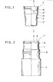
- the cup 2 which is made of plastic, forms an outwardly directed edge 5 in its upper, essentially cylindrical section. This overlaps the corresponding end edge 1 'of the packing neck 1.
- the edge 5 does not protrude outwards and defines the hanging depth of the cup 2.
- the latter is, however, additionally secured against falling out.
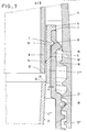
- the cup wall W is tied in the pack neck via a clip step St located near the mouth 6 of the pack neck 1.
- This clip level is realized by an annular rib 7 on the outer surface of the cup jacket wall W, which annular rib 7 engages in a shape-matching annular groove 8 on the inner surface of the packing neck 1.
- the outer surface of the cup jacket wall W runs below the clip step St at a distance x from the inner surface of the packing neck 1 (see FIG. 7). This allows the cup 2 to be inserted easily.
- the sealing assignment arises only at the last moment of the insertion assignment, with friction occurring between the annular rib 7 and the cylindrical inner surface of the packing neck 1. Due to the proximity to the mouth 6, this zone of increased friction is considerably reduced; there is also no significant compression in the interior of the pack when assigning the cups. Even a little compression would not be able to push the cup out again. The clip forces are adjusted accordingly.
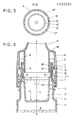
- the latter is formed by an annular step A of the cup jacket wall W lying in the cup and at a distance y from the cup base 2 ".
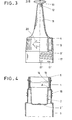
- the abutting edge 9 'of a collar 9 of the screw cap 4 which enters the cup from above meets the latter.
- the latter is rooted in the screw cap cover 10 and is designed as a cylindrical ring wall, the abutting edge extends perpendicular to the longitudinal center axis zz of the rotationally symmetrical two-component pack.
- the collar 9 continues upwards into a muzzle tube 11 which tapers continuously towards the free end. Its mouth opening 12 is kept closed by a molded plug 13. It is a tamper-evident seal.
- the abutting edge 9 'of the collar 9 is essentially flush with the ring step A of the cup jacket wall W.
- the distance dimension y corresponds to approximately 2/3 of the height of the cup 2.
- the outer surface of the collar 9 is sealed to the inner surface of the cup wall in the basic sales position by a bead 14 located near the collar edge 9 '.
- the bead 14 is as close as possible to the abutting edge 9 ', so that here, too, when the screw cap is assigned, the friction and sealing are only present at the last moment, so that the screw cap 4 cannot be braced against the internal pressure which forms. There is also a safety precaution. The latter is that the screw cap 4 locks in the basic sales position behind a clip shoulder 15 of the packing neck 1.
- the clip shoulder 15 extends approximately on the same cross-sectional plane as the clip step St.
- the shoulder-forming wall section consists practically or in part of the displacement material of the annular groove 8.
- the counter-shoulder 16 on the screw cap side is an annular rib directed towards the cap.
- the lens shape brings both in the direction of rotation of the screw cap 4 and in the transverse direction of the same (cap attachment direction) convex curves.
- the distance between them corresponds approximately to a cam length.
- a total of 8 cams extend over the circumference. They have different heights, so that the transfer of the external thread 18 is facilitated when bouncing or screwing on. For screwing on there is the advantage of a tilt-free assignment of the screw cap 4.
- the offset of the wall sections 2 "and 2" 'to each other corresponds to slightly more than the thickness of the cup jacket wall W. Both jacket wall sections overlap one another in the area of the material bridge 21. The degree of overlap corresponds to approximately one fifth of the thickness of the jacket wall. Below the ring step A, the cup 2 is frustoconical.
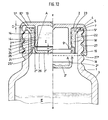
- the two-component pack according to the second embodiment is basically of the same structure; the reference numerals are, insofar as is necessary for understanding, correspondingly entered in FIGS. 10 to 12.
- the lateral surface of the cup wall W has spacing ribs 22 which extend in the insertion direction of the cup 2 and which clamp against the inner wall of the packing neck 1 and thus provide good rotational security.
- spacer ribs 22 stiffen the cup wall W.
- the rib width corresponds to the intermediate rib-free zone.
- the spacing ribs 22 run into a diverging edge section 5 ', forming a frustoconical contact surface, which dips sealingly into the neck 1 and, due to an upwardly open annular groove 23, is particularly elastic.
- the annular groove is, seen in cross-section, notch-valley-shaped with an obliquely outward flank and a steep, i.e. H. Flank running concentrically to the longitudinal center axis z-z of the rotationally symmetrical two-component pack.
- the butt edge 9 ′ which is essentially aligned with the ring step A of the cup wall W, extends in the area on the left in FIG. 12 benen position at a closer distance to the ring step A than in Fig. 6, so that therefore a flatter small package is achieved.
- the cup wall W forms at least one annular bead 14 on the inside.
- the latter extends horizontally in the vicinity of the ring step A and is engaged behind by an annular clip shoulder 24 formed onto the outer surface of the collar 9.
- This clip shoulder located at a short distance from the free end of the collar 9, is resilient when the cup and screw cap are connected.
- three beads 14 of the cup wall lying one above the other in the vertical direction are formed on the inside. The distance between the beads 14 corresponds approximately to twice the width of a bead, which beads also provide a good seal in addition to the axial fixing of the parts forming a capsule.
- the screw cap according to FIG. 11 is placed on the back.
- the upwardly facing collar 9 thus forms a cup-like filling space on the inside.
- the cup is then assigned with the cup opening facing downwards.
- the clip shoulder 24 successively overflows one or more beads 14 defining the insertion depth.
- the cup wall W In order to keep away any impairment from the bottom-side section 2 "connected to the upper section 2"'of the cup via the predetermined breaking line during this assembly, the cup wall W, adjacent to the cup-bottom side section 2 ", continues into a support wall 25.
- the support wall arises from the area of the predetermined breaking point and is advanced to the level of the bottom side of the bottom of the cup 26.
- the end face 25 ' can even protrude slightly from the bottom of the bottom 26 of the cup does not come to the bottom of the cup bottom 26 even with a slight axial compression of the casing wall.
- a further protective cover can also be used, namely the essentially cylindrical cup wall 27 of the screw cap 4 by the End face 25 'of the support wall 25 is brought into alignment, ie level with the end wall 27' of the cap wall 27. With this full immersion position, the small annular gap between the abutting edge 9 'of the collar 9 is retained. In addition, there remains a distance D between the top 5 ′′ of the collar 9 and the corresponding inner surface 10 ′ of the screw cap cover 10.
- the spacer ribs 22 terminate at the same height as the end face 25 ', so that the contact surface is enlarged by the end faces of the spacer ribs.
- the capsule of the larger-volume, for example water-containing package 3 is also assigned here under the threaded engagement 16/18 of screw cap 4 and bottle neck 1.
- the thread engagement between the screw cap 4 and the packing neck is of such a length that the lower section 2 "of the cup 2 is cut off while screwing on, whereas the upper section 2 "'remains in the bottle neck.
- the film hinge-like material bridge 21 is torn between the two sections 2 "and 2" 'of the cup wall W which are offset from one another in the radial direction.
- the separated cup section 2 "falls into the package 3. Both components can now be mixed well by shaking.
- the detached container section 2" also serves as a shaking mixing body. The tight seal between the collar and the cup wall is maintained during shaking.
- the mixed substance can be dispensed.
Landscapes
- Engineering & Computer Science (AREA)
- Mechanical Engineering (AREA)
- Closures For Containers (AREA)
Priority Applications (1)
| Application Number | Priority Date | Filing Date | Title |
|---|---|---|---|
| AT84108855T ATE25225T1 (de) | 1983-07-30 | 1984-07-26 | Zwei-komponenten-packung. |
Applications Claiming Priority (4)
| Application Number | Priority Date | Filing Date | Title |
|---|---|---|---|
| DE3327615 | 1983-07-30 | ||
| DE3327615A DE3327615C2 (de) | 1983-07-30 | 1983-07-30 | Zwei-Komponenten-Packung |
| DE19843426739 DE3426739A1 (de) | 1984-07-20 | 1984-07-20 | Zwei-komponenten-packung |
| DE3426739 | 1984-07-20 |
Publications (3)
| Publication Number | Publication Date |
|---|---|
| EP0133293A2 true EP0133293A2 (fr) | 1985-02-20 |
| EP0133293A3 EP0133293A3 (en) | 1986-01-15 |
| EP0133293B1 EP0133293B1 (fr) | 1987-01-28 |
Family
ID=25812773
Family Applications (1)
| Application Number | Title | Priority Date | Filing Date |
|---|---|---|---|
| EP84108855A Expired EP0133293B1 (fr) | 1983-07-30 | 1984-07-26 | Emballage comportant deux matériaux différents |
Country Status (2)
| Country | Link |
|---|---|
| EP (1) | EP0133293B1 (fr) |
| DE (1) | DE3462237D1 (fr) |
Cited By (11)
| Publication number | Priority date | Publication date | Assignee | Title |
|---|---|---|---|---|
| FR2568547A1 (fr) * | 1984-08-04 | 1986-02-07 | Celamerck Gmbh & Co Kg | Dispositif de melange et de pulverisation de substances concentrees et utilisation de ce dispositif |
| EP0237889A3 (en) * | 1986-03-13 | 1988-09-21 | Robert Finke Kommanditgesellschaft | Two-component package |
| FR2623477A1 (fr) * | 1987-11-20 | 1989-05-26 | Sah Participations Proced Indl | Bouchon comportant un godet de matiere absorbante fixe de facon definitive au bouchon |
| WO1991017930A3 (fr) * | 1990-05-21 | 1992-01-09 | Finke Robert Gmbh | Emballage a plusieurs constituants |
| FR2736038A1 (fr) * | 1995-06-28 | 1997-01-03 | Inibsa Lab | Flacon pour deux produits |
| EP0921079A1 (fr) | 1997-12-02 | 1999-06-09 | Plastikwerk Expan GesmbH | Récipient à deux compartiments |
| EP0943552A1 (fr) * | 1998-03-20 | 1999-09-22 | Wella Aktiengesellschaft | Récipient pour emballer un premier et un second matériaux maintenus séparés avant d'être utilisés mélangés |
| WO2001076977A1 (fr) * | 2000-04-12 | 2001-10-18 | Emvi Limited | Reservoir servant a melanger deux contenus |
| AT410085B (de) * | 1997-12-02 | 2003-01-27 | Feichtinger Ernst Expan | Behälter |
| WO2006004345A1 (fr) * | 2004-07-01 | 2006-01-12 | Hyo Bin Im | Ensemble de couvercle pour le melange de matiere interne au niveau d'une ouverture |
| FR2916187A1 (fr) * | 2007-05-14 | 2008-11-21 | Marguerite Deperrois | Bouchon pour recipient formant reservoir d'additif |
Family Cites Families (5)
| Publication number | Priority date | Publication date | Assignee | Title |
|---|---|---|---|---|
| GB1083335A (en) * | 1963-05-28 | 1967-09-13 | Calmic Ltd | Storing, mixing and dispensing devices,e.g. for antibiotics |
| US3458076A (en) * | 1968-06-26 | 1969-07-29 | Owens Illinois Inc | Two-compartment package |
| FR2169445A6 (fr) * | 1971-03-15 | 1973-09-07 | Oreal | |
| FR2153767A5 (fr) * | 1971-09-23 | 1973-05-04 | Gallia Sa Eugene | |
| FR2370650A1 (fr) * | 1976-11-15 | 1978-06-09 | Oreal | Recipient de conditionnement et de distribution comportant au stockage deux compartiments separes |
-
1984
- 1984-07-26 EP EP84108855A patent/EP0133293B1/fr not_active Expired
- 1984-07-26 DE DE8484108855T patent/DE3462237D1/de not_active Expired
Cited By (18)
| Publication number | Priority date | Publication date | Assignee | Title |
|---|---|---|---|---|
| FR2568547A1 (fr) * | 1984-08-04 | 1986-02-07 | Celamerck Gmbh & Co Kg | Dispositif de melange et de pulverisation de substances concentrees et utilisation de ce dispositif |
| EP0170980A3 (en) * | 1984-08-04 | 1987-11-11 | Celamerck Gmbh & Co. Kg | Mixing and spraying device |
| EP0237889A3 (en) * | 1986-03-13 | 1988-09-21 | Robert Finke Kommanditgesellschaft | Two-component package |
| FR2623477A1 (fr) * | 1987-11-20 | 1989-05-26 | Sah Participations Proced Indl | Bouchon comportant un godet de matiere absorbante fixe de facon definitive au bouchon |
| WO1991017930A3 (fr) * | 1990-05-21 | 1992-01-09 | Finke Robert Gmbh | Emballage a plusieurs constituants |
| EP0462390A3 (en) * | 1990-05-21 | 1992-05-13 | Robert Finke Gmbh & Co. Kg | Multicomponent package |
| US5353928A (en) * | 1990-05-21 | 1994-10-11 | Robert Finke Gmbh & Co. Kg | Multicomponent package |
| BE1010542A5 (fr) * | 1995-06-28 | 1998-10-06 | Inibsa Lab | Nouveau flacon pour deux produits. |
| FR2736038A1 (fr) * | 1995-06-28 | 1997-01-03 | Inibsa Lab | Flacon pour deux produits |
| EP0921079A1 (fr) | 1997-12-02 | 1999-06-09 | Plastikwerk Expan GesmbH | Récipient à deux compartiments |
| US6073803A (en) * | 1997-12-02 | 2000-06-13 | Plastikwerk Expan Gmbh | Container |
| AT410085B (de) * | 1997-12-02 | 2003-01-27 | Feichtinger Ernst Expan | Behälter |
| EP0943552A1 (fr) * | 1998-03-20 | 1999-09-22 | Wella Aktiengesellschaft | Récipient pour emballer un premier et un second matériaux maintenus séparés avant d'être utilisés mélangés |
| WO2001076977A1 (fr) * | 2000-04-12 | 2001-10-18 | Emvi Limited | Reservoir servant a melanger deux contenus |
| WO2006004345A1 (fr) * | 2004-07-01 | 2006-01-12 | Hyo Bin Im | Ensemble de couvercle pour le melange de matiere interne au niveau d'une ouverture |
| US7578386B2 (en) | 2004-07-01 | 2009-08-25 | Hyo Bin Im | Cover assembly enable to mix interior material at opening |
| FR2916187A1 (fr) * | 2007-05-14 | 2008-11-21 | Marguerite Deperrois | Bouchon pour recipient formant reservoir d'additif |
| WO2008152219A1 (fr) * | 2007-05-14 | 2008-12-18 | Marguerite Deperrois | Bouchon pour recipient formant reservoir d'additif |
Also Published As
| Publication number | Publication date |
|---|---|
| DE3462237D1 (en) | 1987-03-05 |
| EP0133293B1 (fr) | 1987-01-28 |
| EP0133293A3 (en) | 1986-01-15 |
Similar Documents
| Publication | Publication Date | Title |
|---|---|---|
| DE3327615C2 (de) | Zwei-Komponenten-Packung | |
| DE2753737C2 (de) | Behälter für zwei schüttbare Stoffe | |
| DE60216215T2 (de) | Kindersicherheitsverschluss und Verpackung | |
| DE2529340C3 (de) | Behälter mit einer Schraubkappe und Verfahren zum Aufsetzen der Schraubkappe | |
| DE69303434T2 (de) | Behälter für pharmazeutische Produkte aus zwei gesonderten Komponenten, mit Mitteln zu deren Mischung und dosierter Ausgabe | |
| EP0235806B1 (fr) | Capsule d'étanchéité de bouteille pour récipients contenant deux composants | |
| EP0431347B1 (fr) | Fermeture pour cartouche de distribution | |
| EP0520207A1 (fr) | Fermeture pour bouteilles de produits à deux composants | |
| DE8814309U1 (de) | Mischvorrichtung | |
| EP0133293B1 (fr) | Emballage comportant deux matériaux différents | |
| DE69404505T2 (de) | Auslass-Verschluss | |
| EP0243730A2 (fr) | Flacon à deux compartiments | |
| AT394536B (de) | Zweiteilige verschlusskappe mit schraubgewinde | |
| DE8606940U1 (de) | Zwei-Komponenten-Packung | |
| DE19807768A1 (de) | Kunststoffdeckel mit Kunststoffverschluß | |
| DE3517072A1 (de) | Dosiervorrichtung fuer fluessigkeiten | |
| DE2625175C3 (de) | Behälter-Verschluß mit Wirkstoff kammer | |
| WO1998045189A1 (fr) | Element soude verseur en plastique | |
| EP0184742B1 (fr) | Distributeur pour la décharge en portion unique de pastilles, pâtes ou similaires | |
| DE3437574C2 (fr) | ||
| DE69603290T2 (de) | Zweiteilige spenderkappe mit garantieverschluss | |
| DE8710784U1 (de) | Flasche mit Kappe | |
| EP1465814A2 (fr) | Dispositif de fermeture de contenant | |
| WO2003093115A2 (fr) | Bouchon de fermeture pour bouteilles | |
| DE9403102U1 (de) | Kindersicherer Schraubverschluß mit integrierter Nachfüllöffnung |
Legal Events
| Date | Code | Title | Description |
|---|---|---|---|
| PUAI | Public reference made under article 153(3) epc to a published international application that has entered the european phase |
Free format text: ORIGINAL CODE: 0009012 |
|
| AK | Designated contracting states |
Designated state(s): AT BE CH DE FR GB LI LU NL |
|
| PUAL | Search report despatched |
Free format text: ORIGINAL CODE: 0009013 |
|
| AK | Designated contracting states |
Designated state(s): AT BE CH DE FR GB LI LU NL |
|
| 17P | Request for examination filed |
Effective date: 19851231 |
|
| 17Q | First examination report despatched |
Effective date: 19860715 |
|
| GRAA | (expected) grant |
Free format text: ORIGINAL CODE: 0009210 |
|
| AK | Designated contracting states |
Kind code of ref document: B1 Designated state(s): AT BE CH DE FR GB LI LU NL |
|
| REF | Corresponds to: |
Ref document number: 25225 Country of ref document: AT Date of ref document: 19870215 Kind code of ref document: T |
|
| REF | Corresponds to: |
Ref document number: 3462237 Country of ref document: DE Date of ref document: 19870305 |
|
| ET | Fr: translation filed | ||
| PLBI | Opposition filed |
Free format text: ORIGINAL CODE: 0009260 |
|
| 26 | Opposition filed |
Opponent name: L' OREAL Effective date: 19871008 |
|
| NLR1 | Nl: opposition has been filed with the epo |
Opponent name: L' OREAL |
|
| PLBN | Opposition rejected |
Free format text: ORIGINAL CODE: 0009273 |
|
| STAA | Information on the status of an ep patent application or granted ep patent |
Free format text: STATUS: OPPOSITION REJECTED |
|
| 27O | Opposition rejected |
Effective date: 19881021 |
|
| NLR2 | Nl: decision of opposition | ||
| EPTA | Lu: last paid annual fee | ||
| PGFP | Annual fee paid to national office [announced via postgrant information from national office to epo] |
Ref country code: CH Payment date: 20000104 Year of fee payment: 16 |
|
| PGFP | Annual fee paid to national office [announced via postgrant information from national office to epo] |
Ref country code: AT Payment date: 20000113 Year of fee payment: 16 |
|
| PGFP | Annual fee paid to national office [announced via postgrant information from national office to epo] |
Ref country code: NL Payment date: 20000117 Year of fee payment: 16 |
|
| PGFP | Annual fee paid to national office [announced via postgrant information from national office to epo] |
Ref country code: LU Payment date: 20000120 Year of fee payment: 16 |
|
| PGFP | Annual fee paid to national office [announced via postgrant information from national office to epo] |
Ref country code: BE Payment date: 20000208 Year of fee payment: 16 |
|
| PG25 | Lapsed in a contracting state [announced via postgrant information from national office to epo] |
Ref country code: LU Free format text: LAPSE BECAUSE OF NON-PAYMENT OF DUE FEES Effective date: 20000726 Ref country code: AT Free format text: LAPSE BECAUSE OF NON-PAYMENT OF DUE FEES Effective date: 20000726 |
|
| PG25 | Lapsed in a contracting state [announced via postgrant information from national office to epo] |
Ref country code: LI Free format text: LAPSE BECAUSE OF NON-PAYMENT OF DUE FEES Effective date: 20000731 Ref country code: CH Free format text: LAPSE BECAUSE OF NON-PAYMENT OF DUE FEES Effective date: 20000731 Ref country code: BE Free format text: LAPSE BECAUSE OF NON-PAYMENT OF DUE FEES Effective date: 20000731 |
|
| BERE | Be: lapsed |
Owner name: ROBERT FINKE K.G. Effective date: 20000731 |
|
| PG25 | Lapsed in a contracting state [announced via postgrant information from national office to epo] |
Ref country code: NL Free format text: LAPSE BECAUSE OF NON-PAYMENT OF DUE FEES Effective date: 20010201 |
|
| REG | Reference to a national code |
Ref country code: CH Ref legal event code: PL |
|
| NLV4 | Nl: lapsed or anulled due to non-payment of the annual fee |
Effective date: 20010201 |
|
| REG | Reference to a national code |
Ref country code: GB Ref legal event code: IF02 |
|
| PGFP | Annual fee paid to national office [announced via postgrant information from national office to epo] |
Ref country code: FR Payment date: 20030609 Year of fee payment: 20 |
|
| PGFP | Annual fee paid to national office [announced via postgrant information from national office to epo] |
Ref country code: GB Payment date: 20030612 Year of fee payment: 20 |
|
| PGFP | Annual fee paid to national office [announced via postgrant information from national office to epo] |
Ref country code: DE Payment date: 20030625 Year of fee payment: 20 |
|
| PG25 | Lapsed in a contracting state [announced via postgrant information from national office to epo] |
Ref country code: GB Free format text: LAPSE BECAUSE OF EXPIRATION OF PROTECTION Effective date: 20040725 |
|
| REG | Reference to a national code |
Ref country code: GB Ref legal event code: PE20 |