EP0133300A1 - Dispositif stabilisé pour transformer un mouvement rotatif en un mouvement linéaire - Google Patents
Dispositif stabilisé pour transformer un mouvement rotatif en un mouvement linéaire Download PDFInfo
- Publication number
- EP0133300A1 EP0133300A1 EP84108875A EP84108875A EP0133300A1 EP 0133300 A1 EP0133300 A1 EP 0133300A1 EP 84108875 A EP84108875 A EP 84108875A EP 84108875 A EP84108875 A EP 84108875A EP 0133300 A1 EP0133300 A1 EP 0133300A1
- Authority
- EP
- European Patent Office
- Prior art keywords
- nut
- thread
- screw shaft
- primary
- planetary rollers
- Prior art date
- Legal status (The legal status is an assumption and is not a legal conclusion. Google has not performed a legal analysis and makes no representation as to the accuracy of the status listed.)
- Granted
Links
- 230000033001 locomotion Effects 0.000 title claims abstract description 39
- 238000006243 chemical reaction Methods 0.000 claims 2
- 230000002457 bidirectional effect Effects 0.000 description 9
- 230000008859 change Effects 0.000 description 5
- 230000001133 acceleration Effects 0.000 description 3
- 230000007246 mechanism Effects 0.000 description 3
- 238000009795 derivation Methods 0.000 description 2
- 230000000694 effects Effects 0.000 description 2
- 230000006698 induction Effects 0.000 description 2
- 230000013011 mating Effects 0.000 description 2
- 238000000034 method Methods 0.000 description 2
- 238000005096 rolling process Methods 0.000 description 2
- 239000013598 vector Substances 0.000 description 2
- 230000009471 action Effects 0.000 description 1
- 238000010276 construction Methods 0.000 description 1
- 238000005520 cutting process Methods 0.000 description 1
- 230000001419 dependent effect Effects 0.000 description 1
- 238000006073 displacement reaction Methods 0.000 description 1
- 238000004146 energy storage Methods 0.000 description 1
- 238000005461 lubrication Methods 0.000 description 1
- 239000002184 metal Substances 0.000 description 1
- 238000000465 moulding Methods 0.000 description 1
- 230000009467 reduction Effects 0.000 description 1
- 230000000717 retained effect Effects 0.000 description 1
- 238000009987 spinning Methods 0.000 description 1
- 230000003068 static effect Effects 0.000 description 1
- 230000036346 tooth eruption Effects 0.000 description 1
Images




Classifications
-
- F—MECHANICAL ENGINEERING; LIGHTING; HEATING; WEAPONS; BLASTING
- F16—ENGINEERING ELEMENTS AND UNITS; GENERAL MEASURES FOR PRODUCING AND MAINTAINING EFFECTIVE FUNCTIONING OF MACHINES OR INSTALLATIONS; THERMAL INSULATION IN GENERAL
- F16H—GEARING
- F16H25/00—Gearings comprising primarily only cams, cam-followers and screw-and-nut mechanisms
- F16H25/18—Gearings comprising primarily only cams, cam-followers and screw-and-nut mechanisms for conveying or interconverting oscillating or reciprocating motions
- F16H25/20—Screw mechanisms
- F16H25/22—Screw mechanisms with balls, rollers, or similar members between the co-operating parts; Elements essential to the use of such members
- F16H25/2247—Screw mechanisms with balls, rollers, or similar members between the co-operating parts; Elements essential to the use of such members with rollers
- F16H25/2252—Planetary rollers between nut and screw
-
- Y—GENERAL TAGGING OF NEW TECHNOLOGICAL DEVELOPMENTS; GENERAL TAGGING OF CROSS-SECTIONAL TECHNOLOGIES SPANNING OVER SEVERAL SECTIONS OF THE IPC; TECHNICAL SUBJECTS COVERED BY FORMER USPC CROSS-REFERENCE ART COLLECTIONS [XRACs] AND DIGESTS
- Y10—TECHNICAL SUBJECTS COVERED BY FORMER USPC
- Y10T—TECHNICAL SUBJECTS COVERED BY FORMER US CLASSIFICATION
- Y10T74/00—Machine element or mechanism
- Y10T74/19—Gearing
- Y10T74/19642—Directly cooperating gears
- Y10T74/19698—Spiral
- Y10T74/19702—Screw and nut
- Y10T74/19721—Thread geometry
-
- Y—GENERAL TAGGING OF NEW TECHNOLOGICAL DEVELOPMENTS; GENERAL TAGGING OF CROSS-SECTIONAL TECHNOLOGIES SPANNING OVER SEVERAL SECTIONS OF THE IPC; TECHNICAL SUBJECTS COVERED BY FORMER USPC CROSS-REFERENCE ART COLLECTIONS [XRACs] AND DIGESTS
- Y10—TECHNICAL SUBJECTS COVERED BY FORMER USPC
- Y10T—TECHNICAL SUBJECTS COVERED BY FORMER US CLASSIFICATION
- Y10T74/00—Machine element or mechanism
- Y10T74/19—Gearing
- Y10T74/19642—Directly cooperating gears
- Y10T74/19698—Spiral
- Y10T74/19702—Screw and nut
- Y10T74/19744—Rolling element engaging thread
- Y10T74/19781—Non-recirculating rolling elements
- Y10T74/19791—Cylindrical or quasi-cylindrical roller element [e.g., inclined roller, etc.]
- Y10T74/19795—Parallel to shaft
-
- Y—GENERAL TAGGING OF NEW TECHNOLOGICAL DEVELOPMENTS; GENERAL TAGGING OF CROSS-SECTIONAL TECHNOLOGIES SPANNING OVER SEVERAL SECTIONS OF THE IPC; TECHNICAL SUBJECTS COVERED BY FORMER USPC CROSS-REFERENCE ART COLLECTIONS [XRACs] AND DIGESTS
- Y10—TECHNICAL SUBJECTS COVERED BY FORMER USPC
- Y10T—TECHNICAL SUBJECTS COVERED BY FORMER US CLASSIFICATION
- Y10T74/00—Machine element or mechanism
- Y10T74/20—Control lever and linkage systems
- Y10T74/20396—Hand operated
- Y10T74/20402—Flexible transmitter [e.g., Bowden cable]
- Y10T74/20408—Constant tension sustaining
-
- Y—GENERAL TAGGING OF NEW TECHNOLOGICAL DEVELOPMENTS; GENERAL TAGGING OF CROSS-SECTIONAL TECHNOLOGIES SPANNING OVER SEVERAL SECTIONS OF THE IPC; TECHNICAL SUBJECTS COVERED BY FORMER USPC CROSS-REFERENCE ART COLLECTIONS [XRACs] AND DIGESTS
- Y10—TECHNICAL SUBJECTS COVERED BY FORMER USPC
- Y10T—TECHNICAL SUBJECTS COVERED BY FORMER US CLASSIFICATION
- Y10T74/00—Machine element or mechanism
- Y10T74/20—Control lever and linkage systems
- Y10T74/20396—Hand operated
- Y10T74/20402—Flexible transmitter [e.g., Bowden cable]
- Y10T74/20444—Flexible transmitter [e.g., Bowden cable] including rolling antifriction elements
Definitions
- This invention relates to an apparatus for converting rotational motion to linear motion which utilizes a screw shaft and a nut, both having helical threads and between which are interposed threaded planetary rollers. More particularly, the planetary rollers, and shaft and/or nut are provided with a threaded locking system to provide stabilized rotation.
- roller screw drives which comprise a screw shaft axially positioned within a nut and wherein a plurality of planetary rollers are positioned between the screw shaft and the nut.
- the rollers mesh with a helical thread on the nut and a helical thread on the screw shaft.
- the helix on the nut and the screw shaft extend in the same helix direction.
- the shaft and the nut have the same lead (distance advanced per revolution) and the same number of starts (beginning of a helical thread).
- the rollers may or may not move axially with respect to the nut.
- start is defined as the beginning of a helical thread in the right-hand screw thread direction or clockwise moving away from the observer.
- negative start is defined herein as the beginning of a helical thread in the left-hand screw thread direction or counterclockwise moving away from the observer.
- helix and helical thread is defined herein to include the degenerate case where a helix becomes a circle and a helical thread with zero starts is a series of equidistant grooves perpendicular to the axis of symmetry of the part.
- a nut and screw will have equal starts when each has the same number of starts and the starts extend in the same direction.
- roller screw drives utilize a nut and a screw having the same number of starts.
- the ratio of the nut diameter to the roller diameter is made equal to the ratio of starts.
- additional provisions are required to maintain a non-slip condition between the rollers and the nut.
- This consists of spur gears cut into the ends of each roller and mating ring gears installed at each end of the nut.
- High gear ratios small lead may be obtained when utilizing a very fine thread design; i.e., a large number of threads per unit length which is impractical to produce due to the very tight tolerances.
- rollers be recirculated; i.e., that the rollers be removed from engagement with the nut and screw shaft and be moved axially to return the planetary roller to a former position so that the roller will be retained between the nut and screw shaft during extended rotation times.
- This mode of operation causes radially asymmetrical static forces and radial and axial dynamic imbalances that prevents high speed rotation. Skidding of the rollers relative to the shaft and nut causes damage during quick acceleration or deceleration.
- roller screw drives also have the problem that the planetary rollers do not remain intrinsically spaced apart from each other during rotation. Therefore, roller cages are employed to maintain uniform roller spacing. This is necessary to provide load sharing between rollers and to prevent jamming or excessive roller to roller friction.
- roller screw drive which permits obtaining a high gear ratio (small lead) without the necessity of utilizing a fine thread design.
- a roller screw drive which includes a secondary locking thread-locking thread path system formed on two adjacent or all of the screw shaft, nut and planetary rollers to prevent skidding and to provide stable positioning of and load sharing by the rollers.
- the locking threads can be positioned on the planetary rollers or nut or screw shaft or on any combination of the three components so long as there is a locking thread path on any component that contacts with the locking thread during rotation.
- the present invention provides a roller screw drive which is capable of employing planetary rollers without the need for planetary roller recirculation means and which can employ planetary rollers with starts while achieving high gear ratios.
- the roller screw drive of this invention includes a nut and screw having equal or unequal starts.
- the helical threads on the nut and screw shaft extend in opposite directions, (b) the absolute number of starts on the nut and screw shaft are unequal or a combination of (a) and (b) as defined above.
- the thread on the planetary roller can have no starts or can be helical extending in either direction.
- the roller screw drive of this invention can be made so that the planetary rollers do not move axially relative to the nut thereby to allow unlimited axial motion of the nut relative to the screw shaft.
- the planetary rollers can be allowed to move axially relative to the nut in combination with means for limiting the axial movement of the nut thereby to maintain the planetary rollers at least partially in place within the nut.
- the roller screw drive of this invention can be a fixed ratio drive or a variable ratio drive.
- the locking threads are located on the planetary rollers and the mating locking thread paths are positioned on the screw shaft and nut.
- the shaft and nut do not include locking threads and therefore can be manufactured by conventional metal removal techniques by simply cutting two sets of thread paths, one creates the major thread and one makes the locking thread path.
- the locking threads can be located on the screw shaft and/or nut which mates with locking thread paths on the planetary rollers.
- both the locking threads and the locking thread paths each can be positioned on any or all of the planetary rollers, nut and screw shaft so long as each locking thread on one of the roller screw drive components, e.g. planetary rollers, mates with a corresponding locking thread path on the other contacted roller screw drive components, e.g., nut and screw shaft.
- the invention will be described hereinafter with reference to the preferred roller screw drive wherein the screw shaft has a different number of starts than the number of starts on the nut.
- an apparatus for converting rotational motion to linear motion which comprises a shaft, a plurality of planetary rollers in contact with the screw shaft and a nut surrounding and in contact with the planetary rollers.
- the screw shaft and the nut each are provided with a helical thread which mates with the thread of the planetary rollers interposed between and in contact with the nut and the screw shaft.
- the helical thread extends continuously in the same direction on each of the nut, screw shaft and planetary rollers or can change direction so long as the thread is substantially helical and the direction change is matched by the threads with which it contacts during rotation.
- the signed number of starts on the screw shaft can be the same or different from the signed number of starts on the nut.
- the helix angle of each roller be substantially the same, and that they be substantially the same as the helix angle of the nut.
- the helix angle is determined by the thread lead (axial distance along the shaft per revolution of the nut) and the pitch diameter (diameter of the thread where no skidding occurs between adjacent contact of rolling members). The numbers of threads per inch of the nut and the roller and shaft must be the same in order for them to mesh.
- the pitch diameter of the nut is a number times the pitch diameter of the roller and for no axial motion of the roller relative to the nut this number is a simple fraction and comprises the ratio of the number of starts (beginnings of the helix) on the nut to starts on the roller. Generally, this number is between about 2 and about 500, preferably between about 3 and about 20.
- the screw shaft and roller both have external threads. Therefore, when using roller threads having helix angles equal to but of opposite sign to the helix angle of the screw shaft thread, there is no relative axial motion between the screw shaft and the rollers during rotation.
- the screw shaft is provided with a helix angle which added to that of the rollers is non-zero, axial motion of the shaft relative to the rollers will occur when the nut is rotated.
- a very small helix angle sum will result in a very small axial motion per revolution of the nut while a large helix angle sum between the rollers and the screw shaft results in a large axial motion per revolution.
- the helix angle ( ) of the screw shaft pitch diameter (D s p ) in combination with the threads per inch (T) on the screw shaft determines the number of the starts (S ) on the shaft in accordance with the formula:
- the number of starts is an integral number and if the pitch diameter is constrained, the helix angles available are discrete.
- the planetary rollers must simultaneously mesh with both the screw shaft and the nut.
- the signed number of starts of the shaft (S ) and nut (S ) are not equal, the radial projections of the threads of the shaft and the nut crisscross each other.
- a roller with an odd number of starts has a high point of its thread 180° opposite a low point of its thread.
- Such a roller can only mesh simultaneously with the shaft and the nut when a shaft high point crosses a nut low point. (Rollers with an even number of starts where the shaft and nut high points cross.) There is only one such roller position per thread crossing.
- the maximum number of allowable roller positions N max is, therefore, the difference between the signed number of starts of the nut and the shaft: These allowable roller positions are equally spaced around the shaft. With the degenerate case of equal number of starts of shaft and nut, i.e., difference equals zero, either zero or an infinite number of roller positions is allowable depending on the axial position (thread alignment) of the shaft relative to the nut.
- the pitch diameter of the nut (D np ) ) must be a simple fraction (F) of the roller pitch diameter (D rp ) ) with the nut starts (S ) being that simple fraction (F) times the number of roller starts (S) in accordance with the following mathematical relationships:
- the nominal shaft pitch diameter therefore has been specified as the nut pitch diameter minus two times the roller pitch diameter:
- Ratios slightly different from these discretely defined ratios can be obtained by making the actual pitch diameter different from its nominal value by slight skidding of the rollers.
- the pitch diameter of the roller in contact with the nut can be made different from the pitch diameter of the roller in contact with the shaft. This results in having two different helix thread angles on the roller with the screw shaft meshing with one angle and the nut meshing with a different angle of the roller.
- Such small variations in the pitch diameter are achievable by changing the location of the no-skid point in the contact patch. This can be achieved by applying a force to the planetary rollers by any convenient means such as mechanically, magnetically, etc.
- Providing means to continuously vary the instantaneous pitch diameter allows a continuously variable speed drive to be built by causing the rollers to run closer to or further from the screw shaft axis.
- One embodiment is achieved by utilizing a means such as a cone at each end of the rollers to force the rollers toward the shaft, and by using inertial force or radially imbalanced resultant forces to move them away from the shaft.
- a continuously variable speed drive is based on nominally matching the helix angle of the screw shaft with that of the roller, it is bi-directional.
- the fixed ratio and variable ratio roller screw constructions described above are all forms of traction drives which have no constraint against skidding.
- the assumption is made that the no skid point in the contact patch will be at the nominal pitch diameter.
- the instantaneous actual pitch diameter or point of no skid contact varies with precise geometry of the thread, with lubrication, with speed, with loading, and with acceleration. This causes the individual instantaneous pitch diameters to vary slightly, resulting in axial motion of one roller relative to another and relative to the nut. After extensive running, these errors accumulate and are not necessarily self-cancelling. It is therefore desirable in many cases to constrain the actual pitch diameter to the theoretical pitch diameter. This can be accomplished by gearing the roller to the nut and/or shaft.
- the rollers should be engaged to the nut or the shaft, but not both as varying the actual pitch diameter is the source of ratio variation.
- the locking thread-locking thread path system which constitutes the basis of the instant invention is in the form of secondary thread(s) and secondary thread path(s) which can intersect the primary threads and primary thread paths on the nut, screw shaft and or planetary rollers.
- the secondary thread(s) and secondary thread paths can be parallel to the screw shaft axis or can be in the helical form concentric with the screw shaft axis. All that is necessary is that the secondary thread(s) mate with secondary thread path(s) during rotation.
- the locking threads function to prevent skidding between interlocked elements without imposing additional relative axial motion restrictions between elements, the locking threads also function to maintain the axis of the planetary rollers parallel to the axis of the device.
- the planetary rollers are also maintained properly spaced apart from each other, if the locking thread-locking thread path system is used between all elements of the drive (nut, rollers and shaft).
- the fundamental requirement of the locking thread-locking thread path system is that it partially or fully constrain but not overconstrain the mechanism. Specifically, to prevent binding the locking thread must engage a corresponding locking thread path of any element it meshes with.
- the circumferential distance between locking threads as measured along the no skid pitch diameter should be the same as the corresponding distance between the locking thread paths that this thread engages.
- N 1tc allowable roller locations are positioned at equal spacing around the circumference of the shaft. Only those locations which simultaneously satisfy the locking thread constraints (Equation 11), the primary thread constraints (Equation 2) and do not partially overlap each other can be occupied.
- the number of locking thread starts on the roller S ltr can then be chosen to have both N rmax and N ltc integrally divisible by the desired number of rollers. It is to be understood that this example is only representative of this invention and is not intended to limit the invention.
- Designs for high load carrying generally want to maximize the number of rollers to share the load and want to maximize their primary thread area available to carry this load. Because the locking thread takes away this primary thread area, it is desirable to also minimize the number of locking thread starts Sltr. Making the locking threads helical allows minimizing S ltr while maintaining continuous locking thread - locking thread path engagement.
- One of the major benefits in many implementations of the instant invention is the ability to provide the locking action at all relative axial positions of the components. No additional restrictions on axial travel need be made by or for the locking mechanism.
- This roller drive concept is applicable to any linear motion producing system which is actuated by a rotary motion.
- Applications include any apparatus that utilizes ball screws or roller screws.
- Other applications include those for which ball screws and roller screws are currently too expensive.
- Large volume applications include electric windows for automobiles, electric seat adjustment of automobiles, jacks and floppy disk head drives.
- the apparatus of this invention includes a nut 10, a screw shaft 12 and a plurality of planetary rollers 14 interposed between and in contact with the nut 10 and the screw shaft 12. (In Figure 3, the leads of all threads have been omitted to increase clarity).
- the five rollers 14 each have one right hand primary thread start 15, and five left hand helical locking thread starts 18.
- the shaft pitch diameter is approximately twice that of the rollers.
- the shaft 12 has one left hand primary thread start 13 and ten right hand helical locking thread path starts 16.
- the nut pitch diameter is four times that of the rollers.
- the nut 10 has four right hand primary thread starts 11 and twenty left hand locking thread path starts 20. Because of the selection of pitch diameters and number and direction of starts, when the nut 10 is rotated, it does not move axially relative to the planetary rollers 14. However, both the nut 10 and planetary rollers 14 move axially as a single unit relative to the screw shaft 12. Furthermore, when the screw shaft 12 is rotated while the nut 10 is fixed, the screw shaft moves axially relative to the planetary rollers and the nut 10.
- the instant invention can function with only one roller if external means such as a bearing are provided to keep the shaft and nut concentric.
- external means such as a bearing are provided to keep the shaft and nut concentric.
- at least two planetary rollers 14 are required.
- When supporting side loads at least three planetary rollers are desirable in order to obtain smooth rotation independent of locking thread-locking thread path backlash.
- the optimum number of rollers is dependent upon the expected loads, the diameter of the nut and screw shaft the desired lead and upon the size of planetary roller used.
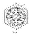
- FIG. 5 is a true cross section including the effect of thread leads.
- the apparatus includes: a nut (10) having four primary right hand thread starts and twenty secondary locking threads with left hand starts; six planetary rollers (14) each having one primary right hand thread start and five secondary left hand locking thread path starts; and a screw shaft (12) having two primary left hand thread starts and no secondary threads or thread paths. Because the roller locking thread paths are female, the roller and shaft can freely roll together and because the shaft has no locking threads to prevent skidding relative to the rollers, their actual instantaneous pitch diameters relative to each other are not rigidly specified.
- Cones 22 and 24 are provided at opposite ends of the planetary roller 14 which can be utilized to move the planetary rollers 14 towards the shaft 12. This causes the actual pitch diameter of the shaft to change, and the roller pitch diameter in contact with the shaft to change. Note that the nut and roller to nut pitch diameters remain constant due to the gear mesh constraints. Alternatively, the cones can be removed from contact from the planetary rollers 14 so that their inertial force moves them away from contact with the screw 12.
- FIG. 6 shows an example of using resultant forces to separate the roller 14 from the shaft 12 and cause it to follow the cones 22 and 24 when the cones are separated.
- This design example is suitable for bidirectional motion but only unidirectional force. Use of inertial restoring forces with symetrical thread profiles would allow bidirectional motion and bidirectional forces.
- the thread shown in Figure 6 is not symmetrical.
- This embodiment of the continuous variable speed drive had a nominal zero shaft motion per nut rotation. Therefore, varying the ratio about this point results in a bidirectional drive. This could be very useful in applications involving a one-direction roughly constant speed meter motor, such as an induction motor where a bidirectional control of axial motion is needed. Other applications might require a variable speed about a given ratio and would not necessarily be bidirectional ratios. This is achieved by selecting the correct number of starts and diameters in the same manner as described earlier.
- This continuously variable speed drive can result in very sizable acceleration rates since all the moving elements (rollers and nut plus primary drive means such as motor) all run at approximately the same speed and kinetic energy storage nearly independent of the instantaneous gear ratio.
- the nut and motor speed are truly independent of the instantaneous ratio.
Landscapes
- Engineering & Computer Science (AREA)
- General Engineering & Computer Science (AREA)
- Mechanical Engineering (AREA)
- Transmission Devices (AREA)
Applications Claiming Priority (2)
| Application Number | Priority Date | Filing Date | Title |
|---|---|---|---|
| US06/518,701 US4526053A (en) | 1983-02-14 | 1983-07-29 | Stabilized apparatus for converting rotational motion to linear motion |
| US518701 | 1983-07-29 |
Publications (2)
| Publication Number | Publication Date |
|---|---|
| EP0133300A1 true EP0133300A1 (fr) | 1985-02-20 |
| EP0133300B1 EP0133300B1 (fr) | 1988-05-11 |
Family
ID=24065108
Family Applications (1)
| Application Number | Title | Priority Date | Filing Date |
|---|---|---|---|
| EP84108875A Expired EP0133300B1 (fr) | 1983-07-29 | 1984-07-26 | Dispositif stabilisé pour transformer un mouvement rotatif en un mouvement linéaire |
Country Status (4)
| Country | Link |
|---|---|
| US (1) | US4526053A (fr) |
| EP (1) | EP0133300B1 (fr) |
| JP (1) | JPS6078154A (fr) |
| DE (1) | DE3471145D1 (fr) |
Cited By (1)
| Publication number | Priority date | Publication date | Assignee | Title |
|---|---|---|---|---|
| WO2016108029A1 (fr) * | 2014-12-29 | 2016-07-07 | Foundation Brakes France | Actionneur lineaire, actuateur de frein a disque, procede de fabrication d'une denture interieure |
Families Citing this family (34)
| Publication number | Priority date | Publication date | Assignee | Title |
|---|---|---|---|---|
| US4648285A (en) * | 1983-02-14 | 1987-03-10 | Millipore Corporation | Apparatus for converting rotational motion to linear motion |
| SE440822B (sv) * | 1984-03-16 | 1985-08-19 | Bo Granbom | Anordning for att omvandla en roterande rorelse till en linjer rorelse |
| US4836338A (en) * | 1988-04-19 | 1989-06-06 | Allied-Signal Inc. | Electrically operated disc brakes |
| US5992258A (en) * | 1996-12-02 | 1999-11-30 | Akebono Brake Industry Co., Ltd. | Rotation/linear motion converting mechanism |
| US7059447B1 (en) * | 1999-12-21 | 2006-06-13 | Ford Global Technologies, Inc. | Automotive vehicle steering system having an electric motor powered linear actuator shaft for turning a steered wheel |
| US6418807B2 (en) * | 2000-03-06 | 2002-07-16 | Tol-O-Matic, Inc. | Stabilizer for ball screw actuator |
| JP2006514236A (ja) * | 2003-02-20 | 2006-04-27 | コンティ・ファスナーズ・アー・ゲー | 低延性材料に使用するためのセルフタッピングスクリュー |
| JP4148121B2 (ja) * | 2003-12-05 | 2008-09-10 | トヨタ自動車株式会社 | 車輌用操舵装置 |
| JP4241572B2 (ja) * | 2004-10-25 | 2009-03-18 | トヨタ自動車株式会社 | 車輌用電動式パワーステアリング装置 |
| US20060266146A1 (en) * | 2005-05-31 | 2006-11-30 | Waide William M | Direct drive electromechanical linear actuators |
| US7942366B2 (en) * | 2005-06-23 | 2011-05-17 | Karem Aircraft, Inc. | Aircraft landing gear with integrated extension, retraction, and leveling feature |
| JP4858288B2 (ja) | 2006-06-22 | 2012-01-18 | トヨタ自動車株式会社 | 回転直線運動変換機構の製造方法及びその実施に使用する治具 |
| JP4516547B2 (ja) * | 2006-06-22 | 2010-08-04 | トヨタ自動車株式会社 | 回転直線運動変換機構 |
| CN101535683B (zh) * | 2006-06-22 | 2012-01-18 | 丰田自动车株式会社 | 旋转直线运动转换机构的制造方法以及用于实施该方法的夹具 |
| JP4428368B2 (ja) * | 2006-08-03 | 2010-03-10 | トヨタ自動車株式会社 | 回転直線運動変換機構の製造方法 |
| WO2008104969A1 (fr) * | 2007-02-26 | 2008-09-04 | Polygon-Tamarisk Ltd | Presse pour produire des pièces à base de poudre par compactage |
| JP5222125B2 (ja) * | 2008-12-25 | 2013-06-26 | 三菱重工業株式会社 | 内歯車加工用樽形ねじ状工具 |
| JP5345587B2 (ja) * | 2010-06-15 | 2013-11-20 | 株式会社日立製作所 | 回転直動変換機構 |
| EA020935B1 (ru) * | 2012-05-11 | 2015-02-27 | Зао "Диаконт" | Электромеханический привод с демпфирующим устройством |
| FR3005130B1 (fr) * | 2013-04-24 | 2015-04-17 | Sonceboz Sa | Actionneur electrique a tige filetee |
| CN103453096B (zh) * | 2013-08-28 | 2016-06-08 | 西北工业大学 | 一种能实现微小导程的滚柱丝杠副 |
| FR3017678B1 (fr) * | 2014-02-14 | 2016-03-04 | Skf Ab | Vis a rouleaux, procede et outil de montage des rouleaux dans une telle vis a rouleaux |
| WO2016061137A1 (fr) * | 2014-10-15 | 2016-04-21 | Usnr, Llc | Dérouleuse électrique |
| US20160222995A1 (en) * | 2015-01-30 | 2016-08-04 | Wagner Spray Tech Corporation | Piston limit sensing for fluid application |
| US10941762B2 (en) | 2015-01-30 | 2021-03-09 | Wagner Spray Tech Corporation | Piston limit sensing and software control for fluid application |
| JP6579853B2 (ja) * | 2015-08-04 | 2019-09-25 | Ntn株式会社 | 電動ブレーキ装置 |
| US10584777B2 (en) * | 2015-08-07 | 2020-03-10 | Aktiebolaget Skf | Roller screw mechanism with cage |
| US12135048B2 (en) | 2017-09-07 | 2024-11-05 | Wagner Spray Tech Corporation | Piston limit sensing for fluid application |
| US20190113117A1 (en) * | 2017-10-16 | 2019-04-18 | Tzu-Ching Hung | Roller Screw Structure and Mechanism Thereof |
| DE102018209819A1 (de) * | 2018-06-18 | 2019-12-19 | Zf Friedrichshafen Ag | Spindelantrieb für eine steer-by-wire-Lenkung sowie steer-by-wire-Lenkung |
| US10731740B1 (en) | 2020-02-10 | 2020-08-04 | Kan Cui | Multiple small-pitch helical drives in linear and rotary actuators |
| KR20220156622A (ko) * | 2020-03-31 | 2022-11-25 | 그라코 미네소타 인크. | 전기 작동식 변위 펌프 |
| AU2021246060B2 (en) | 2020-03-31 | 2026-04-09 | Graco Minnesota Inc. | Electrically operated pump for a plural component spray system |
| US12565877B2 (en) | 2020-03-31 | 2026-03-03 | Graco Minnesota Inc. | Electrically operated linear pump and pump drive |
Citations (6)
| Publication number | Priority date | Publication date | Assignee | Title |
|---|---|---|---|---|
| FR1477775A (fr) * | 1966-03-11 | 1967-04-21 | Dispositif à vis et écrou avec rouleaux satellites filetés | |
| US3406584A (en) * | 1967-08-21 | 1968-10-22 | Roantree Electro Mech Corp | Differential roller nut |
| DE1931861A1 (de) * | 1968-06-27 | 1970-01-08 | Skf Svenska Kullagerfab Ab | Vorrichtung zur Umwandlung einer Drehbewegung in eine geradlinige Bewegung |
| US3508452A (en) * | 1968-04-11 | 1970-04-28 | Roantree Electro Mech Corp | Gearing mechanism |
| US4375770A (en) * | 1979-09-11 | 1983-03-08 | La Technique Integrale, Societe Anonyme Francaise | Releasable screw and nut bearing mechanism |
| GB2111635A (en) * | 1981-12-16 | 1983-07-06 | Bo Granbom | A device for converting a rotary motion to a linear movement |
Family Cites Families (7)
| Publication number | Priority date | Publication date | Assignee | Title |
|---|---|---|---|---|
| US2831363A (en) * | 1955-10-03 | 1958-04-22 | Hupp Corp | Screw actuator |
| BE628366A (fr) * | 1962-02-21 | 1963-05-29 | ||
| US3226809A (en) * | 1962-08-17 | 1966-01-04 | Tech Integrale Sa | Method of manufacturing worm-and-nut devices |
| US3173304A (en) * | 1962-12-19 | 1965-03-16 | Strandgren Carl Bruno | Nut and screw devices |
| SE357241B (fr) * | 1972-04-25 | 1973-06-18 | Skf Ind Trading & Dev | |
| SU737687A1 (ru) * | 1977-05-03 | 1980-05-30 | Владимирский политехнический институт | Планетарна передача винт-гайка качени |
| SU832178A1 (ru) * | 1978-10-12 | 1981-05-23 | Владимирский политехнический институт | Планетарна передача винт-гайка качени |
-
1983
- 1983-07-29 US US06/518,701 patent/US4526053A/en not_active Expired - Fee Related
-
1984
- 1984-07-26 EP EP84108875A patent/EP0133300B1/fr not_active Expired
- 1984-07-26 DE DE8484108875T patent/DE3471145D1/de not_active Expired
- 1984-07-27 JP JP59155679A patent/JPS6078154A/ja active Pending
Patent Citations (7)
| Publication number | Priority date | Publication date | Assignee | Title |
|---|---|---|---|---|
| FR1477775A (fr) * | 1966-03-11 | 1967-04-21 | Dispositif à vis et écrou avec rouleaux satellites filetés | |
| US3406584A (en) * | 1967-08-21 | 1968-10-22 | Roantree Electro Mech Corp | Differential roller nut |
| US3508452A (en) * | 1968-04-11 | 1970-04-28 | Roantree Electro Mech Corp | Gearing mechanism |
| DE1931861A1 (de) * | 1968-06-27 | 1970-01-08 | Skf Svenska Kullagerfab Ab | Vorrichtung zur Umwandlung einer Drehbewegung in eine geradlinige Bewegung |
| US3595094A (en) * | 1968-06-27 | 1971-07-27 | Skf Svenska Kullagerfab Ab | Rack and worm mechanism |
| US4375770A (en) * | 1979-09-11 | 1983-03-08 | La Technique Integrale, Societe Anonyme Francaise | Releasable screw and nut bearing mechanism |
| GB2111635A (en) * | 1981-12-16 | 1983-07-06 | Bo Granbom | A device for converting a rotary motion to a linear movement |
Cited By (1)
| Publication number | Priority date | Publication date | Assignee | Title |
|---|---|---|---|---|
| WO2016108029A1 (fr) * | 2014-12-29 | 2016-07-07 | Foundation Brakes France | Actionneur lineaire, actuateur de frein a disque, procede de fabrication d'une denture interieure |
Also Published As
| Publication number | Publication date |
|---|---|
| US4526053A (en) | 1985-07-02 |
| JPS6078154A (ja) | 1985-05-02 |
| EP0133300B1 (fr) | 1988-05-11 |
| DE3471145D1 (en) | 1988-06-16 |
Similar Documents
| Publication | Publication Date | Title |
|---|---|---|
| US4526053A (en) | Stabilized apparatus for converting rotational motion to linear motion | |
| EP0168942B1 (fr) | Assemblage de vis sans fin et écrou | |
| US3597990A (en) | Zero-lash right-angle movement | |
| US4648285A (en) | Apparatus for converting rotational motion to linear motion | |
| DE69121492T2 (de) | Getriebesystem | |
| EP0077490A2 (fr) | Mécanisme de transmission | |
| US20220034387A1 (en) | Roller drive | |
| JPS6334343A (ja) | 差動遊星歯車装置 | |
| US3730016A (en) | Friction drive differential screw | |
| CN105283692B (zh) | 无级变速机构 | |
| US20130337957A1 (en) | Segmented ground gear transmission (SGGT) | |
| JP7162608B2 (ja) | ガタ防止装置および方法 | |
| CN111779810B (zh) | 一种行星滚柱丝杠 | |
| US6093126A (en) | Transmission device | |
| KR102372783B1 (ko) | 기어박스 | |
| WO2006094535A1 (fr) | Vis a billes | |
| KR20210142197A (ko) | 기어박스 | |
| US4297919A (en) | Mechanical power transmission method and means | |
| US3174354A (en) | Transmission | |
| US4655100A (en) | Rolling element jackscrew | |
| EP0302846A1 (fr) | Broche filetée avec écrous à billes | |
| US4620457A (en) | Nutating drive mechanisms having roller driving elements | |
| US20220099160A1 (en) | Toroidal gearbox for slewing mechanisms | |
| US5546822A (en) | Variable speed torque multiplying transmission | |
| US3442158A (en) | Stepless variable transmission |
Legal Events
| Date | Code | Title | Description |
|---|---|---|---|
| PUAI | Public reference made under article 153(3) epc to a published international application that has entered the european phase |
Free format text: ORIGINAL CODE: 0009012 |
|
| AK | Designated contracting states |
Designated state(s): CH DE FR GB LI NL SE |
|
| 17P | Request for examination filed |
Effective date: 19850403 |
|
| 17Q | First examination report despatched |
Effective date: 19860718 |
|
| GRAA | (expected) grant |
Free format text: ORIGINAL CODE: 0009210 |
|
| AK | Designated contracting states |
Kind code of ref document: B1 Designated state(s): CH DE FR GB LI NL SE |
|
| REF | Corresponds to: |
Ref document number: 3471145 Country of ref document: DE Date of ref document: 19880616 |
|
| ET | Fr: translation filed | ||
| PLBE | No opposition filed within time limit |
Free format text: ORIGINAL CODE: 0009261 |
|
| STAA | Information on the status of an ep patent application or granted ep patent |
Free format text: STATUS: NO OPPOSITION FILED WITHIN TIME LIMIT |
|
| 26N | No opposition filed | ||
| PGFP | Annual fee paid to national office [announced via postgrant information from national office to epo] |
Ref country code: FR Payment date: 19900601 Year of fee payment: 7 |
|
| PGFP | Annual fee paid to national office [announced via postgrant information from national office to epo] |
Ref country code: DE Payment date: 19900619 Year of fee payment: 7 Ref country code: CH Payment date: 19900619 Year of fee payment: 7 |
|
| PGFP | Annual fee paid to national office [announced via postgrant information from national office to epo] |
Ref country code: SE Payment date: 19900621 Year of fee payment: 7 |
|
| PGFP | Annual fee paid to national office [announced via postgrant information from national office to epo] |
Ref country code: GB Payment date: 19900702 Year of fee payment: 7 |
|
| PGFP | Annual fee paid to national office [announced via postgrant information from national office to epo] |
Ref country code: NL Payment date: 19900731 Year of fee payment: 7 |
|
| PG25 | Lapsed in a contracting state [announced via postgrant information from national office to epo] |
Ref country code: GB Effective date: 19910726 |
|
| PG25 | Lapsed in a contracting state [announced via postgrant information from national office to epo] |
Ref country code: SE Effective date: 19910727 |
|
| PG25 | Lapsed in a contracting state [announced via postgrant information from national office to epo] |
Ref country code: LI Effective date: 19910731 Ref country code: CH Effective date: 19910731 |
|
| PG25 | Lapsed in a contracting state [announced via postgrant information from national office to epo] |
Ref country code: NL Effective date: 19920201 |
|
| NLV4 | Nl: lapsed or anulled due to non-payment of the annual fee | ||
| GBPC | Gb: european patent ceased through non-payment of renewal fee | ||
| PG25 | Lapsed in a contracting state [announced via postgrant information from national office to epo] |
Ref country code: FR Effective date: 19920331 |
|
| REG | Reference to a national code |
Ref country code: CH Ref legal event code: PL |
|
| PG25 | Lapsed in a contracting state [announced via postgrant information from national office to epo] |
Ref country code: DE Effective date: 19920401 |
|
| REG | Reference to a national code |
Ref country code: FR Ref legal event code: ST |
|
| EUG | Se: european patent has lapsed |
Ref document number: 84108875.0 Effective date: 19920210 |