EP0133465A1 - Entstörschaltung für Farb-Fernsehgeräte - Google Patents
Entstörschaltung für Farb-Fernsehgeräte Download PDFInfo
- Publication number
- EP0133465A1 EP0133465A1 EP84107318A EP84107318A EP0133465A1 EP 0133465 A1 EP0133465 A1 EP 0133465A1 EP 84107318 A EP84107318 A EP 84107318A EP 84107318 A EP84107318 A EP 84107318A EP 0133465 A1 EP0133465 A1 EP 0133465A1
- Authority
- EP
- European Patent Office
- Prior art keywords
- coil
- supply line
- circuit
- demagnetizing coil
- power supply
- Prior art date
- Legal status (The legal status is an assumption and is not a legal conclusion. Google has not performed a legal analysis and makes no representation as to the accuracy of the status listed.)
- Granted
Links
- 238000004804 winding Methods 0.000 claims abstract description 14
- 230000008878 coupling Effects 0.000 claims abstract description 7
- 238000010168 coupling process Methods 0.000 claims abstract description 7
- 238000005859 coupling reaction Methods 0.000 claims abstract description 7
- 230000001939 inductive effect Effects 0.000 claims abstract description 5
- 229910000859 α-Fe Inorganic materials 0.000 claims abstract description 5
- 230000005347 demagnetization Effects 0.000 abstract description 8
- 230000001629 suppression Effects 0.000 description 4
- 230000005855 radiation Effects 0.000 description 2
- 230000005540 biological transmission Effects 0.000 description 1
- 239000003990 capacitor Substances 0.000 description 1
- 239000004020 conductor Substances 0.000 description 1
- 230000000694 effects Effects 0.000 description 1
- 238000001228 spectrum Methods 0.000 description 1
Images
Classifications
-
- H—ELECTRICITY
- H04—ELECTRIC COMMUNICATION TECHNIQUE
- H04N—PICTORIAL COMMUNICATION, e.g. TELEVISION
- H04N9/00—Details of colour television systems
- H04N9/12—Picture reproducers
- H04N9/16—Picture reproducers using cathode ray tubes
- H04N9/29—Picture reproducers using cathode ray tubes using demagnetisation or compensation of external magnetic fields
Definitions
- the invention relates to a circuit for eliminating the image interference caused by the demagnetizing coil on color picture tubes in television sets due to unavoidable capacitive and / or inductive coupling, in which the demagnetizing coil is connected to the mains lead of the switching power supply.
- Such image disturbances occur passively on the one hand due to the inflow or radiation of high frequency from the network via the predetermined capacitance of the demagnetizing coil to the picture tube mass of approx. 100 - 200 pF and to the anode and to nearby components and conductor tracks and by inductive coupling of the degaussing coil to the deflection system of the color picture tube.
- This creates a shunt to the network that transmits the disturbance into the television set.
- Active interference can reach the demagnetization coil from the switching power supply and the high-voltage generator of the color television set directly into the network or via the deflection coil through capacitive and inductive coupling and can be radiated from there.
- interference filters consisting of an inductance and a capacitance in front of or behind the connection of the demagnetization coil in the power supply line to the switching power supply, to which the demagnetization coil is also connected.
- An LC filter before the demagnetization coil is connected can reduce the passive interference, but not eliminate the active interference md LC filter behind the connection reduce the active interference, but allow the passive interference to penetrate further into the television set.
- the circuit according to the invention solves this problem in that LC filters are provided symmetrically in front of and behind the connection of the degaussing coil, the inductors being housed as identical winding parts on a common bobbin and ferrite core and connected in opposite directions in center taps and the degaussing coil connected to them Center taps is connected.
- This solution has the advantage that high-frequency interference from the network can only penetrate to the demagnetizing coil in a greatly weakened manner and the given capacities of this coil are then no longer sufficient for transmission into the television set.
- the interference caused by the switching power supply and the high-voltage generator only reach the demagnetizing coil in a considerably weakened manner and no longer reach the network.
- the deflection coil of the color picture tube is decoupled from the degaussing coil and the network and the interference radiation by the degaussing coil is eliminated.
- the symmetrical arrangement of the inductances of the two LC filters on a common coil former and ferrite core connecting the partial windings in opposite directions to the center taps for the connection of the demagnetizing coil eliminates any disturbances that may arise from asymmetries of individual chokes and suppresses stray errors.
- each winding is distributed in a known manner to double chambers of the common coil former in order to reduce the winding capacity and the connections of these partial windings form the center taps. This also makes it particularly easy to lead the winding ends out to form the center taps.
- the solution according to the invention also reduces the number of components, simplifies the wiring and saves space in the device.
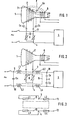
- the color picture tube 1 carries a demagnetizing coil 2, which is connected via a known control circuit R from variable resistances and capacitance at points 3, 4 to the mains supply of the switching power supply 5 in the television set.
- the deflection coil 6 is connected to the DST (diode split) transformer of the high voltage generator in the television set.
- the following disruptive couplings are possible: First, capacitively from and into the network via the capacitances Ca, Cb between the color picture tube anode 7 and the mains lead and via the capacitance Cc between the demagnetizing coil 2 and the deflection coil 6 and, secondly, inductively via the superimposed ones Fields F of these two coils 2, 6.
- the demagnetizing coil 2 on the color picture tube 1 is in turn connected via a control circuit R at points 3, 4 to the mains supply for the switching power supply 5.
- connection points 3, 4 1 LC filter each is provided from the inductors L1 and L3 or L2 and L4 which are identical to one another and the capacitors Cx or Cy.
- the capacitance of the filter located behind the connection points 3, 4 with the inductors L2 + L4 consists of two capacitances Cy of the same size connected in series, their star point is grounded for better symmetry.
- the inductors L1, L2, L3, L4 are all wound in the same direction on a common coil former with a ferrite core 8.
- the coil former (not shown) has, in a known manner, two double chambers for receiving the four windings, the first of which houses the windings of inductors L1, L2 and the second houses the windings of inductors L3, L4. 3, the windings of each double chamber to suppress the stray fields are connected in opposite directions to each other.
- the connections 9, 10 form the input and
- connections 11, 12 the output of the overall filter and the inductors L1 + L3 with the capacitance Cx the LC filter in front of the connection points 3, 4 of the demagnetizing coil 2 and the inductors L2 + L4 with the capacitances Cy the filter behind.
Landscapes
- Engineering & Computer Science (AREA)
- Multimedia (AREA)
- Signal Processing (AREA)
- Video Image Reproduction Devices For Color Tv Systems (AREA)
- Processing Of Color Television Signals (AREA)
- Picture Signal Circuits (AREA)
- Radio Transmission System (AREA)
- Filters And Equalizers (AREA)
Abstract
Description
- Die Erfindung betrifft eine Schaltung zur Beseitigung der von der Entmagnetisierungsspule auf Farbbildröhren in Fernsehgeräten durch unvermeidbare kapazitive und/oder induktive Kopplung bedingten Bildstörungen, bei der die Entmagnetisierungsspule an die Netzzuleitung des Schalt-Netzteils angeschlossen ist.
- Solche Bildstörungen treten einerseits passiv durch Einströmen oder -strahlen von Hochfrequenz aus dem Netz über die vorgegebene Kapazität der Entmagnetisierungsspule zur Bildrohrmasse von rd. 100 - 200 pF und zur Anode und zu nahen Bauteilen und Leiterbahnen und durch induktive Kopplung der Entmagnetisierungsspule zum Ablenksystem der Farbbildröhre auf. Dabei entsteht ein die Störung in das Fernsehgerät übertragender Nebenschluß zum Netz. Aktive Störungen können aus dem Schalt-Netzteil und dem Hochspannungserzeuger des Farb-Fernsehgerätes direkt ins Netz oder über die Ablenkspule durch kapazitive und induktive Kopplung auf die Entmagnetisierungsspule gelangen und von dort großflächig abgestrahlt werden.
- Zur Verringerung solcher Störungen ist es bekannt, in die Netzzuleitung zum Schaltnetzteil, an die auch die Entmagnetisierungsspule angeschlossen ist, aus einer Induktivität und einer Kapazität bestehende Entstörfilter vor oder hinter den Anschluß der Entmagnetisierungsspule zu legen. Ein LC-Filter vor dem Anschluß der Entmagnetisierungsspule kann zwar die passiven Störungen verringern, nicht aber die aktiven Störungen beseitigen md LC-Filter hinter dem Anschluß verringern die aktiven Störungen, lassen aber die passiven Störungen weiter in das Fernsehgerät eindringen.
- Es besteht deshalb die Aufgabe, die bekannten Entstörschaltungen so zu verbessern, daß sowohl die passiven als auch die aktiven Störungen auf ein Minimum herabgesetzt und damit der Sicherheitsabstand zu den vorgeschriebenen Grenzwerten über aktives und passives Störverhalten verbessert wird.
- Die Schaltung laut Erfindung löst diese Aufgabe dadurch, daß LC-Filter symmetrisch vor und hinter dem Anschluß der Entmagnetisierungsspule vorgesehen sind, wobei die Induktivitäten als untereinander gleiche Wicklungsteile auf einem gemeinsamen Spulenkörper und Ferritkern untergebracht und jeweils gegensinnig in Mittelanzapfungen verbunden sind und die Entmagnetisierungsspule an diese Mittelanzapfungen angeschlossen ist.
- Diese Lösung bringt den Vorteil, daß hochfrequente Störungen aus dem Netz nur noch stark abgeschwächt zur Entmagnetisierungsspule vordringen können und die gegebenen Kapazitäten dieser Spule dann nicht mehr zur Übertragung in das Fernsehgerät ausreichen. Auch die vom Schalt-Netzteil und vom Hochspannungserzeuger hervorgerufenen Störungen gelangen nur erheblich geschwächt auf die Entmagnetisierungsspule und erreichen das Netz nicht mehr. Die Ablenkspule der Farbbildröhre ist von der Entmagnetisierungsspule und dem Netz entkoppelt und die Störungs-Abstrahlung durch die Entmagnetisierungsspule beseitigt. Die symmetrische Anordnung der Induktivitäten der beiden LC-Filter auf einem gemeinsamen Spulenkörper und Ferritkern mit gegensinniger Verbindung der Teilwicklungen zu Mittelanzapfungen für den Anschluß der Entmagnetisierungsspule beseitigt aus evtl. Unsymmetrien von Einzeldrosseln bestehende Störungen und unterdrückt Streufehler.
- Die Wirkung dieses Filters läßt sich noch verbessern, wenn uan jede Wicklung zur Verringerung der Wicklungs-Kapazität in bekannter Art auf Doppelkammern des gemeinsamen Spulenkörpers verteilt und die Verbindungen dieser Teilwicklungen die Mittelanzapfungen bilden. Damit wird auch das Herausführen der Wicklungsenden zur Bildung der Mittelanzapfungen besonders einfach.
- Die Lösung laut Erfindung verringert durch die Zusammenfassung der Induktivitäten auch die Zahl der Bauelemente, vereinfacht die Verdrahtung und spart Platz im Gerät.
- Untersuchungen haben gezeigt, daß die wirksame Entkopplung der Entmagnetisierungsspule vom Netz und Schalt-Netzteil das von der Farbröhren-Anode, der Ablenkspule und dem die Störung im Hochspannungserzeuger verursachenden Diode-Split-Trafo ausgestrahlte Störspektrum weiter unter die VDE-Grenzwerte senkt und die bisher übliche besondere Abschirmung des Diode-Split-Trafos wegfallen kann.
- Die Entstörschaltung wird anhand der Zeichnung erläutert. In der Zeichnung zeigen in schematischer Darstellung:
- Fig. 1 den Anschluß der Entmagnetisierungspule und die dabei gegebenen Kopplungsmöglichkeiten und
- Fig. 2 ein Ausführungsbeispiel für die Entstörschaltung lt. Erfindung.
- Laut Fig. 1 trägt die Farbbildröhre 1 eine Entmagnetisierungsspule 2, die über einen bekannten Regelkreis R aus veränderlichen Widerständen und Kapazität an den Punkten 3, 4 an die Netzspeisung des Schalt-Netzteils 5 im Fernsehgerät angeschlossen ist. Die Ablenkspule 6 ist mit dem DST (diode-split)-Trafo des Hochspannungserzeugers im Fernsehgerät verbunden. Dabei sind folgende störende Kopplungen möglich: Einmal kapazitiv vom und in das Netz über die Kapazitäten Ca, Cb zwischen der Farbbildröhren-Anode 7 und der Netzzuleitung und über die Kapazität Cc zwischen der Entmagnetisierungsspule 2 und der Ablenkspule 6 und zum anderen induktiv über die einander überlagernden Felder F dieser beiden Spulen 2, 6.
- Zur Beseitigung der Störungen wird bei der Schaltung lt. Fig. 2 die Entmagnetisierungsspule 2 auf der Farbbildröhre 1 wiederum über einen Regelkreis R an den Punkten 3, 4 an die Netzspeisung für den Schalt-Netzteil 5 angeschlossen.
- Vor und hinter den Anschlußpunkten 3, 4 ist je 1 LC-Filter aus den untereinander gleichen Induktivitäten Ll und L3 bzw. L2 und L4 und den Kapazitäten Cx bzw. Cy vorgesehen. Dabei besteht die Kapazität des hinter den Anschlußpunkten 3, 4 gelegenen Filters mit den Induktivitäten L2 + L4 aus zwei in Reihe geschalteten, gleich großen Kapazitäten Cy, deren Sternpunkt zur besseren Symmetrierung an Masse liegt. Die Induktivitäten Ll, L2, L3, L4 sind alle gleichsinnug auf einem gemeinsamen Spulenkörper mit Ferritkern 8 gewickelt. Der Spulenkörper (nicht dargestellt) hat in bekannter Art für die Aufnahme der vier Wicklungen zwei Doppelkammern, von denen die erste die Wicklungen der Induktivitäten Ll, L2 und die zweite die Wicklungen der Induktivitäten L3, L4 aufnimmt. Gemäß Fig. 3 sind die Wicklungen jeder Doppelkammer zur Unterdrückung der Streufelder gegensinnig zueinander geschaltet. In dieser Schaltung bilden die Anschlüsse 9, 10 den Eingang und
- die Anschlüsse 11, 12 den Ausgang des Gesamtfilters und die Induktivitäten L1 + L3 mit der Kapazität Cx das vor den Anschlußpunkten 3, 4 der Entmagnetisierungsspule 2 liegende LC-Filter und die Induktivitäten L2 + L4 mit den Kapazitäten Cy das dahinter liegende Filter.
- Für die Entstörung haben sich bei einem Farbfernsehgerät mit ..... cm Bildschirm und dafür ausgelegter Entmagnetisierungsspule folgende Werte für die Bauelemente der LC-Filter bewährt:


- Für andere Bildschirmgrößen ist eine entsprechende Anpassung dieser Werte erforderlich.
Claims (2)
Priority Applications (1)
| Application Number | Priority Date | Filing Date | Title |
|---|---|---|---|
| AT84107318T ATE22640T1 (de) | 1983-07-30 | 1984-06-26 | Entstoerschaltung fuer farb-fernsehgeraete. |
Applications Claiming Priority (2)
| Application Number | Priority Date | Filing Date | Title |
|---|---|---|---|
| DE3327655 | 1983-07-30 | ||
| DE19833327655 DE3327655A1 (de) | 1983-07-30 | 1983-07-30 | Entstoerschaltung fuer farb-fernsehgeraete |
Publications (2)
| Publication Number | Publication Date |
|---|---|
| EP0133465A1 true EP0133465A1 (de) | 1985-02-27 |
| EP0133465B1 EP0133465B1 (de) | 1986-10-01 |
Family
ID=6205417
Family Applications (1)
| Application Number | Title | Priority Date | Filing Date |
|---|---|---|---|
| EP84107318A Expired EP0133465B1 (de) | 1983-07-30 | 1984-06-26 | Entstörschaltung für Farb-Fernsehgeräte |
Country Status (4)
| Country | Link |
|---|---|
| EP (1) | EP0133465B1 (de) |
| AT (1) | ATE22640T1 (de) |
| DE (2) | DE3327655A1 (de) |
| ZA (1) | ZA845760B (de) |
Families Citing this family (1)
| Publication number | Priority date | Publication date | Assignee | Title |
|---|---|---|---|---|
| JPH0693589B2 (ja) * | 1989-03-23 | 1994-11-16 | 株式会社村田製作所 | Lcフィルター |
-
1983
- 1983-07-30 DE DE19833327655 patent/DE3327655A1/de not_active Withdrawn
-
1984
- 1984-06-26 DE DE8484107318T patent/DE3460866D1/de not_active Expired
- 1984-06-26 AT AT84107318T patent/ATE22640T1/de not_active IP Right Cessation
- 1984-06-26 EP EP84107318A patent/EP0133465B1/de not_active Expired
- 1984-07-25 ZA ZA845760A patent/ZA845760B/xx unknown
Non-Patent Citations (2)
| Title |
|---|
| FUNK-TECHNIK, 31. Jahrgang, Nr. 20/1976, Munchen, Heidelberg ULRICH FLEISCHMANN "Netzfilter fur den HF- und VHF-Bereich" Seiten 661,662,664 seite 661, bild 4, 5; seite 662, spalte 2, 2. absatz * |
| FUNK-TECHNIK, 37 (1982), Heft 1 Munchen, Heidelberg BERND STUDEMANN "Sperrwandlernetzteil mit kommerziellen Eigenschaften" Seiten 21-25 seite 24, bild 5 * |
Also Published As
| Publication number | Publication date |
|---|---|
| EP0133465B1 (de) | 1986-10-01 |
| DE3327655A1 (de) | 1985-02-07 |
| ZA845760B (en) | 1985-03-27 |
| ATE22640T1 (de) | 1986-10-15 |
| DE3460866D1 (en) | 1986-11-06 |
Similar Documents
| Publication | Publication Date | Title |
|---|---|---|
| DE3832293C2 (de) | Anpassungsschaltung | |
| DE112011101193T5 (de) | Leckstrom-Reduzierungsvorrichtung | |
| DE2536496A1 (de) | Schaltungsanordnung zum trennen zweier signale benachbarter frequenz | |
| DE69006655T2 (de) | Generator zum Erzeugen einer elektrischen Spannung. | |
| DE1291413B (de) | Transformator | |
| EP0133465B1 (de) | Entstörschaltung für Farb-Fernsehgeräte | |
| DE4026416C2 (de) | Ablenkjocheinheit | |
| DE2802507A1 (de) | Ein hohlraumresonator-magnetron aufweisende vorrichtung | |
| DE4421986A1 (de) | Funkentstörfilter | |
| DE2937695C2 (de) | Aufnahmeschaltung für ein Magnetbandgerät | |
| DE2655466B2 (de) | Hochspannungsgenerator für Elektronenstrahlröhren, vorzugsweise für Fernsehempfänger und EDV-Sichtgeräte | |
| DE1591437A1 (de) | Kopplungsschaltung fuer einen Breitband-Transistorverstaerker | |
| DE2355014C2 (de) | Schaltungsanordnung zur Verhinderung unerwünschter Rückkoppelungen für einen ferngespeisten Zwischenverstärker in einem Nachrichtenübertragungssystem | |
| DE19639238C2 (de) | Eingangsabstimmkreis für Fernsehgerät | |
| DE3333712C2 (de) | Mischeranordnung zur Mischung hochfrequenter elektrischer Schwingungen | |
| DE3328659A1 (de) | Hochfrequenzmodulator | |
| CH616790A5 (en) | Remotely fed repeater for data transmission paths | |
| DE2623412A1 (de) | Ferngespeister zwischenverstaerker fuer nachrichtenuebertragungsstrecken | |
| DE2439346C3 (de) | Schaltungsanordnung in einem Fernsehempfangsgerät mit galvanischer Netztrennung zur Unterdrückung zeilenfrequenter Störspannungen | |
| DE2444894A1 (de) | Transformator mit galvanischer trennung der primaer- und sekundaerseite | |
| DE1153413B (de) | Schaltungsanordnung zur Einstellung der Ausgangsamplitude von Zeilenablenktransformatoren | |
| AT400992B (de) | Pulsübertragungsstrecke | |
| DE977637C (de) | Dreikreis-Bandfilter | |
| DE2650599A1 (de) | Hochspannungsmodul fuer fernsehempfaenger | |
| DE957764C (de) | Wicklungsanordnung insbesondere fur Modulationstransformatoren von Sendern mit Gegentakt-B-Verstarkerschaltungen |
Legal Events
| Date | Code | Title | Description |
|---|---|---|---|
| PUAI | Public reference made under article 153(3) epc to a published international application that has entered the european phase |
Free format text: ORIGINAL CODE: 0009012 |
|
| AK | Designated contracting states |
Designated state(s): AT DE FR IT |
|
| 17P | Request for examination filed |
Effective date: 19850315 |
|
| 17Q | First examination report despatched |
Effective date: 19860127 |
|
| GRAA | (expected) grant |
Free format text: ORIGINAL CODE: 0009210 |
|
| AK | Designated contracting states |
Kind code of ref document: B1 Designated state(s): AT DE FR IT |
|
| REF | Corresponds to: |
Ref document number: 22640 Country of ref document: AT Date of ref document: 19861015 Kind code of ref document: T |
|
| REF | Corresponds to: |
Ref document number: 3460866 Country of ref document: DE Date of ref document: 19861106 |
|
| ET | Fr: translation filed | ||
| ITF | It: translation for a ep patent filed | ||
| PLBE | No opposition filed within time limit |
Free format text: ORIGINAL CODE: 0009261 |
|
| STAA | Information on the status of an ep patent application or granted ep patent |
Free format text: STATUS: NO OPPOSITION FILED WITHIN TIME LIMIT |
|
| 26N | No opposition filed | ||
| PGFP | Annual fee paid to national office [announced via postgrant information from national office to epo] |
Ref country code: AT Payment date: 19910502 Year of fee payment: 8 |
|
| PGFP | Annual fee paid to national office [announced via postgrant information from national office to epo] |
Ref country code: FR Payment date: 19910627 Year of fee payment: 8 |
|
| ITTA | It: last paid annual fee | ||
| PGFP | Annual fee paid to national office [announced via postgrant information from national office to epo] |
Ref country code: DE Payment date: 19910802 Year of fee payment: 8 |
|
| PG25 | Lapsed in a contracting state [announced via postgrant information from national office to epo] |
Ref country code: AT Effective date: 19920626 |
|
| PG25 | Lapsed in a contracting state [announced via postgrant information from national office to epo] |
Ref country code: FR Effective date: 19930226 |
|
| PG25 | Lapsed in a contracting state [announced via postgrant information from national office to epo] |
Ref country code: DE Effective date: 19930302 |
|
| REG | Reference to a national code |
Ref country code: FR Ref legal event code: ST |