EP0133549A2 - Phasentrenner von Zweiphasengemisch bei Ringströmungen - Google Patents
Phasentrenner von Zweiphasengemisch bei Ringströmungen Download PDFInfo
- Publication number
- EP0133549A2 EP0133549A2 EP84109146A EP84109146A EP0133549A2 EP 0133549 A2 EP0133549 A2 EP 0133549A2 EP 84109146 A EP84109146 A EP 84109146A EP 84109146 A EP84109146 A EP 84109146A EP 0133549 A2 EP0133549 A2 EP 0133549A2
- Authority
- EP
- European Patent Office
- Prior art keywords
- phase
- flow
- flows
- water accumulation
- inner tube
- Prior art date
- Legal status (The legal status is an assumption and is not a legal conclusion. Google has not performed a legal analysis and makes no representation as to the accuracy of the status listed.)
- Granted
Links
- 239000000203 mixture Substances 0.000 title claims abstract description 11
- 239000007788 liquid Substances 0.000 claims abstract description 15
- XLYOFNOQVPJJNP-UHFFFAOYSA-N water Substances O XLYOFNOQVPJJNP-UHFFFAOYSA-N 0.000 claims abstract description 12
- 238000009825 accumulation Methods 0.000 claims abstract description 10
- 238000005191 phase separation Methods 0.000 abstract description 8
- 238000000926 separation method Methods 0.000 abstract description 3
- 230000005514 two-phase flow Effects 0.000 abstract description 3
- 239000012071 phase Substances 0.000 description 18
- 239000007789 gas Substances 0.000 description 12
- 238000009434 installation Methods 0.000 description 2
- 239000007791 liquid phase Substances 0.000 description 2
- 238000000889 atomisation Methods 0.000 description 1
- 238000005260 corrosion Methods 0.000 description 1
- 230000007797 corrosion Effects 0.000 description 1
- 230000003628 erosive effect Effects 0.000 description 1
- 239000007792 gaseous phase Substances 0.000 description 1
- 238000000034 method Methods 0.000 description 1
- 238000010327 methods by industry Methods 0.000 description 1
- 125000006850 spacer group Chemical group 0.000 description 1
- 239000000725 suspension Substances 0.000 description 1
Images

Classifications
-
- F—MECHANICAL ENGINEERING; LIGHTING; HEATING; WEAPONS; BLASTING
- F15—FLUID-PRESSURE ACTUATORS; HYDRAULICS OR PNEUMATICS IN GENERAL
- F15D—FLUID DYNAMICS, i.e. METHODS OR MEANS FOR INFLUENCING THE FLOW OF GASES OR LIQUIDS
- F15D1/00—Influencing flow of fluids
- F15D1/001—Flow of fluid from conduits such as pipes, sleeves, tubes, with equal distribution of fluid flow over the evacuation surface
-
- B—PERFORMING OPERATIONS; TRANSPORTING
- B01—PHYSICAL OR CHEMICAL PROCESSES OR APPARATUS IN GENERAL
- B01D—SEPARATION
- B01D19/00—Degasification of liquids
- B01D19/0042—Degasification of liquids modifying the liquid flow
- B01D19/0052—Degasification of liquids modifying the liquid flow in rotating vessels, vessels containing movable parts or in which centrifugal movement is caused
- B01D19/0057—Degasification of liquids modifying the liquid flow in rotating vessels, vessels containing movable parts or in which centrifugal movement is caused the centrifugal movement being caused by a vortex, e.g. using a cyclone, or by a tangential inlet
-
- F—MECHANICAL ENGINEERING; LIGHTING; HEATING; WEAPONS; BLASTING
- F22—STEAM GENERATION
- F22B—METHODS OF STEAM GENERATION; STEAM BOILERS
- F22B37/00—Component parts or details of steam boilers
- F22B37/02—Component parts or details of steam boilers applicable to more than one kind or type of steam boiler
- F22B37/26—Steam-separating arrangements
- F22B37/32—Steam-separating arrangements using centrifugal force
Definitions
- the present invention relates to a phase separator according to the preamble of patent claim 1.
- the heat exchangers connected downstream in a steam turbine system are often not suitable for the passage of two-phase mixtures, or the systems are not designed accordingly.
- such two-phase flows are ring flows, i.e. the liquid phase forms a closed film on the tube wall, which completely envelops the gaseous phase flowing as the core inside.
- the proportion of wall film in the total liquid mass flow can be up to 80%.
- the resulting drops are then separated on the one hand by weight forces (impact plates, Pelton blades) and on the other hand by centrifugal forces (deflection separator, cyclone).
- the former solution requires a strong expansion of the flow cross-section in order to reduce the impact speed and to reduce the drag force of the steam or the gas.
- the second solution requires a strong swirl of the flow, which can potentially endanger the downstream apparatus.
- the invention seeks to remedy this.
- the invention is based on the object of no longer mixing the liquid wall film and gas core flow in a phase separator of the type mentioned. By separating the two phases as completely as possible, there is only an insignificant re-entrainment of liquid and gas; the existing phase separation in a ring flow is hereby used for the final separation of the two-phase mixture.
- the advantage of the invention is to be seen essentially in the fact that by using the already existing phase separation in the flow, there is no atomization of the liquid wall film in drops, and therefore no great deceleration of the flow speed and no swirl are necessary.
- the solution can be integrated into existing phase separation vessels to improve operational safety and the effectiveness of phase separation.
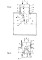
- FIG. 1 shows, in a highly simplified manner, the design of a phase separator with the phase separation of the two-phase mixture according to the invention.
- the ring flow 3 brought up to the inlet connection 1 of a water accumulation 2 is separated into a gas core flow 4 and liquid wall film 6 by an annular passage 12 formed by the inner pipe 5 and the outer pipe 7. While the gas core flow 4 flows through the inner tube 5 and is deflected laterally above the water accumulation 2, the liquid wall film 6 can flow off unhindered. After the two-phase mixture has been separated, the phases no longer come into contact with one another. This is also a prerequisite for being able to avoid the dreaded re-entrainment. In order to really rule out entrainment or carry-over of the liquid, it is advantageous if the lateral deflection is not inclined towards the water accumulation 2.
- phase separator 2 is a section through a further exemplary embodiment of a phase separator, which in turn acts in the inlet connection 1 of a water accumulation 2.
- the phase separator consists of an inner tube 5 which is closed at the end in the flow direction by a baffle plate 10 and which is cut open on one side.
- This opening 11 is covered with a gable-like structure by baffles 8, so that the liquid wall film 6 can run off better on the outer circumference of the inner tube 5 and does not come into contact with the gas core flow 4 flowing out of the opening 11.
- baffles 8 a plurality of spacer plates 9 are installed on the circumference, which can also take over the suspension of the inner tube 5.
- Fig. 3 is a side view of Fig. 2. It shows how the baffles 8 sheath the opening 11 and how it is roofed like a gable.
Landscapes
- Engineering & Computer Science (AREA)
- General Engineering & Computer Science (AREA)
- Physics & Mathematics (AREA)
- Mechanical Engineering (AREA)
- Chemical Kinetics & Catalysis (AREA)
- Chemical & Material Sciences (AREA)
- Fluid Mechanics (AREA)
- Thermal Sciences (AREA)
- Separation Using Semi-Permeable Membranes (AREA)
- Addition Polymer Or Copolymer, Post-Treatments, Or Chemical Modifications (AREA)
- Inorganic Insulating Materials (AREA)
- Optical Communication System (AREA)
- Physical Or Chemical Processes And Apparatus (AREA)
- Separating Particles In Gases By Inertia (AREA)
- Degasification And Air Bubble Elimination (AREA)
Abstract
Description
- Die vorliegende Erfindung betrifft einen Phasentrenner gemäss dem Oberbegriff des Patentanspruchs 1.
- In vielen Anwendungsbereichen, wie z.B. bei Dampfturbinenanlagen, besteht die Notwendigkeit, Flüssigkeit-/ Gas-Zweiphasenströmungen in ihren beiden Phasen trennen zu müssen.
- Bei Dampfturbinenanlagen ist dies insbesondere erforderlich, um das Erosions- und Korrosionspotential des Zweiphasengemisches zu minimalisieren, den auftretenden Druckverlust in den Rohrleitungen zu senken sowie Schläge im System zu vermeiden.
- Des öfteren sind die in einer Dampfturbinenanlage nachgeschalteten Wärmetauscher für den Durchlass von Zweiphasengemisch nicht geeignet, bzw. die Systeme sind nicht dementsprechend ausgelegt.
- Vielfach handelt es sich bei solchen Zweiphasenströmungen um Ringströmungen, d.h. die flüssige Phase bildet an der Rohrwand einen geschlossenen Film, der die als Kern im Innern strömende gasförmige Phase vollständig umhüllt. Der Anteil des Wandfilms am gesamten Flüssigkeitsmassenstrom kann bis zu 80 % betragen.
- Bei Dampfturbinenanlagen werden für die Phasentrennung von Zweiphasengemisch bei Ringströmungen folgende Lösungen angewendet:
- - Einbau von einfachen Prallplatten
- - Anbringen von Pelton-Schaufeln
- - Einbau von Umlenkabscheidern .
- - Zuhilfenahme eines Zyklon-Abscheiders.
- Alle diese Verfahren haben den einen Nachteil gemeinsam, dass die an sich in der Ringströmung bereits vollzogene Phasentrennung nicht Ausgangsbasis für die endgültige separate Ausscheidung der Phasen bildet, sondern es zu einem Re-Entrainment der flüssigen Phase in die Gasströmung kommt.
- Die entstehenden Tropfen werden dann zum einen durch Gewichtskräfte (Prallplatten, Pelton-Schaufeln) und zum anderen durch Zentrifugalkräfte (Umlenkabscheider, Zyklon) abgeschieden.
- Erstere Lösung verlangt eine starke Erweiterung des Strömungsquerschnittes, um die Aufprallgeschwindigkeit herabzusetzen und die Schleppkraft des Dampfes bzw. des Gases zu vermindern. Die zweite Lösung benötigt im Falle des Zyklons einen starken Drall der Strömung, der die nachgeschalteten Apparate potentiell gefährden kann.
- Hier will die Erfindung Abhilfe schaffen.
- Der Erfindung, wie sie in den Ansprüchen gekennzeichnet ist, liegt die Aufgabe zugrunde, bei einem Phasentrenner der eingangs genannten Art die Flüssigkeitswandfilm-und Gaskern-Strömung nicht mehr zu durchmischen. Durch die möglichst vollständige Trennung der beiden Phasen kommt es nur zu einem unwesentlichen Re-Entrainment von Flüssigkeit und Gas; die bereits, vorhandene Phasentrennung in einer Ringströmung wird hiermit zur endgültigen Trennung des Zweiphasengemisches ausgenutzt.
- Der Vorteil der Erfindung ist im wesentlichen darin zu sehen, dass durch die Ausnutzung der bereits vorhandenen Phasentrennung in der Strömung eine Zerstäubung des Flüssigkeitswandfilmes in Tropfen ausbleibt, und deshalb keine grosse Verzögerung der Strömungsgeschwindigkeit und kein Drall mehr notwendig sind.
- Dadurch, dass die Gaskernströmung umgelenkt wird und sodann parallel zur darunterliegenden Wasseransammlung abströmen kann, wird ein durch Aufprall der Gasströmung auf die Wasseroberfläche entstehender Staudruck vermieden.
- Ein weiterer Vorteil ergibt sich aus der Einfachheit und Kompaktheit der konstruktiven Ausführung der erfindungsgemässen Lösung: Eine universelle Verwendungsmöglichkeit ist damit gegeben.
- Des weiteren kann die Lösung in bereits vorhandenen Phasentrenngefässen zur Verbesserung der Betriebssicherheit und Wirksamkeit der Phasentrennung integriert werden.
- Im folgenden sind anhand der Zeichnung Ausführungsbeispiele des Erfindungsgegenstandes vereinfacht dargestellt und näher erläutert. Alle für das Verständnis der Erfindung unwesentlichen Elemente sind nicht dargestellt.
- Es zeigen:
- Fig. 1 einen Phasentrenner mit umgelenktem Innenrohr;
- Fig. 2 einen Phasentrenner mit geradem Innenrohr, seitlicher Oeffnung und Ueberdachung derselben mit Leitblechen und
- Fig. 3 eine seitliche Ansicht von Fig. 2.
- Die Strömungsrichtung der Medien ist mit Pfeilen bezeichnet. In den verschiedenen Figuren sind jeweils gleiche Elemente mit den gleichen Bezugszeichen versehen.
- Fig. 1 zeigt stark vereinfacht die Konzeption eines Phasentrenners mit der erfindungsgemässen Phasentrennung des Zweiphasengemisches. Die am Eintrittsstutzen 1 einer Wasseransammlung 2 herangeführte Ringströmung 3 wird durch einen vom Innenrohr 5 und Aussenrohr 7 gebildeten Kreisringdurchgang 12 in Gaskernströmung 4 und Flüssigkeitswandfilm 6 getrennt. Während die Gaskernströmung 4 durch das Innenrohr 5 strömt und oberhalb der Wasseransammlung 2 seitlich umgelenkt wird, kann der Flüssigkeitswandfilm 6 ungehindert abfliessen. Nach der Trennung des Zweiphasengemisches gelangen die Phasen miteinander nicht mehr in Berührung. Dies ist auch eine Voraussetzung, um das gefürchtete Re-Entrainment umgehen zu können. Um ein Mitreissen oder eine Verschleppung der Flüssigkeit wirklich auszuschliessen, ist es von Vorteil, wenn die seitliche Ablenkung nicht gegen die Wasseransammlung 2 geneigt ist.
- Fig. 2 ist ein Schnitt durch ein weiteres Ausführungsbeispiel eines Phasentrenners, der wiederum im Eintrittsstutzen 1 einer Wasseransammlung 2 wirkt.
- Der Phasentrenner besteht aus einem in Strömungsrichtung am Ende durch eine Prallplatte 10 abgeschlossenes Innenrohr 5, welches auf einer Seite aufgeschnitten ist. Diese Oeffnung 11 ist durch Leitbleche 8 giebelartig überdacht, damit der Flüssigkeitswandfilm 6 besser am Aussenumfang des Innenrohres 5 abrinnen kann und mit der aus der Oeffnung 11 ausströmenden Gaskernströmung 4 nicht in Kontakt kommt. Zwischen Innenrohr 5 und Aussenrohr 7 sind am Umfang mehrere Distanzbleche 9 eingebaut, welche mitunter auch die Aufhängung des Innenrohres 5 übernehmen können.
- Fig. 3 ist eine seitliche Ansicht der Fig. 2. Darin ist ersichtlich, wie die Leitbleche 8 die Oeffnung 11 ummanteln und wie diese giebelartig überdacht ist.
- Die vorgestellten Lösungen können in allen Leitungen eingesetzt werden, in denen Ringströmungen aus Zweiphasengemisch vorherrschen. Dies gilt sowohl für Wasser/Wasserdampfströmungen als auch für beliebige Flüssigkeit/Gasgemische, wie sie allgemein in der Verfahrenstechnik anzutreffen sind. Die unterschiedlichen Volumenanteile zwischen Gaskernströmung 4 und Flüssigkeitswandfilm 6 kann durch eine entsprechende Auslegung des Kreisringdurchganges 12 beherrscht werden.
Claims (2)
Applications Claiming Priority (2)
| Application Number | Priority Date | Filing Date | Title |
|---|---|---|---|
| CH425983 | 1983-08-05 | ||
| CH4259/83 | 1983-08-05 |
Publications (3)
| Publication Number | Publication Date |
|---|---|
| EP0133549A2 true EP0133549A2 (de) | 1985-02-27 |
| EP0133549A3 EP0133549A3 (en) | 1985-04-03 |
| EP0133549B1 EP0133549B1 (de) | 1986-12-30 |
Family
ID=4272787
Family Applications (1)
| Application Number | Title | Priority Date | Filing Date |
|---|---|---|---|
| EP84109146A Expired EP0133549B1 (de) | 1983-08-05 | 1984-08-01 | Phasentrenner von Zweiphasengemisch bei Ringströmungen |
Country Status (6)
| Country | Link |
|---|---|
| EP (1) | EP0133549B1 (de) |
| JP (1) | JPH0711318B2 (de) |
| AU (1) | AU571250B2 (de) |
| CA (1) | CA1239881A (de) |
| DE (1) | DE3461848D1 (de) |
| FI (1) | FI79600B (de) |
Cited By (1)
| Publication number | Priority date | Publication date | Assignee | Title |
|---|---|---|---|---|
| US5250104A (en) * | 1992-10-16 | 1993-10-05 | Texaco Inc. | Method and apparatus for controlling phase splitting at pipe junctions |
Families Citing this family (1)
| Publication number | Priority date | Publication date | Assignee | Title |
|---|---|---|---|---|
| NO20160041A1 (en) | 2016-01-08 | 2017-07-10 | Kanfa As | An arrangement for removing liquid from a flow of natural gas in a gas pipe |
Family Cites Families (11)
| Publication number | Priority date | Publication date | Assignee | Title |
|---|---|---|---|---|
| US1708653A (en) * | 1929-04-09 | A cobpoba | ||
| FR962402A (de) * | 1950-06-10 | |||
| US2122630A (en) * | 1937-01-23 | 1938-07-05 | Superheater Co Ltd | Steam separator |
| CH197075A (de) * | 1937-05-14 | 1938-04-15 | Martin Vermoehlen | Einrichtung zum Abscheiden von Öl und Wasser aus Strömungsmedien in Rohrleitungen. |
| US2228816A (en) * | 1939-01-05 | 1941-01-14 | Gen Electric | Apparatus for separating fluids |
| US2571503A (en) * | 1945-03-19 | 1951-10-16 | Gen Motors Corp | Deaerator and dirt separator |
| US2983331A (en) * | 1957-07-08 | 1961-05-09 | North American Aviation Inc | Inverted flight reservoir |
| US3345803A (en) * | 1965-01-07 | 1967-10-10 | Fmc Corp | Method and apparatus for degassing viscose |
| FR2086768A5 (de) * | 1970-04-08 | 1971-12-31 | Peugeot & Renault | |
| FR2357818A1 (fr) * | 1976-07-05 | 1978-02-03 | Electricite De France | Perfectionnements aux dispositifs secheurs et surchauffeurs de vapeur |
| US4199332A (en) * | 1977-12-07 | 1980-04-22 | Caterpillar Tractor Co. | Deaerator device |
-
1984
- 1984-08-01 DE DE8484109146T patent/DE3461848D1/de not_active Expired
- 1984-08-01 EP EP84109146A patent/EP0133549B1/de not_active Expired
- 1984-08-01 FI FI843038A patent/FI79600B/fi not_active Application Discontinuation
- 1984-08-02 CA CA000460241A patent/CA1239881A/en not_active Expired
- 1984-08-03 JP JP59163024A patent/JPH0711318B2/ja not_active Expired - Lifetime
- 1984-08-03 AU AU31491/84A patent/AU571250B2/en not_active Ceased
Cited By (1)
| Publication number | Priority date | Publication date | Assignee | Title |
|---|---|---|---|---|
| US5250104A (en) * | 1992-10-16 | 1993-10-05 | Texaco Inc. | Method and apparatus for controlling phase splitting at pipe junctions |
Also Published As
| Publication number | Publication date |
|---|---|
| AU3149184A (en) | 1985-02-07 |
| FI843038A7 (fi) | 1985-02-06 |
| EP0133549B1 (de) | 1986-12-30 |
| JPH0711318B2 (ja) | 1995-02-08 |
| FI79600B (fi) | 1989-09-29 |
| CA1239881A (en) | 1988-08-02 |
| FI843038A0 (fi) | 1984-08-01 |
| JPS6057006A (ja) | 1985-04-02 |
| DE3461848D1 (en) | 1987-02-05 |
| EP0133549A3 (en) | 1985-04-03 |
| AU571250B2 (en) | 1988-04-14 |
Similar Documents
| Publication | Publication Date | Title |
|---|---|---|
| DE2411801C2 (de) | Abscheider zum Entfernen von schwereren Bestandteilen aus einem Gasstrom | |
| DE69903196T2 (de) | Vorrichtung zum behandeln einer gas/flüssigkeits-mischung | |
| DE69407109T2 (de) | Apparat zur Trennung von Gas und Flüssigkeit | |
| DE598423C (de) | Fliehkraft-Staubabscheider mit tangentialem Gaseinlass | |
| DE68903434T2 (de) | Einrichtung zur abtrennung von fluessigkeitstroepfchen aus einem gasstrom. | |
| DE19828884C1 (de) | Hochgeschwindigkeitsstoffaustauschboden | |
| EP0014782A1 (de) | Entstaubungseinrichtung | |
| DE69608194T2 (de) | Zentrifugalabschneider, insbesondere für einen Kessel mit zirkulierendem Wirbelbett | |
| DE2301469A1 (de) | Gaswaescheverfahren- und vorrichtung | |
| DE732549C (de) | Anordnung zum Trennen des Dampfwassergemisches in der Trommel eines mit natuerlichem Wasserumlauf betriebenen Roehrendampferzeugers | |
| DE2612917C2 (de) | Vorrichtung zum Abzweigen von Reinigungselementen | |
| EP0133549A2 (de) | Phasentrenner von Zweiphasengemisch bei Ringströmungen | |
| DE2261032A1 (de) | Abscheider fuer feine, in einem traegergas suspendierte feststoffteilchen | |
| DE102008007099B4 (de) | Tropfenabscheidereinheit | |
| DE2513991C3 (de) | Vorrichtung zum Abtrennen von festen und flüssigen Teilchen aus strömenden Gasen durch Zentrifugalkraft | |
| DE102007003436A1 (de) | Verteileinrichtung für einen Fluidstrom | |
| DE2107908A1 (de) | Abscheider und Verfahren zum Ab scheiden von Flüssigkeit aus einem Gas Flussigkeits Gemisch | |
| DE2046642C3 (de) | Abscheider für einen Zentrifugalapparat mit freier Wirbelströmung | |
| DE60210376T2 (de) | Gerät zur Aufteilung einer Zwei-Phasen-Strömung in mehrere Teilströme mit gleichem Flüssigkeit/Gas-Verhältnis | |
| DE19651857C1 (de) | Vorrichtung zur Abscheidung von Feststoffen aus staubbeladenen Abgasen, insbesondere von Verbrennungsanlagen | |
| DE854200C (de) | Vorrichtung zum Abscheiden von festen und fluessigen Beimengungen aus Luft, Gasen und Daempfen | |
| DE4242144A1 (de) | Wasserabscheider | |
| DE68903579T2 (de) | Gas-/fluessigkeit-kontaktvorrichtung. | |
| DE69408766T2 (de) | Vorrichtung und Verfahren zum Entgasen eines Hydraulikkreislaufs | |
| DE3024060A1 (de) | Vorrichtung zur drallabscheidung |
Legal Events
| Date | Code | Title | Description |
|---|---|---|---|
| PUAI | Public reference made under article 153(3) epc to a published international application that has entered the european phase |
Free format text: ORIGINAL CODE: 0009012 |
|
| PUAL | Search report despatched |
Free format text: ORIGINAL CODE: 0009013 |
|
| AK | Designated contracting states |
Designated state(s): BE CH DE FR LI SE |
|
| AK | Designated contracting states |
Designated state(s): BE CH DE FR LI SE |
|
| 17P | Request for examination filed |
Effective date: 19850411 |
|
| GRAA | (expected) grant |
Free format text: ORIGINAL CODE: 0009210 |
|
| AK | Designated contracting states |
Kind code of ref document: B1 Designated state(s): BE CH DE FR LI SE |
|
| BECN | Be: change of holder's name |
Effective date: 19861230 |
|
| REF | Corresponds to: |
Ref document number: 3461848 Country of ref document: DE Date of ref document: 19870205 |
|
| ET | Fr: translation filed | ||
| RAP2 | Party data changed (patent owner data changed or rights of a patent transferred) |
Owner name: BBC BROWN BOVERI AG |
|
| PLBE | No opposition filed within time limit |
Free format text: ORIGINAL CODE: 0009261 |
|
| STAA | Information on the status of an ep patent application or granted ep patent |
Free format text: STATUS: NO OPPOSITION FILED WITHIN TIME LIMIT |
|
| 26N | No opposition filed | ||
| EAL | Se: european patent in force in sweden |
Ref document number: 84109146.5 |
|
| PGFP | Annual fee paid to national office [announced via postgrant information from national office to epo] |
Ref country code: CH Payment date: 19970901 Year of fee payment: 14 |
|
| PG25 | Lapsed in a contracting state [announced via postgrant information from national office to epo] |
Ref country code: LI Free format text: LAPSE BECAUSE OF NON-PAYMENT OF DUE FEES Effective date: 19980831 Ref country code: CH Free format text: LAPSE BECAUSE OF NON-PAYMENT OF DUE FEES Effective date: 19980831 |
|
| REG | Reference to a national code |
Ref country code: CH Ref legal event code: PL |
|
| PGFP | Annual fee paid to national office [announced via postgrant information from national office to epo] |
Ref country code: SE Payment date: 20020725 Year of fee payment: 19 Ref country code: BE Payment date: 20020725 Year of fee payment: 19 |
|
| PGFP | Annual fee paid to national office [announced via postgrant information from national office to epo] |
Ref country code: DE Payment date: 20020809 Year of fee payment: 19 |
|
| PGFP | Annual fee paid to national office [announced via postgrant information from national office to epo] |
Ref country code: FR Payment date: 20020812 Year of fee payment: 19 |
|
| PG25 | Lapsed in a contracting state [announced via postgrant information from national office to epo] |
Ref country code: DE Free format text: LAPSE BECAUSE OF THE APPLICANT RENOUNCES Effective date: 20021213 |
|
| BECH | Be: change of holder |
Free format text: 20020130 *ALSTOM |
|
| BECN | Be: change of holder's name |
Effective date: 20020130 |
|
| PG25 | Lapsed in a contracting state [announced via postgrant information from national office to epo] |
Ref country code: SE Free format text: LAPSE BECAUSE OF NON-PAYMENT OF DUE FEES Effective date: 20030802 |
|
| PG25 | Lapsed in a contracting state [announced via postgrant information from national office to epo] |
Ref country code: BE Free format text: LAPSE BECAUSE OF NON-PAYMENT OF DUE FEES Effective date: 20030831 |
|
| BERE | Be: lapsed |
Owner name: *ALSTOM Effective date: 20030831 |
|
| EUG | Se: european patent has lapsed | ||
| PG25 | Lapsed in a contracting state [announced via postgrant information from national office to epo] |
Ref country code: FR Free format text: LAPSE BECAUSE OF NON-PAYMENT OF DUE FEES Effective date: 20040430 |
|
| REG | Reference to a national code |
Ref country code: FR Ref legal event code: ST |