EP0133579A2 - Steige aus Pappe - Google Patents
Steige aus Pappe Download PDFInfo
- Publication number
- EP0133579A2 EP0133579A2 EP84109465A EP84109465A EP0133579A2 EP 0133579 A2 EP0133579 A2 EP 0133579A2 EP 84109465 A EP84109465 A EP 84109465A EP 84109465 A EP84109465 A EP 84109465A EP 0133579 A2 EP0133579 A2 EP 0133579A2
- Authority
- EP
- European Patent Office
- Prior art keywords
- side wall
- side walls
- articulated
- corner
- fold line
- Prior art date
- Legal status (The legal status is an assumption and is not a legal conclusion. Google has not performed a legal analysis and makes no representation as to the accuracy of the status listed.)
- Granted
Links
- 239000000853 adhesive Substances 0.000 claims abstract description 32
- 230000001070 adhesive effect Effects 0.000 claims abstract description 32
- 235000012055 fruits and vegetables Nutrition 0.000 claims abstract description 4
- 238000013459 approach Methods 0.000 claims description 7
- 239000011324 bead Substances 0.000 claims description 7
- 238000004026 adhesive bonding Methods 0.000 description 4
- 239000010410 layer Substances 0.000 description 4
- 239000000463 material Substances 0.000 description 4
- 235000013399 edible fruits Nutrition 0.000 description 3
- 235000013311 vegetables Nutrition 0.000 description 3
- 239000003292 glue Substances 0.000 description 2
- 230000006835 compression Effects 0.000 description 1
- 238000007906 compression Methods 0.000 description 1
- 238000004080 punching Methods 0.000 description 1
- 230000000284 resting effect Effects 0.000 description 1
- 239000002356 single layer Substances 0.000 description 1
- 230000006641 stabilisation Effects 0.000 description 1
- 238000011105 stabilization Methods 0.000 description 1
- 238000005728 strengthening Methods 0.000 description 1
- XLYOFNOQVPJJNP-UHFFFAOYSA-N water Substances O XLYOFNOQVPJJNP-UHFFFAOYSA-N 0.000 description 1
- 238000004804 winding Methods 0.000 description 1
Images

Classifications
-
- B—PERFORMING OPERATIONS; TRANSPORTING
- B65—CONVEYING; PACKING; STORING; HANDLING THIN OR FILAMENTARY MATERIAL
- B65D—CONTAINERS FOR STORAGE OR TRANSPORT OF ARTICLES OR MATERIALS, e.g. BAGS, BARRELS, BOTTLES, BOXES, CANS, CARTONS, CRATES, DRUMS, JARS, TANKS, HOPPERS, FORWARDING CONTAINERS; ACCESSORIES, CLOSURES, OR FITTINGS THEREFOR; PACKAGING ELEMENTS; PACKAGES
- B65D5/00—Rigid or semi-rigid containers of polygonal cross-section, e.g. boxes, cartons or trays, formed by folding or erecting one or more blanks made of paper
- B65D5/001—Rigid or semi-rigid containers of polygonal cross-section, e.g. boxes, cartons or trays, formed by folding or erecting one or more blanks made of paper stackable
- B65D5/0015—Rigid or semi-rigid containers of polygonal cross-section, e.g. boxes, cartons or trays, formed by folding or erecting one or more blanks made of paper stackable the container being formed by folding up portions connected to a central panel
- B65D5/0045—Rigid or semi-rigid containers of polygonal cross-section, e.g. boxes, cartons or trays, formed by folding or erecting one or more blanks made of paper stackable the container being formed by folding up portions connected to a central panel having both integral corner posts and ledges
Definitions
- the invention relates to a blank for a ' crate made of cardboard, in particular for fruit and vegetables, with a rectangular base part on which side walls are articulated, in the corners between the side walls approaches are hinged to short edges of the side walls, which are parallel to the short edge can be folded several times to form corner supports.
- the invention further relates to a crate which is made from such a blank.
- Such crates are known in many forms. They are generally used to absorb light vegetables or light fruit and must therefore have a certain stability, i.e. load-bearing capacity and compressibility, as well as torsional rigidity even after exposure to moisture.
- the corner supports are provided, which are glued to the side walls.
- the side walls can be double-walled in that a further side wall strip of approximately the same height is articulated on the side wall strip articulated on the base part, which is flat by 180 ° when the crate is erected pressed against the first side wall strip and glued there; becomes. ;
- the known crates are not suitable for taking larger weights, so that wooden crates are used for heavier types of vegetables and fruit, which are relatively expensive on the one hand and are difficult to print on the other hand.
- the wooden crates are made from a wooden floor, wooden side walls and triangular wooden corner supports, the connection being made by nailing.
- the invention is therefore based on the object of designing a crate of the type mentioned at the outset in such a way that the stability and weather resistance are further increased.
- the crate produced with this blank is characterized in that the connecting piece covers the top of the corner support and that the adhesive flap is glued downwards from the top of the corner support to the adjacent side wall.
- the inventive design of the tray ensures that the corner supports pointing upwards with cut edges are covered, so that the corner supports do not soak up water over the cut edges when the tray is in the rain, and on the other hand, by gluing the adhesive flap with the adjacent side wall creates a firm corner connection, which prevents the side wall from tearing off the corner support.
- the width of the first and second fold line of the connecting piece is preferably at least as large as the width of the first and last section of the multi-foldable extension. This ensures that the corner support is completely covered by the connecting piece.
- the first and last section of the approach forms the connection surface for the gluing with the side walls of the crate that meet at the corner.
- the adhesive tab fulfills an additional support function if its length is slightly greater than the height of the adjacent side walls.
- the adhesive flap expediently closes with the lower edge of the side wall, that is to say with the bottom of the crate.
- the adhesive tab therefore leads to a strengthening of the side wall in the corner area, whereby in particular a significant increase in the crush resistance of the corner supports is achieved.
- the corner supports are preferably formed in three parts so that they form a triangle.
- the connecting piece has the shape of a triangle.
- the tray according to the invention is suitable for high loads and is therefore preferably designed with double-walled side walls.
- the side wall strips are with one on their connected to the upper longitudinal edge articulated further side wall strips, which ends in front of the corner support areas of the side walls.
- the double-walled design of the side walls is therefore only between the corner supports, but not in the corner support area.
- the fold line between the two side wall strips is preferably closer to the bottom part than the upper edge of the side wall in the area of the corner supports, so that the side wall in the area of the corner L supports their height, but otherwise has a lower height.
- This folded bead interferes with the corner support resting on the base part. It is therefore advantageous if the first and last section of the extension on the side facing the adjacent side wall are shorter by the height of the folding bead than the central part of the extension. This shorter design causes the parts of the corner support that lie flat against the side walls to rest on the folding bead, while the middle part of the corner support stands directly on the base part. In this way there is a stable support of the corner support downwards.
- the rare wall strips are articulated with the bottom part in the area of the corner supports via a counterfold.
- the creasing is therefore carried out in reverse, i.e. the bead is formed on the underside of the bottom part.
- no folded bead disturbs the support of the corner support on the top of the base part.
- connection piece can be articulated with the adhesive flap on the short side walls as well as on the long side walls.
- the material for the adhesive flap is contained in the rectangular piece of cardboard from which the blank is made.
- the connection piece is articulated with the adhesive flap on the long side wall, the long side in the corner support area is made of two layers, while the end face is made of three layers. While the stability on the long side wall is preferable for reasons of stability, the gluing on the front wall can have advantages when mechanically erecting and gluing the crates.
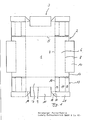
- the blank shown in FIG. 1 consists of a rectangular base part 1, to which two longitudinal side walls 2 and two end side walls 3 are connected via fold lines 4 and 5, respectively.
- the side walls 2, 3 each consist of a first side wall strip 6, 7, to which a second side wall strip 10, 11 is articulated via a further folding line 8, 9 which is parallel to the folding line 4 but is smaller than the folding line 4.
- the second side wall strips 10 and 11 together with the associated first side wall strips 6 and 7 serve to form a double side wall 2 in the central region.
- the short edges 12 of the first side wall strips 7 of the end side walls 3 are followed by three-part approaches 13, which serve to form corner supports.
- the three parts 14, 15, 16 of the extension 13 running parallel to the short edge 12 are separated from one another by fold lines.
- the length of the first part 14 and third part 16, as seen from the short edge 12, is made somewhat shorter towards the adjacent longitudinal side wall 2 than the length of the central part 15.
- the fold line 8 and 9 between the two side wall strips 6, 10 and 7, 11 extends centrally over the side walls 2, 3 to the area in which the corner 13 forms a corner support. At the ends of the side walls 2, 3 pointing towards the corner, they have an upper edge 17, 18, to which second side wall strips 10, 11 no longer connect. In the area of these edges 17, 18, the respective side wall 2, 3 is therefore only formed in one layer.
- the upper edge 17, 18 lies further away from the associated fold line 4 or 5 between the longitudinal side wall 2 or end face wall 3 and bottom part 1 than the fold line 8 or 9 between the two side wall strips 6, 10 or 7, 11 of the side walls 2, 3rd
- the upper edge 18 of the end wall strips 7 is designed as a fold line, via which a triangular connecting piece 19 is articulated to the end wall 3.
- the connecting piece 19 is a right-angled triangle, the second catheter of which is designed as a second fold line 20, which is offset somewhat outwards relative to the short edge 12 of the end wall strip 7.
- an adhesive flap 21 is connected to the connecting piece 19, the length of which is somewhat longer, namely about the thickness of the cardboard material, than the height of the adjacent longitudinal side wall 2 in the region of the edge 17.
- the offset of the second fold line 20 with respect to the short edge 12 of the front side wall 3 allows the corner support formed by the extension 13 to overlap through the connecting piece 19 and the adhesive flap 21 to fold down on the outside of the longitudinal side wall 2.
- the width of the adhesive flap 21 is slightly larger than the width of the first part 14 of the extension 13 and can also be somewhat wider than the upper edge 17 of the longitudinal side wall 2.
- Figure 1 illustrates that the connector 19 and the adhesive tab 21 do not protrude beyond the outer boundary of the rectangular piece of cardboard formed by the remaining blank parts, in particular by the double side walls 2, 3.
- i Connector 19 and adhesive tab 21 can therefore be formed from the same rectangular piece of cardboard when punching the blank, which would also be required without the provision of connector 19 and i adhesive tab 21.
- FIG. 2 shows the crate erected and glued from the blank from FIG. 1.
- the tray consists of a bottom 1, longitudinal side walls 2 and end side walls 3.
- corner supports 22 which are formed from the shoulders 13.
- the side walls 2, 3 are double-walled by folding the second side wall strips 10 and 11 around the folding lines 8 and 9, which are now at the top.
- the triangular corner supports 22 are formed.
- the first part 14 comes to rest flat on the longitudinal side wall 2 and the third part 16 lies flat on the front side wall 3 and is glued there.
- the middle part 15 connects the two parts 14, 16 together as a diagonal.
- the connecting piece 19 is folded down from the upper edge formed as the first fold line 18 of the end face 3 formed in this area so that it covers the upper side of the corner support 22 formed by the parts 14, 15, 16.
- the second fold line 20 of the connecting piece 19 is now due to the offset of the second fold line 20 with respect to the short edge 12 of the end face 3 to the outside somewhat outside of the adjacent longitudinal side wall 2, preferably by exactly the material thickness.
- the adhesive tab 21 can be bent downward and glued flat to the outside of the longitudinal side wall 2.
- the adhesive tab 21 is so long that its the lower edge is flush with the lower edge of the longitudinal side wall 2. In the event of a pressure (compression pressure) acting on the corner support 22 from above, the adhesive tab 21 thus reinforces the corner support 22.
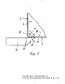
- Figure 3 illustrates the structure of the tray according to the invention in the corner area. Shown is a corner of an upright, already glued to the side walls 2 and 3 and to the corner support 22.
- the connecting piece 19 and the adhesive flap 21 have not yet been bent into their final position and are shown outwardly bent around the first fold line 18 for clarity.
- the corner support 22 is transverse by winding up the parts 14, 15 and 16 of the attachment 13, the first part 14 being glued flat to the adjacent longitudinal side wall 2 and the third part 16 glued flat to the end wall 3.
- the triangle formed by the corner support 22 is covered from above by the connector 19 folded around the first fold line 18, the second fold line 20 coming to lie somewhat outside the crate and allowing the glue flap 21 to be folded down, the glue flap 21 being flat is glued to the outside of the longitudinal side wall 2.
Landscapes
- Engineering & Computer Science (AREA)
- Mechanical Engineering (AREA)
- Cartons (AREA)
Abstract
Description
- Die Erfindung betrifft einen Zuschnitt für eine'Steige aus Pappe, insbesondere für Obst und Gemüse, mit einem rechteckigen Bodenteil, an dem Seitenwände angelenkt sind, wobei in den Ecken zwischen den Seitenwänden Ansätze an kurzen Kanten der Seitenwände angelenkt sind, die parallel zur kurzen Kante zur Bildung von Eckstützen mehrfach faltbar sind. Die Erfindung betrifft weiterhin eine Steige, die aus einem derartigen Zuschnitt hergestellt ist.
- Derartige Steigen sind in vielfacher Ausführungsform bekannt. Sie dienen im allgemeinen zur Aufnahme von leichtem Gemüse oder leichtem Obst und müssen daher eine gewisse Stabilität, also Trag- und Stauchfähigkeit sowie Verwindungssteifigkeit auch nach Einfluß von Feuchtigkeit aufweisen. Zur Erhöhung der Stabilität sind die Eckstützen vorgesehen, die mit den Seitenwänden verklebt werden. Die Seitenwände können dabei doppelwandig ausgebildet sein, indem an dem an dem Bodenteil angelenkten Seitenwandstreifen ein weiterer Seitenwandstreifen etwa gleicher Höhe angelenkt ist, der beim Aufrichten der Steige um 180° flächig gegen den ersten Seitenwandstreifen gedrückt und dort verklebt ; wird. ;
- Die bekannten Steigen eignen sich nicht für die Aufnahme von größeren Gewichten, so daß für schwerere Gemüse- und Obstsorten Holzkisten im Gebrauch sind, die einerseits relativ teuer sind, und sich andererseits schlecht bedrucken lassen. Die Holzsteigen sind aus einem Holzboden, Holzseitenwänden und dreieckigen Holz-Eckstützen hergestellt, wobei die Verbindung durch Nagelung erfolgt.
- Da die Holzsteigen aufgrund ihrer schlechten Bedruckbarkeit eine Herausstellung einer Marke für Obst oder Gemüse bestimmter Herkunft nicht zulassen, hat sich auf diesem Sektor eine Verkaufsstrategie mit Markenartikeln noch nicht durchgesetzt. Diese wäre jedoch ohne weiteres möglich, wenn gut bedruckbare Pappsteigen für diese Anwendungsfälle benutzt werden könnten.
- Der Erfindung liegt daher die Aufgabe zugrunde, eine Steige der eingangs erwähnten Art so auszubilden, daß die Stabilität und Wetterbeständigkeit weiter erhöht wird.
- Diese Aufgabe wird erfindungsgemäß mit einem Zuschnitt der eingangs erwähnten Art dadurch gelöst, daß die mit den Ansätzen ver sehene Seitenwand an ihrer oberen Längsseite über eine erste Falzlinie mit einem Verbindungsstück verbunden ist, an das sich über eine zweite, zu der ersten Falzlinie um 90° gedrehte und gegenüber der Verbindungslinie zwischen Bodenteil und der benach barten Seitenwand etwas nach außen versetzte Falzlinie eine Klebelasche anschließt.
- Die mit diesem Zuschnitt hergestellte Steige zeichnet sich dadurch aus, daß das Verbindungsstück die Oberseite der Eckstütze abdeckt und daß die Klebelasche von der Oberseite der Eckstütze nach unten ragend mit der benachbarten Seitenwand verklebt ist.
- Durch die erfindungsgemäße Ausbildung der Steige wird einerseits erreicht, daß die mit Schnittkanten nach oben zeigenden Eckstützen abgedeckt sind, so daß die Eckstützen sich nicht über die Schnittkanten mit Wasser vollsaugen, wenn die Steige einmal im Regen steht, andererseits wird durch die Verklebung der Klebelasche mit der benachbarten Seitenwand eine feste Eckverbindung erzeugt, die ein Abreißen der Seitenwand von der Eckstütze erschwort.
- Vorzugsweise ist die Breite der ersten und zweiten Falzlinie des Verbindungsstücks mindestens so groß wie die Breite des ersten und letzten Teilstücks des mehrfach faltbaren Ansatzes. Dadurch wird erreicht, daß eine vollständige Abdeckung der Eckstütze durch das Verbindungsstück erfolgt. Das erste und letzte Teilstück des Ansatzes bildet jeweils die Verbindungsfläche für die Verklebung mit den an der Ecke zusammenstoßenden Seitenwänden der Steige.
- Die Klebelasche erfüllt eine zusätzliche Stützfunktion, wenn ihre Länge etwas größer ist als die Höhe der benachbarten Seiten wand. Im verklebten Zustand der Steige schließt die Klebelasche zweckmäßigerweise mit der Unterkante der Seitenwand, also mit dem Boden der Steige,ab. Die Klebelasche führt daher im Eckbereich zu einer Verstärkung der Seitenwand, wodurch insbesondere eine wesentliche Erhöhung der Stauchfestigkeit der Eckstützen erzielt wird.
- Vorzugsweise werden die Eckstützen dreiteilig ausgebildet, so daß sie ein Dreieck bilden. In dieser Ausgestaltung ist es zweck mäßig, wenn das Verbindungsstück die Form eines Dreiecks aufweist.
- Die erfindungsgemäße Steige ist für hohe Lasten geeignet und wird daher vorzugsweise mit doppelwandigen Seitenwänden ausgebildet. Hierzu sind die Seitenwandstreifen mit einem an ihrer oberen Längskante angelenkten weiteren Seitenwandstreifen verbunden, der vor den Eckstützbereichen der Seitenwände endet. Die doppelwandige Ausbildung der Seitenwände geschieht daher nur zwischen den Eckstützen, nicht aber im Eckstützbereich. Dabei ist die Faltlinie zwischen den beiden Seitenwandstreifen vorzugsweise näher am Bodenteil als die Oberkante der Seitenwand im Bereich der Eckstützen, so daß die Seitenwand im Bereich der EckL stützen deren Höhe, im übrigen aber eine niedrigere Höhe aufweist.
- Zur Aufrichtung der Steige ist es wegen des starken Pappmaterial erforderlich, eine Falzrillung vorzusehen. Diese wird üblicherweise so ausgebildet, daß eine mittlere Rillung von der Unter- seite des Bodenteils erfolgt und auf jeder Seite der mittleren Rillung von der Oberseite eine Rillung vorgesehen wird. Dadurch entsteht ein Falzwulst, der nach oben gewölbt ist.
- Dieser Falzwulst stört die Auflage der Eckstütze auf dem Bodenteil. Es ist daher vorteilhaft, wenn der erste und letzte Abschnitt des Ansatzes an der zur benachbarten Seitenwand zeigenden Seite um die Höhe des Falzwulstes kürzer ausgebildet sind als das Mittelteil des Ansatzes. Diese kürzere Ausbildung bewirkt, daß die flächig an den Seitenwänden anliegenden Teile der Eckstütze auf dem Falzwulst aufliegen, während das Mittelteil der Eckstütze direkt auf dem Bodenteil steht. Auf diese Weise findet eine stabile Abstützung der Eckstütze nach unten statt.
- In einer alternativen Ausführungsform sind die Seltenwandstreifen mit dem Bodenteil im Bereich der Eckstützen über einen Gegen falz angelenkt. Im Bereich der Eckstützen wird die Rillung demzufolge umgekehrt ausgeführt, d.h. die Ausbildung des Wulstes erfolgt zur Unterseite des Bodenteils. Demzufolge stört dann an der Oberseite des Bodenteils kein Falzwulst die Auflage der Eckstütze.
- Die größte Stabilität wird erreicht, wenn die Klebelasche von außen mit der benachbarten Seitenwand verklebt ist. Aus maschi- nentechnischen Gründen kann es aber vorteilhaft sein, wenn die Lasche zwischen Seitenwand und Eckstütze geführt und dort verklebt ist.
- Die Anlenkung des Verbindungsstücks mit der Klebelasche kann sowohl an den kurzen Seitenwänden als auch an den langen Seitenwänden erfolgen. In jedem Fall ist das Material für die Klebelasche in dem rechteckigen Pappstück enthalten, aus dem der Zuschnitt hergestellt wird. Bei der Anlenkung an den kurzen Seitenwänden erfolgt eine starke Stabilisierung der langen Seitenwände an denen große Hebelkräfte wirken können. Im Bereich der Eckstütze sind für die lange Seitenwand dann drei Lagen miteinander verklebt, nämlich eine Lage der Eckstütze, die in diesem Bereich einlagige Seitenwand und die Klebelasche. Bei der Anlenkung des Verbindungsstücks mit der Klebelasche an der langen Seitenwand ist die Längsseite im Eckstützenbereich zweilagig, die Stirnseite dagegen dreilagig ausgebildet. Während aus Stabilitätsüberlegungen die Verklebung an der Längsseitenwand vorzuziehen ist, kann die Verklebung an der Stirnseitenwand Vorteile bei der maschinellen Aufrichtung und Verklebung der Steige haben.
- !Die Erfindung soll im folgenden anhand eines in der Zeichnung dargestellten Ausführungsbeispiels näher erläutert werden. Es zeigen:
- Figur 1 einen flachliegenden Zuschnitt für die erfindungs- : gemäße Steige
- Figur 2 eine perspektivische Darstellung der aus dem Zuschnitt aus Figur 1 aufgerichteten und verklebten Steige .
- Figur 3 eine Detaildarstellung des Eckbereichs der Steige vor dem Einschlagen und Verkleben des Verbindungsstücks und der Klebelasche mit der benachbarten Seitenwand.
- Der in Figur 1 dargestellte Zuschnitt besteht aus einem rechteckigen Bodenteil 1, an den sich zwei Längsseitenwände 2 und zwei Stirnseitenwände 3 über Falzlinien 4 bzw. 5 anschließen. Die Seitenwände 2,3 bestehen aus jeweils einem ersten Seitenwandstreifen 6,7, an den über eine parallel zur Falzlinie 4, aber eine kleinere Länge als die Falzlinie 4 aufweisende weitere Faltlinie 8,9 jeweils ein zweiter Seitenwandstreifen 10,11 angelenkt ist. Der zweite Seitenwandstreifen 10 bzw. 11 dient zusammen mit dem zugehörigen ersten Seitenwandstreifen 6 bzw. 7 zur Ausbildung einer doppelten Seitenwand 2 im mittleren Bereich.
- An die kurzen Kanten 12 der ersten Seitenwandstreifen 7 der Stirnseitenwände 3 schließen sich dreiteilige-Ansätze 13 an, die zur Ausbildung von Eckstützen dienen. Die drei parallel zur kurzen Kante 12 verlaufenden Teile 14,15,16 des Ansatzes 13 sind durch Falzlinien voneinander getrennt. Die Länge des von der kurzen Kante 12 aus gesehen ersten Teils 14 und dritten Teils 16 ist zur benachbarten Längsseitenwand 2 hin etwas kürzer ausgebildet als die Länge des mittleren Teils 15.
- Die Faltlinie 8 bzw. 9 zwischen den beiden Seitenwandstreifen 6, 10 bzw. 7,11 erstreckt sich mittig über die Seitenwände 2,3 bis vor den Bereich, in dem durch den Ansatz 13 eine Eckstütze ausgebildet wird. An den zur Ecke zeigenden Enden der Seitenwände 2,3 weisen diese eine obere Kante 17,18 auf, an der jeweils zweite Seitenwandstreifen 10,11 nicht mehr anschließen. Im Bereich dieser Kanten 17,18 ist die jeweilige Seitenwand 2,3 daher nur einlagig ausgebildet.
- Die obere Kante 17,18 liegt weiter von der zugehörigen Falzlinie 4 bzw. 5 zwischen Längsseitenwand 2 bzw. Stirnseitenwand 3 und Bodenteil 1 entfernt als die Faltlinie 8 bzw. 9 zwischen den beiden Seitenwandstreifen 6,10 bzw. 7,11 der Seitenwände 2,3.
- Die obere Kante 18 der Stirnseitenwandstreifen 7 ist als Falzlinie ausgebildet, über die an die Stirnseitenwand 3 ein dreieckiges Verbindungsstück 19 angelenkt ist. Das Verbindungsstück 19 ist ein rechtwinkliges Dreieck, dessen zweite Kathete als zweite Falzlinie 20 ausgebildet ist, die gegenüber der kurzen Kante 12 des Stirnseitenwandstreifens 7 etwas nach außen versetzt ist. Ober die zweite Falzlinie 20 ist mit dem Verbindungsstück 19 eine Klebelasche 21 verbunden, deren Länge etwas - nämlich etwa um die Stärke des Pappmaterials - länger ist als die Höhe der benachbarten Längsseitenwand 2 im Bereich der Kante 17.
- Die Versetzung der zweiten Falzlinie 20 gegenüber der kurzen Kante 12 der Stirnseitenwand 3 nach außen ermöglicht ein übergreifen der durch den Ansatz 13 gebildeten Eckstütze durch das Verbindungsstück 19 und Abklappen der Klebelasche 21 nach unten auf der Außenseite der Längsseitenwand 2. Die Breite der Klebelasche 21 ist etwas größer als die Breite des ersten Teils 14 des Ansatzes 13 und kann auch etwas breiter als die obere Kante 17 der Längsseitenwand 2 sein.
- Figur 1 verdeutlicht, daß das Anschlußteil 19 und die Klebelasche 21 nicht über die äußere Begrenzung des durch die übrigen Zuschnitt-Teile, also insbesondere durch die doppelten Seitenwandungen 2,3, gebildeten rechteckigen Pappstücks hinausragen. i Verbindungsstück 19 und Klebelasche 21 können daher beim Stanzen des Zuschnitts aus demselben rechteckigen Pappstück mitgebildet werden, das auch ohne das Vorsehen von Verbindungsstück 19 und i Klebelasche 21 erforderlich wäre.
- Figur 2 zeigt die aus dem Zuschnitt aus Figur 1 aufgerichtete und verklebte Steige. Die Steige besteht aus einem Boden 1, Längsseitenwänden 2 und Stirnseitenwänden 3. In den Ecken der aufeinanderstoßenden Seitenwände 2,3 befinden sich Eckstützen 22 die aus den Ansätzen 13 gebildet sind. Zwischen den Eckstützen sind die Seitenwände 2,3 doppelwandig ausgebildet durch Herumklappen der zweiten Seitenwandstreifen 10 bzw. 11 um die nunmehr oben liegenden Faltlinien 8 bzw. 9. Durch Einfalten der drei Teile 14,15,16 des Ansatzes 13 entstehen die dreieckigen Eckstützen 22. Das erste Teil 14 kommt dabei flächig an der Längsseitenwand 2 und das dritte Teil 16 flächig an der Stirnseitenwand 3 zur Anlage und ist dort verklebt. Das mittlere Teil 15 verbindet als Diagonale die beiden Teile 14,16 miteinander.
- Von der als erste Falzlinie 18 ausgebildeten oberen Kante der in diesem Bereich einlagig ausgebildeten Stirnseite 3 ist das Verbindungsstück 19 so abgeklappt, daß es die Oberseite der durch die Teile 14,15,16 gebildeten Eckstütze 22 abdeckt. Die zweite Falzlinie 20 des Verbindungsstücks 19 liegt nunmehr aufgrund der Versetzung der zweiten Falzlinie 20 gegenüber der kurzen Kante 12 der Stirnseite 3 nach außen etwas außerhalb der benachbarten Längsseitenwand 2, und zwar vorzugsweise um genau die Material stärke. Dadurch läßt sich die Klebelasche 21 nach unten abbiegen und mit der Außenseite der Längsseitenwand 2 flächig verkleben. Die Klebelasche 21 ist so lang ausgebildet, daß ihre untere Kante mit der unteren Kante der Längsseitenwand 2 abschließt. Im Falle eines auf die Eckstütze 22 von oben wirkenden Druckes (Stauchdruck) verstärkt somit die Klebelasche 21 die Eck- stütze 22.
- Figur 3 verdeutlicht den Aufbau der erfindungsgemäßen Steige im Eckbereich. Dargestellt ist eine Ecke einer aufgerichteten, an den Seitenwänden 2 und 3 sowie zur Eckstütze 22 bereits verklebten Steige. Verbindungsstück 19 und Klebelasche 21 sind noch nicht in ihre endgültige Position gebogen und zur Verdeutlichung nach außen um die erste Falzlinie 18 gebogen dargestellt.
- Die Eckstütze 22 ist durch Aufwicklung der Teile 14,15 und 16 de Ansatzes 13 quergestellt, wobei das erste Teil 14 flächig mit der benachbarten Längsseitenwand 2 und das dritte Teil 16 flächi mit der Stirnseitenwand 3 verklebt sind. Das durch die Eckstütze 22 gebildete Dreieck wird von oben durch das um die erste Falzlinie 18 herumgeklappte Verbindungsstück 19 abgedeckt, wobei die zweite Falzlinie 20 etwas außerhalb der Steige zu liegen kommt und das Herunterklappen der Klebelasche 21 nach unten ermöglicht, wobei die Klebelasche 21 flächig von außen an der Längsseitenwand 2 verklebt wird. Durch das Verbindungsstück 19 wird zusammen mit der Klebelasche 21 eine Eckverbindung zwischen der Stirnseitenwand 3, an die das Verbindungsstück 19 angelenkt ist und der Längsseitenwand 2 hergestellt, mit der die Klebelasche 21 flächig verklebt wird.
Claims (15)
Applications Claiming Priority (2)
| Application Number | Priority Date | Filing Date | Title |
|---|---|---|---|
| DE3329426 | 1983-08-13 | ||
| DE19833329426 DE3329426A1 (de) | 1983-08-13 | 1983-08-13 | Zuschnitt fuer eine steige aus pappe und daraus hergestellte steige |
Publications (3)
| Publication Number | Publication Date |
|---|---|
| EP0133579A2 true EP0133579A2 (de) | 1985-02-27 |
| EP0133579A3 EP0133579A3 (en) | 1986-05-21 |
| EP0133579B1 EP0133579B1 (de) | 1988-11-02 |
Family
ID=6206573
Family Applications (1)
| Application Number | Title | Priority Date | Filing Date |
|---|---|---|---|
| EP84109465A Expired EP0133579B1 (de) | 1983-08-13 | 1984-08-09 | Steige aus Pappe |
Country Status (2)
| Country | Link |
|---|---|
| EP (1) | EP0133579B1 (de) |
| DE (2) | DE3329426A1 (de) |
Cited By (4)
| Publication number | Priority date | Publication date | Assignee | Title |
|---|---|---|---|---|
| NL8600985A (nl) * | 1986-01-29 | 1987-08-17 | Panisello Daniel A Sa | Verbeterd hoeksamenstel voor een kartonnen doos. |
| FR2595080A1 (fr) * | 1986-01-24 | 1987-09-04 | Panisello Daniel A Sa | Ensemble formant coin pour une boite en carton montable et empilable |
| GB2194776A (en) * | 1986-09-05 | 1988-03-16 | Ashton Corrugated | A stacking tray |
| US5992735A (en) * | 1997-06-13 | 1999-11-30 | Veerstroom B.V. | Broadsheet from cardboard for constructing a stackable box and thus obtained box |
Families Citing this family (4)
| Publication number | Priority date | Publication date | Assignee | Title |
|---|---|---|---|---|
| DE8610403U1 (de) * | 1986-04-16 | 1986-06-05 | Herzberger Papierfabrik Ludwig Osthushenrich Gmbh & Co Kg, 3420 Herzberg | Vorgeklebte Aufrichteschachtel |
| DE3614223A1 (de) * | 1986-04-26 | 1987-10-29 | Wolfgang Janzen | Verpackungsschale oder steige aus wellpappe oder vollpappe zum verpacken von produkten |
| DE3626132C1 (en) * | 1986-08-01 | 1987-11-19 | Osthushenrich Kg | Method and device for producing a tray |
| DE3729596A1 (de) * | 1987-09-04 | 1989-03-16 | Hermann Krautter | Verpackungsschale oder steige aus pappe zum verpacken von produkten, vorzugsweise von landwirtschaftlichen produkten |
Family Cites Families (7)
| Publication number | Priority date | Publication date | Assignee | Title |
|---|---|---|---|---|
| FR1192761A (fr) * | 1958-03-07 | 1959-10-28 | Erko Oldenburger Kartonagenfab | Boîte d'emballage pour fruits et autres denrées |
| DE1097351B (de) * | 1958-03-13 | 1961-01-12 | Erko Oldenburger Kartonagenfab | Transportbehaelter aus einem einzigen Zuschnitt von Pappe, vorzugsweise Wellpappe, insbesondere fuer Obst, Gemuese, Kartoffeln u. dgl. |
| FR1239460A (fr) * | 1959-07-17 | 1960-08-26 | Carton Ondule Cuirasse Sa Du | Emballage obtenu par découpage et pliage d'un seul flan de carton |
| GB927863A (en) * | 1959-09-30 | 1963-06-06 | Ashton Containers | Improvements in or relating to cardboard or like trays |
| CH381601A (de) * | 1960-07-07 | 1964-08-31 | Lehner Max | Faltschachtel |
| FR1571502A (de) * | 1968-05-07 | 1969-06-20 | ||
| DE7719798U1 (de) * | 1977-06-24 | 1977-09-29 | Osthushenrich Kg | Aufrichteschachtel |
-
1983
- 1983-08-13 DE DE19833329426 patent/DE3329426A1/de active Granted
-
1984
- 1984-08-09 EP EP84109465A patent/EP0133579B1/de not_active Expired
- 1984-08-09 DE DE8484109465T patent/DE3474945D1/de not_active Expired
Cited By (4)
| Publication number | Priority date | Publication date | Assignee | Title |
|---|---|---|---|---|
| FR2595080A1 (fr) * | 1986-01-24 | 1987-09-04 | Panisello Daniel A Sa | Ensemble formant coin pour une boite en carton montable et empilable |
| NL8600985A (nl) * | 1986-01-29 | 1987-08-17 | Panisello Daniel A Sa | Verbeterd hoeksamenstel voor een kartonnen doos. |
| GB2194776A (en) * | 1986-09-05 | 1988-03-16 | Ashton Corrugated | A stacking tray |
| US5992735A (en) * | 1997-06-13 | 1999-11-30 | Veerstroom B.V. | Broadsheet from cardboard for constructing a stackable box and thus obtained box |
Also Published As
| Publication number | Publication date |
|---|---|
| DE3329426A1 (de) | 1985-02-28 |
| DE3329426C2 (de) | 1988-07-28 |
| EP0133579B1 (de) | 1988-11-02 |
| DE3474945D1 (de) | 1988-12-08 |
| EP0133579A3 (en) | 1986-05-21 |
Similar Documents
| Publication | Publication Date | Title |
|---|---|---|
| DE2824077C2 (de) | Faltschachtel | |
| DE2728365A1 (de) | Faltschachtel, insbesondere fuer fruechte und gemuese | |
| EP0133579B1 (de) | Steige aus Pappe | |
| DE19814093A1 (de) | Faltschachtel | |
| DE68902471T2 (de) | Faltschachtel und zuschnitt dafuer. | |
| DE68908428T2 (de) | Schalenförmige Verpackung aus Karton oder dergleichen. | |
| EP1084958A1 (de) | Vorfaltbares Verpackungstray | |
| DE2632914C2 (de) | Bodenaufbau eines aus mit Kunstharz laminiertem Karton bestehenden Flüssigkeitsverpackungsbehälters | |
| EP0120107A1 (de) | Steige für Obst und Gemüse, Zuschnitt und Verfahren zu ihrer Herstellung | |
| DE20203152U1 (de) | Verpackung | |
| DE7924243U1 (de) | Aufrichteschachtel | |
| DE69607340T2 (de) | Ausgestanzter zuschnitt für eine schalenförmige verpackung | |
| DE2756960C2 (de) | Transportbehälter, Display-Sockel o.dgl | |
| DE102019127917B4 (de) | Faltbodenschachtel mit Automatikboden sowie maschinelles Herstellungsverfahren dafür | |
| DE29901162U1 (de) | Zuschnitt aus faltbarem Material zum Auffalten eines tragfähigen Transportbehältnisses | |
| DE4411371C2 (de) | Flachliegend vormontierte und aufrichtbare Faltschachtel | |
| EP0340319A1 (de) | Faltschachtel | |
| CH691120A5 (de) | Faltbare Ablage- und Umzugschachtel aus Karton, Wellpappe oder aus einem Kunststofflaminat. | |
| DE2457137C2 (de) | Faltschachtel | |
| DE9403716U1 (de) | Behälter aus Wellpappe | |
| EP0328509A1 (de) | Zuschnittbogen für eine Steige aus Pappe, insbesondere Wellpappe | |
| AT3262U1 (de) | Zuschnitt für eine faltschachtel | |
| DE3148868C2 (de) | ||
| DE2637128A1 (de) | Zuschnitt fuer eine rechteckige steige | |
| DE29911204U1 (de) | Bechersteige aus faltbarem Material und Zuschnitt zur Bildung einer Bechersteige |
Legal Events
| Date | Code | Title | Description |
|---|---|---|---|
| PUAI | Public reference made under article 153(3) epc to a published international application that has entered the european phase |
Free format text: ORIGINAL CODE: 0009012 |
|
| AK | Designated contracting states |
Designated state(s): BE DE FR GB IT NL |
|
| PUAL | Search report despatched |
Free format text: ORIGINAL CODE: 0009013 |
|
| AK | Designated contracting states |
Kind code of ref document: A3 Designated state(s): BE DE FR GB IT NL |
|
| 17P | Request for examination filed |
Effective date: 19860704 |
|
| 17Q | First examination report despatched |
Effective date: 19870430 |
|
| GRAA | (expected) grant |
Free format text: ORIGINAL CODE: 0009210 |
|
| AK | Designated contracting states |
Kind code of ref document: B1 Designated state(s): BE DE FR GB IT NL |
|
| GBT | Gb: translation of ep patent filed (gb section 77(6)(a)/1977) | ||
| REF | Corresponds to: |
Ref document number: 3474945 Country of ref document: DE Date of ref document: 19881208 |
|
| ET | Fr: translation filed | ||
| ITF | It: translation for a ep patent filed | ||
| PGFP | Annual fee paid to national office [announced via postgrant information from national office to epo] |
Ref country code: DE Payment date: 19890809 Year of fee payment: 6 |
|
| PLBI | Opposition filed |
Free format text: ORIGINAL CODE: 0009260 |
|
| PLBI | Opposition filed |
Free format text: ORIGINAL CODE: 0009260 |
|
| PGFP | Annual fee paid to national office [announced via postgrant information from national office to epo] |
Ref country code: FR Payment date: 19890825 Year of fee payment: 6 |
|
| ITTA | It: last paid annual fee | ||
| PGFP | Annual fee paid to national office [announced via postgrant information from national office to epo] |
Ref country code: NL Payment date: 19890831 Year of fee payment: 6 Ref country code: GB Payment date: 19890831 Year of fee payment: 6 |
|
| 26 | Opposition filed |
Opponent name: RESEARCHVERENIGING VAN DE NEDERLANDSE GOLFKARTONIN Effective date: 19890731 |
|
| 26 | Opposition filed |
Opponent name: PAPIERFABRIEK DE HOOP H. BOS & ZONEN B.V., Effective date: 19890801 Opponent name: RESEARCHVERENIGING VAN DE NEDERLANDSE GOLFKARTONIN Effective date: 19890731 |
|
| PGFP | Annual fee paid to national office [announced via postgrant information from national office to epo] |
Ref country code: BE Payment date: 19891012 Year of fee payment: 6 |
|
| NLR1 | Nl: opposition has been filed with the epo |
Opponent name: RESEARCHVERENIGING VAN DE NEDERLANDSE GOLFKARTONIN |
|
| NLR1 | Nl: opposition has been filed with the epo |
Opponent name: PAPIERFABRIEK ' DE HOOP ' H. BOS & ZONEN B.V. |
|
| PG25 | Lapsed in a contracting state [announced via postgrant information from national office to epo] |
Ref country code: GB Effective date: 19900809 |
|
| PG25 | Lapsed in a contracting state [announced via postgrant information from national office to epo] |
Ref country code: BE Effective date: 19900831 |
|
| BERE | Be: lapsed |
Owner name: HERZBERGER PAPIERFABRIK LUDWIG OSTHUSHENRICH G.M. Effective date: 19900831 |
|
| PG25 | Lapsed in a contracting state [announced via postgrant information from national office to epo] |
Ref country code: NL Effective date: 19910301 |
|
| GBPC | Gb: european patent ceased through non-payment of renewal fee | ||
| NLV4 | Nl: lapsed or anulled due to non-payment of the annual fee | ||
| RDAG | Patent revoked |
Free format text: ORIGINAL CODE: 0009271 |
|
| STAA | Information on the status of an ep patent application or granted ep patent |
Free format text: STATUS: PATENT REVOKED |
|
| REG | Reference to a national code |
Ref country code: FR Ref legal event code: ST |
|
| 27W | Patent revoked |
Effective date: 19910317 |
|
| GBPR | Gb: patent revoked under art. 102 of the ep convention designating the uk as contracting state |