EP0133602A2 - Mechanische Vorrichtung zum Offenhalten einer Tür, insbesondere Fahrzeugtür - Google Patents
Mechanische Vorrichtung zum Offenhalten einer Tür, insbesondere Fahrzeugtür Download PDFInfo
- Publication number
- EP0133602A2 EP0133602A2 EP84401577A EP84401577A EP0133602A2 EP 0133602 A2 EP0133602 A2 EP 0133602A2 EP 84401577 A EP84401577 A EP 84401577A EP 84401577 A EP84401577 A EP 84401577A EP 0133602 A2 EP0133602 A2 EP 0133602A2
- Authority
- EP
- European Patent Office
- Prior art keywords
- pads
- arm
- door
- guide
- spring
- Prior art date
- Legal status (The legal status is an assumption and is not a legal conclusion. Google has not performed a legal analysis and makes no representation as to the accuracy of the status listed.)
- Ceased
Links
- 230000003042 antagnostic effect Effects 0.000 claims abstract description 7
- 239000002184 metal Substances 0.000 claims description 3
- 230000008602 contraction Effects 0.000 claims description 2
- 230000007246 mechanism Effects 0.000 description 8
- 238000004804 winding Methods 0.000 description 5
- 238000004519 manufacturing process Methods 0.000 description 4
- 239000008188 pellet Substances 0.000 description 4
- 230000009471 action Effects 0.000 description 2
- 238000004873 anchoring Methods 0.000 description 2
- 238000005452 bending Methods 0.000 description 2
- 239000000470 constituent Substances 0.000 description 2
- 238000010276 construction Methods 0.000 description 2
- 230000000694 effects Effects 0.000 description 2
- 230000008961 swelling Effects 0.000 description 2
- 101100536354 Drosophila melanogaster tant gene Proteins 0.000 description 1
- 241001272720 Medialuna californiensis Species 0.000 description 1
- 208000029152 Small face Diseases 0.000 description 1
- 229910000831 Steel Inorganic materials 0.000 description 1
- 239000011324 bead Substances 0.000 description 1
- 238000005256 carbonitriding Methods 0.000 description 1
- 230000015556 catabolic process Effects 0.000 description 1
- 230000006835 compression Effects 0.000 description 1
- 238000007906 compression Methods 0.000 description 1
- 238000005520 cutting process Methods 0.000 description 1
- 230000007423 decrease Effects 0.000 description 1
- 238000010586 diagram Methods 0.000 description 1
- 210000005069 ears Anatomy 0.000 description 1
- 229940082150 encore Drugs 0.000 description 1
- 238000005516 engineering process Methods 0.000 description 1
- 238000002513 implantation Methods 0.000 description 1
- 238000009434 installation Methods 0.000 description 1
- 238000012423 maintenance Methods 0.000 description 1
- 239000000463 material Substances 0.000 description 1
- 238000000034 method Methods 0.000 description 1
- 230000008569 process Effects 0.000 description 1
- 230000000750 progressive effect Effects 0.000 description 1
- 230000001681 protective effect Effects 0.000 description 1
- 230000003252 repetitive effect Effects 0.000 description 1
- 230000000717 retained effect Effects 0.000 description 1
- 230000002441 reversible effect Effects 0.000 description 1
- 125000006850 spacer group Chemical group 0.000 description 1
- 238000003892 spreading Methods 0.000 description 1
- 230000007480 spreading Effects 0.000 description 1
- 239000010959 steel Substances 0.000 description 1
Images

Classifications
-
- E—FIXED CONSTRUCTIONS
- E05—LOCKS; KEYS; WINDOW OR DOOR FITTINGS; SAFES
- E05C—BOLTS OR FASTENING DEVICES FOR WINGS, SPECIALLY FOR DOORS OR WINDOWS
- E05C17/00—Devices for holding wings open; Devices for limiting opening of wings or for holding wings open by a movable member extending between frame and wing; Braking devices, stops or buffers, combined therewith
- E05C17/02—Devices for holding wings open; Devices for limiting opening of wings or for holding wings open by a movable member extending between frame and wing; Braking devices, stops or buffers, combined therewith by mechanical means
- E05C17/04—Devices for holding wings open; Devices for limiting opening of wings or for holding wings open by a movable member extending between frame and wing; Braking devices, stops or buffers, combined therewith by mechanical means with a movable bar or equivalent member extending between frame and wing
- E05C17/12—Devices for holding wings open; Devices for limiting opening of wings or for holding wings open by a movable member extending between frame and wing; Braking devices, stops or buffers, combined therewith by mechanical means with a movable bar or equivalent member extending between frame and wing consisting of a single rod
- E05C17/20—Devices for holding wings open; Devices for limiting opening of wings or for holding wings open by a movable member extending between frame and wing; Braking devices, stops or buffers, combined therewith by mechanical means with a movable bar or equivalent member extending between frame and wing consisting of a single rod sliding through a guide
- E05C17/203—Devices for holding wings open; Devices for limiting opening of wings or for holding wings open by a movable member extending between frame and wing; Braking devices, stops or buffers, combined therewith by mechanical means with a movable bar or equivalent member extending between frame and wing consisting of a single rod sliding through a guide concealed, e.g. for vehicles
Definitions
- the present invention relates to a mechanical device for maintaining a door in the open position.
- the invention applies in particular to the doors of motor vehicles.
- the devices of the type under consideration which for the most part also serve as an opening angle limiter, essentially comprise an arm pivotally mounted at one end on the lateral upright of the frame where the articulation of the door is located.
- the arm left free at its other end, is capable of sliding in a guide which, for its part, is fixed in the blank of the door while facing the attachment end of the arm on the frame.
- the guide constitutes a more or less complex mechanical assembly according to the different technologies proposed, but which generally has, in one way or another, two pads (also called rollers) placed facing each other and at a short distance from one of the 'other so as to define between them a space for the passage of the arm.
- Antagonistic action means are provided to allow elastic spacing of the pads under the action of an external force.
- these means are constituted by a return spring system ensuring the mobility of at least one shoe, the spring being able to be of the torsion type working in compression or in traction, or of the flexion type, such as a spiral or helical spring with extended ends.
- the spreading force of the pads is transmitted, during the movements of the door, by the arm itself which, for this purpose, com relates to at least one face opposite the pads, spacers, generally extra thicknesses, such as bosses or any other similar arrangement, constituting an obstacle to be crossed by the pads.
- the present invention aims to provide a simple, economical and reliable over time.
- the subject of the invention is a mechanical device for holding a door in the open position, in particular a motor vehicle door, comprising a sliding arm in a guide having two pads placed facing each other and at short distance l one of the other so as to provide a space between them for the passage of the arm, the latter being provided on at least one of its faces facing the pads with means for spacing said pads, means with elastic antagonistic action being provided in the guide to oppose the spacing of the pads by the sliding arm, device characterized in that the guide has at least one support surface element of cylindrical external shape, mechanically linked to the pads and radially deformable by expansion and contraction, respectively during the spacing and the approximation of the pads, and in that the means with elastic counteracting action consist of at least one helical spring mounted coaxially around and in contact with said surface surface element support.
- the spring support surface member and the pads form a one-piece body.
- this body is a hollow cylinder crossed perpendicularly by the arm in its middle part and equipped with a spring on each of its end parts, the axis of the springs being collinear with the longitudinal axis of the body. More preferably, the pads are placed inside the cylinder.
- the turns of the spring or springs have their internal surface, in contact with the support surface, of planar shape, in order to obtain a maximum contact surface with the support surface element.
- the turns are of quadrangular section, such as square or rectangular.
- the invention consists, in its fundamental characteristics, in making a helical type spring in swelling, in other words in an "anti-mechanical” manner, totally foreign to the usual specific deformation modes of this type of spring.
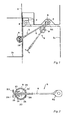
- FIGS. 2, 3 and 4 represent mechanisms according to the invention in their real size.
- the device 5 comprises an arm 6, formed of a flat metal rod, and pivotally mounted at one of its ends around an axis 7 parallel to the axis of articulation 4 of the door and housed in a recess 8 of the upright 1.
- This arm left free at its other end slides in a guide body 9 which, for its part, is fixed on the internal face of the upright 10 of the door, opposite the recess 8 when the door is closed.
- the guide body 9 is a hollow cylindrical body, with a long axis tudinal L, provided at each end with an ear 11, 11 'for fixing on the door.
- the body 9 is a metallic piece of sheet metal wound with non-contiguous edges so as to provide a longitudinal slot 12 allowing a radial deformation of the piece.
- two pads 13, 14 formed by folding inwardly edge tabs initially provided for this purpose when cutting the sheet before winding.
- a lumen 20 is also provided in the middle part of the body 9 in a position diametrically opposite that of the space 15 between the pads, in order to define with this space a corridor for the passage of the sliding arm 6.
- the arm 6 crosses the body 9 in its middle part perpendicular to the longitudinal axis L of the body.
- the arm 6 has, on its large faces opposite the pads of the body 9, opposite bosses 21 and 22 whose inter-vertex distance is slightly greater than the nominal spacing of the pads.
- the bosses 21, 22 located in the vicinity of the free end of the arm are produced simply by an operation of cold deformation of the material, usually called “breakdown” operation, and which consists schematically after notching, stamping the central part and the two edge parts in opposite directions.
- Bosses are thus obtained which form ramps with an asymmetrical longitudinal profile having, in the direction going from the anchoring end 55 of the arm towards its free end, a gentle uphill slope followed, after the top of the boss, by a steep downhill slope forming a locking notch in which a shoe is housed, thus ensuring the maintenance of the door in the open position.
- the door is kept in the open position 3B thanks to the stiff front which the boss opposes to the pads in the direction of closing the door.
- provision may be made for folding at the end of the arm 6 so as to form bent end portions 23, 24 which constitute stops for stopping the pads and consequently limiting the angle of door opening.
- the invention therefore essentially consists in operating a helical spring in swelling by unwinding of the turns under the effect of the spacing of the pads.
- the guide body 40 of the sliding arm 41 is a short cylinder, this time coaxial with the arm and formed of two half-moon pellets 42, 43 applied against one another by their base of so as to present between them a spacing slot 44 having a function similar to the slot 12 described above.
- the central part of the body 40 is hollowed out in order to provide a passage 45 for the arm, the lips of this passage being constituted by beads forming the pads.
- the cohesion of the assembly of the pellets is ensured by a helical spring 48 placed around and in contact with the exterior surface of the pellets.
- a protective casing 49 comprising a main receptacle 50 and a flap closure plate 51, the receptacle and the plate being provided with ears for the installation of the fixing means on the door.
- bosses 52 of the arm as well as the stop 53 limiting the opening angle of the door, are produced, as can be seen, from an arm in two strands folded one against the other and forming at one end a ring 54 for receiving the hinge pin.
- a body 50 slightly in the form of a diabolo, that is to say of external length desired to receive the spring but whose thickness decreases from the periphery to its central part to avoid the functional drawback too wide skates.
- the device according to the invention has numerous advantages compared to its current competitors on the market.
- the guide body 9 carrying the springs oriented perpendicularly to the sliding arm can be produced by winding a sheet of commercially available steel sheet that subsequently subjected to a surface carbonitriding treatment in order to give it the desirable mechanical properties for work in fatigue by repetitive bending of small amplitude to which it must be subjected.
- the force for unlocking the door with a view to closing it can be adjusted by adjusting the curvature of the pads so as to obtain an adequate angle of attack of the latter against the steep front of the bosses.
- the simplicity of the device according to the invention and its small size allow multiple different implantation possibilities.
- the arrangement of the pads 13 and 14 inside the guide body 9 is in no way mandatory. It is indeed quite possible, without harming the essential qualities of the device, to perform the folds tie the rolled sheet, forming the guide body, towards the outside of the body, the important thing being, of course, to realize the two folds in the same direction to obtain two pads facing each other.
- the arm be of flat shape, as well as rectilinear, any other provisions, in this regard, which may be suitable within limits that the skilled person will be able to determine according to his wishes or needs.
Landscapes
- Engineering & Computer Science (AREA)
- Mechanical Engineering (AREA)
- Lock And Its Accessories (AREA)
- Automotive Seat Belt Assembly (AREA)
- Closing And Opening Devices For Wings, And Checks For Wings (AREA)
- Passenger Equipment (AREA)
- Holding Or Fastening Of Disk On Rotational Shaft (AREA)
Applications Claiming Priority (2)
| Application Number | Priority Date | Filing Date | Title |
|---|---|---|---|
| FR8313197 | 1983-08-11 | ||
| FR8313197A FR2550575B1 (fr) | 1983-08-11 | 1983-08-11 | Dispositif mecanique de maintien d'une porte en position d'ouverture, notamment d'une porte de vehicule automobile |
Publications (2)
| Publication Number | Publication Date |
|---|---|
| EP0133602A2 true EP0133602A2 (de) | 1985-02-27 |
| EP0133602A3 EP0133602A3 (de) | 1985-04-10 |
Family
ID=9291562
Family Applications (1)
| Application Number | Title | Priority Date | Filing Date |
|---|---|---|---|
| EP84401577A Ceased EP0133602A3 (de) | 1983-08-11 | 1984-07-26 | Mechanische Vorrichtung zum Offenhalten einer Tür, insbesondere Fahrzeugtür |
Country Status (6)
| Country | Link |
|---|---|
| EP (1) | EP0133602A3 (de) |
| JP (1) | JPS60133177A (de) |
| BR (1) | BR8404009A (de) |
| CA (1) | CA1231504A (de) |
| ES (1) | ES281376Y (de) |
| FR (1) | FR2550575B1 (de) |
Cited By (2)
| Publication number | Priority date | Publication date | Assignee | Title |
|---|---|---|---|---|
| WO2000049257A1 (en) * | 1999-01-29 | 2000-08-24 | Ventra Group Inc. | Door check device |
| US6687953B1 (en) | 2000-10-13 | 2004-02-10 | Ventra Group Inc. | Torsion spring door check device |
Family Cites Families (1)
| Publication number | Priority date | Publication date | Assignee | Title |
|---|---|---|---|---|
| DE461590C (de) * | 1924-02-27 | 1928-06-23 | Hermann Potthoff | Reibungsfeder |
-
1983
- 1983-08-11 FR FR8313197A patent/FR2550575B1/fr not_active Expired
-
1984
- 1984-07-26 EP EP84401577A patent/EP0133602A3/de not_active Ceased
- 1984-08-10 BR BR8404009A patent/BR8404009A/pt unknown
- 1984-08-10 ES ES1984281376U patent/ES281376Y/es not_active Expired
- 1984-08-10 CA CA000460778A patent/CA1231504A/en not_active Expired
- 1984-08-10 JP JP16770484A patent/JPS60133177A/ja active Pending
Cited By (2)
| Publication number | Priority date | Publication date | Assignee | Title |
|---|---|---|---|---|
| WO2000049257A1 (en) * | 1999-01-29 | 2000-08-24 | Ventra Group Inc. | Door check device |
| US6687953B1 (en) | 2000-10-13 | 2004-02-10 | Ventra Group Inc. | Torsion spring door check device |
Also Published As
| Publication number | Publication date |
|---|---|
| CA1231504A (en) | 1988-01-19 |
| FR2550575A1 (fr) | 1985-02-15 |
| EP0133602A3 (de) | 1985-04-10 |
| JPS60133177A (ja) | 1985-07-16 |
| ES281376Y (es) | 1985-10-16 |
| FR2550575B1 (fr) | 1985-11-29 |
| BR8404009A (pt) | 1985-07-16 |
| ES281376U (es) | 1985-02-16 |
Similar Documents
| Publication | Publication Date | Title |
|---|---|---|
| FR2508090A1 (fr) | Dispositif d'entrainement de fil pour moyen de reglage de fenetre | |
| EP2021647B1 (de) | Wegminderungsaktuator, speziell für eine kraftfahrzeugkupplung | |
| EP0241319A1 (de) | Türfeststeller, insbesondere für Kraftfahrzeugtüren | |
| FR2503233A1 (fr) | Dispositif de reglage de position, notamment installation combinee de manoeuvre de vitre et de verrouillage central de porte de vehicule automobile | |
| FR2661958A1 (fr) | Dispositif formant palier de butee. | |
| FR2753574A1 (fr) | Contacteur tournant a ruban, en particulier pour vehicules automobiles | |
| FR2811007A1 (fr) | Charniere avec arret de porte integre | |
| FR2600603A1 (fr) | Tendeur sur un enrouleur de ceinture de securite | |
| EP0479673B1 (de) | Getriebemotor mit seinem Gehäuseverschlussdeckel, insbesondere für eine Scheibenwischeranlage | |
| EP0685374B1 (de) | Getriebemotor, insbesondere für eine Fahrzeugscheibenwischeranlage | |
| EP4392834A1 (de) | Uhr, die ein zifferblatt mit mindestens einem fenster und eine schliessvorrichtung dieses fensters umfasst | |
| EP0603085B1 (de) | Scheibenwischer mit Drehdämpfer, insbesondere für Kraftfahrzeuge | |
| EP0754832B1 (de) | Scharnier für den Gehäusedeckel eines Kochgerätes | |
| EP0133602A2 (de) | Mechanische Vorrichtung zum Offenhalten einer Tür, insbesondere Fahrzeugtür | |
| EP0443919B1 (de) | Scharnier mit integriertem Feststeller für Fahrzeugtüre oder andere Flügel | |
| FR3056959A1 (fr) | Mecanisme pour un element de carrosserie de vehicule | |
| FR2769037A1 (fr) | Dispositif de verrouillage comportant un doigt de transmission commande par came | |
| EP0054449B1 (de) | Fensterheber | |
| EP1788176B1 (de) | Türscharnier mit integriertem Türfeststeller | |
| FR2750185A1 (fr) | Mecanisme pour commander un organe de sortie rotatif au moyen d'un poignee, et siege comportant un tel mecanisme | |
| FR2885639A1 (fr) | Ensemble charniere de porte de vehicule a mecanisme d'arret de porte integre. | |
| FR2818792A3 (fr) | Interrupteur auto-adaptable, particulierement pour le controle des feux de stop d'un vehicule automobile | |
| EP1596127A1 (de) | Fixierung einer Torsionsfeder zwischen zwei Teilen eines Kraftfahrzeugscheinwerfers | |
| FR2526735A1 (fr) | Cendrier, notamment pour vehicules automobiles | |
| FR2898553A1 (fr) | Mecanisme de reglage comportant un tel dispositif de verrouillage et siege de vehicule comportant un tel mecanisme. |
Legal Events
| Date | Code | Title | Description |
|---|---|---|---|
| PUAI | Public reference made under article 153(3) epc to a published international application that has entered the european phase |
Free format text: ORIGINAL CODE: 0009012 |
|
| PUAL | Search report despatched |
Free format text: ORIGINAL CODE: 0009013 |
|
| AK | Designated contracting states |
Designated state(s): DE GB IT SE |
|
| AK | Designated contracting states |
Designated state(s): DE GB IT SE |
|
| 17P | Request for examination filed |
Effective date: 19850928 |
|
| 17Q | First examination report despatched |
Effective date: 19860715 |
|
| STAA | Information on the status of an ep patent application or granted ep patent |
Free format text: STATUS: THE APPLICATION HAS BEEN REFUSED |
|
| 18R | Application refused |
Effective date: 19870907 |
|
| RIN1 | Information on inventor provided before grant (corrected) |
Inventor name: DIEUDONNE, JEAN-PIERRE Inventor name: STEINER, MICHEL |