EP0133638A2 - Thermofarbband sowie Verfahren zu dessen Herstellung - Google Patents
Thermofarbband sowie Verfahren zu dessen Herstellung Download PDFInfo
- Publication number
- EP0133638A2 EP0133638A2 EP84106648A EP84106648A EP0133638A2 EP 0133638 A2 EP0133638 A2 EP 0133638A2 EP 84106648 A EP84106648 A EP 84106648A EP 84106648 A EP84106648 A EP 84106648A EP 0133638 A2 EP0133638 A2 EP 0133638A2
- Authority
- EP
- European Patent Office
- Prior art keywords
- thermal
- plastic film
- ribbon
- wax
- coating material
- Prior art date
- Legal status (The legal status is an assumption and is not a legal conclusion. Google has not performed a legal analysis and makes no representation as to the accuracy of the status listed.)
- Granted
Links
- 238000004519 manufacturing process Methods 0.000 title description 3
- 239000002985 plastic film Substances 0.000 claims abstract description 31
- 229920006255 plastic film Polymers 0.000 claims abstract description 31
- 239000000463 material Substances 0.000 claims abstract description 25
- 230000008018 melting Effects 0.000 claims abstract description 22
- 238000002844 melting Methods 0.000 claims abstract description 22
- 239000007788 liquid Substances 0.000 claims abstract description 6
- 239000001993 wax Substances 0.000 claims description 27
- 238000000034 method Methods 0.000 claims description 24
- 239000011248 coating agent Substances 0.000 claims description 18
- 238000000576 coating method Methods 0.000 claims description 18
- -1 polyethylene Polymers 0.000 claims description 8
- 239000004698 Polyethylene Substances 0.000 claims description 3
- 229920000573 polyethylene Polymers 0.000 claims description 3
- 239000002904 solvent Substances 0.000 claims description 3
- DSEKYWAQQVUQTP-XEWMWGOFSA-N (2r,4r,4as,6as,6as,6br,8ar,12ar,14as,14bs)-2-hydroxy-4,4a,6a,6b,8a,11,11,14a-octamethyl-2,4,5,6,6a,7,8,9,10,12,12a,13,14,14b-tetradecahydro-1h-picen-3-one Chemical compound C([C@H]1[C@]2(C)CC[C@@]34C)C(C)(C)CC[C@]1(C)CC[C@]2(C)[C@H]4CC[C@@]1(C)[C@H]3C[C@@H](O)C(=O)[C@@H]1C DSEKYWAQQVUQTP-XEWMWGOFSA-N 0.000 claims description 2
- 239000002253 acid Substances 0.000 claims description 2
- 235000013871 bee wax Nutrition 0.000 claims description 2
- 239000012166 beeswax Substances 0.000 claims description 2
- 235000013869 carnauba wax Nutrition 0.000 claims description 2
- 239000004203 carnauba wax Substances 0.000 claims description 2
- 150000002334 glycols Chemical class 0.000 claims description 2
- 239000012188 paraffin wax Substances 0.000 claims description 2
- 229920000151 polyglycol Polymers 0.000 claims description 2
- 239000010695 polyglycol Substances 0.000 claims description 2
- 229920001296 polysiloxane Polymers 0.000 claims description 2
- 239000004094 surface-active agent Substances 0.000 claims description 2
- 238000010020 roller printing Methods 0.000 claims 1
- 238000009736 wetting Methods 0.000 claims 1
- 239000011368 organic material Substances 0.000 abstract description 4
- 238000003860 storage Methods 0.000 description 6
- 239000000975 dye Substances 0.000 description 4
- 230000005012 migration Effects 0.000 description 4
- 238000013508 migration Methods 0.000 description 4
- 239000000203 mixture Substances 0.000 description 4
- 229920000139 polyethylene terephthalate Polymers 0.000 description 4
- 239000005020 polyethylene terephthalate Substances 0.000 description 4
- UHOVQNZJYSORNB-UHFFFAOYSA-N Benzene Chemical compound C1=CC=CC=C1 UHOVQNZJYSORNB-UHFFFAOYSA-N 0.000 description 3
- YXFVVABEGXRONW-UHFFFAOYSA-N Toluene Chemical compound CC1=CC=CC=C1 YXFVVABEGXRONW-UHFFFAOYSA-N 0.000 description 3
- 239000006229 carbon black Substances 0.000 description 3
- 239000000839 emulsion Substances 0.000 description 3
- 150000002148 esters Chemical class 0.000 description 3
- 239000012876 carrier material Substances 0.000 description 2
- 238000000354 decomposition reaction Methods 0.000 description 2
- 239000003973 paint Substances 0.000 description 2
- 239000000049 pigment Substances 0.000 description 2
- 229920003023 plastic Polymers 0.000 description 2
- 239000004033 plastic Substances 0.000 description 2
- 239000000126 substance Substances 0.000 description 2
- 229920002554 vinyl polymer Polymers 0.000 description 2
- OKTJSMMVPCPJKN-UHFFFAOYSA-N Carbon Chemical compound [C] OKTJSMMVPCPJKN-UHFFFAOYSA-N 0.000 description 1
- 239000004215 Carbon black (E152) Substances 0.000 description 1
- RYGMFSIKBFXOCR-UHFFFAOYSA-N Copper Chemical compound [Cu] RYGMFSIKBFXOCR-UHFFFAOYSA-N 0.000 description 1
- CTQNGGLPUBDAKN-UHFFFAOYSA-N O-Xylene Chemical compound CC1=CC=CC=C1C CTQNGGLPUBDAKN-UHFFFAOYSA-N 0.000 description 1
- 239000004952 Polyamide Substances 0.000 description 1
- 239000004743 Polypropylene Substances 0.000 description 1
- 239000004793 Polystyrene Substances 0.000 description 1
- 239000004372 Polyvinyl alcohol Substances 0.000 description 1
- XBDQKXXYIPTUBI-UHFFFAOYSA-M Propionate Chemical compound CCC([O-])=O XBDQKXXYIPTUBI-UHFFFAOYSA-M 0.000 description 1
- 239000000853 adhesive Substances 0.000 description 1
- 230000001070 adhesive effect Effects 0.000 description 1
- 230000015572 biosynthetic process Effects 0.000 description 1
- 230000000903 blocking effect Effects 0.000 description 1
- 229910052799 carbon Inorganic materials 0.000 description 1
- 239000000969 carrier Substances 0.000 description 1
- 230000000052 comparative effect Effects 0.000 description 1
- 239000002131 composite material Substances 0.000 description 1
- 150000001875 compounds Chemical class 0.000 description 1
- 238000001816 cooling Methods 0.000 description 1
- 229910052802 copper Inorganic materials 0.000 description 1
- 239000010949 copper Substances 0.000 description 1
- 230000007812 deficiency Effects 0.000 description 1
- 230000008021 deposition Effects 0.000 description 1
- 230000008020 evaporation Effects 0.000 description 1
- 238000001704 evaporation Methods 0.000 description 1
- 239000004744 fabric Substances 0.000 description 1
- 239000003502 gasoline Substances 0.000 description 1
- 238000010438 heat treatment Methods 0.000 description 1
- 229930195733 hydrocarbon Natural products 0.000 description 1
- 150000002430 hydrocarbons Chemical class 0.000 description 1
- 239000000155 melt Substances 0.000 description 1
- 238000010327 methods by industry Methods 0.000 description 1
- 239000002052 molecular layer Substances 0.000 description 1
- 229920000847 nonoxynol Polymers 0.000 description 1
- SNQQPOLDUKLAAF-UHFFFAOYSA-N nonylphenol Chemical class CCCCCCCCCC1=CC=CC=C1O SNQQPOLDUKLAAF-UHFFFAOYSA-N 0.000 description 1
- 239000003960 organic solvent Substances 0.000 description 1
- 239000004014 plasticizer Substances 0.000 description 1
- 229920002647 polyamide Polymers 0.000 description 1
- 239000004417 polycarbonate Substances 0.000 description 1
- 229920000515 polycarbonate Polymers 0.000 description 1
- 229920000728 polyester Polymers 0.000 description 1
- 229920001155 polypropylene Polymers 0.000 description 1
- 229920002223 polystyrene Polymers 0.000 description 1
- 239000011118 polyvinyl acetate Substances 0.000 description 1
- 229920002689 polyvinyl acetate Polymers 0.000 description 1
- 229920002451 polyvinyl alcohol Polymers 0.000 description 1
- 239000004800 polyvinyl chloride Substances 0.000 description 1
- 229920000915 polyvinyl chloride Polymers 0.000 description 1
- 239000005060 rubber Substances 0.000 description 1
- 238000005507 spraying Methods 0.000 description 1
- 239000012815 thermoplastic material Substances 0.000 description 1
- XLYOFNOQVPJJNP-UHFFFAOYSA-N water Substances O XLYOFNOQVPJJNP-UHFFFAOYSA-N 0.000 description 1
- 239000008096 xylene Substances 0.000 description 1
Images
Classifications
-
- B—PERFORMING OPERATIONS; TRANSPORTING
- B41—PRINTING; LINING MACHINES; TYPEWRITERS; STAMPS
- B41M—PRINTING, DUPLICATING, MARKING, OR COPYING PROCESSES; COLOUR PRINTING
- B41M5/00—Duplicating or marking methods; Sheet materials for use therein
- B41M5/26—Thermography ; Marking by high energetic means, e.g. laser otherwise than by burning, and characterised by the material used
- B41M5/40—Thermography ; Marking by high energetic means, e.g. laser otherwise than by burning, and characterised by the material used characterised by the base backcoat, intermediate, or covering layers, e.g. for thermal transfer dye-donor or dye-receiver sheets; Heat, radiation filtering or absorbing means or layers; combined with other image registration layers or compositions; Special originals for reproduction by thermography
- B41M5/42—Intermediate, backcoat, or covering layers
- B41M5/423—Intermediate, backcoat, or covering layers characterised by non-macromolecular compounds, e.g. waxes
-
- Y—GENERAL TAGGING OF NEW TECHNOLOGICAL DEVELOPMENTS; GENERAL TAGGING OF CROSS-SECTIONAL TECHNOLOGIES SPANNING OVER SEVERAL SECTIONS OF THE IPC; TECHNICAL SUBJECTS COVERED BY FORMER USPC CROSS-REFERENCE ART COLLECTIONS [XRACs] AND DIGESTS
- Y10—TECHNICAL SUBJECTS COVERED BY FORMER USPC
- Y10S—TECHNICAL SUBJECTS COVERED BY FORMER USPC CROSS-REFERENCE ART COLLECTIONS [XRACs] AND DIGESTS
- Y10S428/00—Stock material or miscellaneous articles
- Y10S428/913—Material designed to be responsive to temperature, light, moisture
-
- Y—GENERAL TAGGING OF NEW TECHNOLOGICAL DEVELOPMENTS; GENERAL TAGGING OF CROSS-SECTIONAL TECHNOLOGIES SPANNING OVER SEVERAL SECTIONS OF THE IPC; TECHNICAL SUBJECTS COVERED BY FORMER USPC CROSS-REFERENCE ART COLLECTIONS [XRACs] AND DIGESTS
- Y10—TECHNICAL SUBJECTS COVERED BY FORMER USPC
- Y10S—TECHNICAL SUBJECTS COVERED BY FORMER USPC CROSS-REFERENCE ART COLLECTIONS [XRACs] AND DIGESTS
- Y10S428/00—Stock material or miscellaneous articles
- Y10S428/914—Transfer or decalcomania
-
- Y—GENERAL TAGGING OF NEW TECHNOLOGICAL DEVELOPMENTS; GENERAL TAGGING OF CROSS-SECTIONAL TECHNOLOGIES SPANNING OVER SEVERAL SECTIONS OF THE IPC; TECHNICAL SUBJECTS COVERED BY FORMER USPC CROSS-REFERENCE ART COLLECTIONS [XRACs] AND DIGESTS
- Y10—TECHNICAL SUBJECTS COVERED BY FORMER USPC
- Y10T—TECHNICAL SUBJECTS COVERED BY FORMER US CLASSIFICATION
- Y10T428/00—Stock material or miscellaneous articles
- Y10T428/24—Structurally defined web or sheet [e.g., overall dimension, etc.]
- Y10T428/24802—Discontinuous or differential coating, impregnation or bond [e.g., artwork, printing, retouched photograph, etc.]
- Y10T428/24893—Discontinuous or differential coating, impregnation or bond [e.g., artwork, printing, retouched photograph, etc.] including particulate material
- Y10T428/24901—Discontinuous or differential coating, impregnation or bond [e.g., artwork, printing, retouched photograph, etc.] including particulate material including coloring matter
-
- Y—GENERAL TAGGING OF NEW TECHNOLOGICAL DEVELOPMENTS; GENERAL TAGGING OF CROSS-SECTIONAL TECHNOLOGIES SPANNING OVER SEVERAL SECTIONS OF THE IPC; TECHNICAL SUBJECTS COVERED BY FORMER USPC CROSS-REFERENCE ART COLLECTIONS [XRACs] AND DIGESTS
- Y10—TECHNICAL SUBJECTS COVERED BY FORMER USPC
- Y10T—TECHNICAL SUBJECTS COVERED BY FORMER US CLASSIFICATION
- Y10T428/00—Stock material or miscellaneous articles
- Y10T428/26—Web or sheet containing structurally defined element or component, the element or component having a specified physical dimension
- Y10T428/263—Coating layer not in excess of 5 mils thick or equivalent
- Y10T428/264—Up to 3 mils
- Y10T428/265—1 mil or less
Definitions
- the invention relates to a thermal ink ribbon, in particular thermocarbon ribbon, with a plastic film as a carrier and a layer of a melting ink formed on one side of the plastic film.
- thermal ribbons are known. They have a melting color, in particular in the form of a wax-bound dye or carbon black layer, on a film-like carrier, which can consist of paper, plastic and the like. In the case of such a transfer material, this melting ink is melted by means of a thermal print head and transferred to a recording paper or a printing paper.
- Thermal printers or thermal print heads that are used for this process are e.g. B. from DE-ASen 2 062 494 and 2 406 613 and DE-OS 3 224 445 known. In particular, z. Example, proceed as follows: In a printing roller made of soft rubber, the thermal print head is pressed by means of a spring over a sheet of recording paper and over a thermal ink ribbon of the type described above.
- the thermal print head there is a symbol consisting of heated points and to be printed, e.g. B. a letter.
- the thermal printhead develops temperatures that can be around 400 ° C.
- the uncoated back of the thermal ribbon is in direct contact with the thermal printhead during the printing process and is heated to a temperature of max. about 400 ° C.
- the relative speed is between the thermal ribbon and the printing paper zero. Therefore, the printing paper and the thermal ink ribbon stick together.
- the above-mentioned supply of heat causes the melting ink in the form of the symbol to be printed in the thermal ink ribbon to be transferred onto the printing paper.
- the invention was therefore based on the object of developing the thermal ribbon mentioned at the outset in such a way that the deficiencies indicated are eliminated.
- the invention is also intended to propose a particularly suitable method for producing such thermal ribbons.
- this object is achieved in that an organic material in the form of a closed layer is applied to the back of the plastic film, which is made from a wax, a wax-like material or a liquid which wets the plastic film, is not stringy and cannot be decomposed under pressure conditions, is formed.
- any plastic films are suitable, which are also used as carriers in the conventional carbon ribbons of typewriters, but which also withstand the high temperatures mentioned during the briefly running printing process and, moreover, at these temperatures, in particular at the heated point Release wax-bound melting paint.
- the plastic film consists in particular of thermoplastic materials. Ste The following materials are in the foreground: polyesters used in the prior art, in particular polyethylene terephthalate, polycarbonates, polyamides, polyvinyl compounds, such as in particular polyvinyl chloride, polyvinyl acetate, polyvinyl alcohol and polyvinyl propionate, polyethylene, polypropylene and polystyrene.
- the plastic film to be used according to the invention can also be one which consists of a fabric laminated on one or both sides. Of course, similarly designed composite films can be used for the purposes of the invention, which are familiar to the person skilled in the art.
- plasticizer into the plastic carrier material selected in each case in order to achieve improved flexibility.
- a substance that increases the thermal conductivity can also be incorporated.
- the thickness of the plastic film described above is determined according to the respective practical requirements. As a rule, however, it is relatively thin, e.g. B. 3 to 6 microns to allow the necessary heat transfers to run optimally. This range can also be exceeded or fallen below.
- the term "wax" is to be understood as far as possible in the sense of the invention.
- Such a material should generally have the following properties: not kneadable at 20 ° C, hard to brittle hard, coarse to fine crystalline, translucent to opaque, but not glassy: meltable above 40 ° C without decomposition, but a little above the melting point relationship moderately low viscosity and not stringy.
- the melting ink is at least partially detached from the plastic film at the desired location and transferred to the recording paper.
- the ufschmelzdanzdan in the respectively chosen color or wax A dyes contained in particular can be: carbon black, colored pigments, in particular light-fast pigments, and soluble in wax Dyes, especially dyes with a high solubility and a high light fastness. If carbon black is used, the term "thermocarbon tape" is used in the context of the invention.
- Waxy materials are understood to mean those materials which are largely similar to waxes in terms of their physical and chemical properties, i.e. H. they should in particular be hard to brittle hard, coarse to fine crystalline, translucent to opaque, but not glassy, melt above 40 ° C without decomposition, be relatively low viscosity and not stringy even a little above the melting point.
- the liquids of the above-mentioned properties which are also suitable for the purposes of the invention, largely resemble the molten waxes, i. H. they have similar or the same properties as they appear in waxes above the melting point.
- paraffins for the materials according to the invention for forming the back coating of the plastic film have proven to be particularly suitable: paraffins, silicones, natural wax, in particular carnauba wax, beeswax, ozokerite and paraffin wax, synthetic wax, in particular acid waxes, ester waxes, partially saponified ester waxes and polyethylene waxes, glycols or Polyglycols and / or surfactants, such as. B. an ethoxylated nonylphenol.
- the above list is by no means to be considered exhaustive. Rather, this list could be continued indefinitely, because materials are generally considered that particularly meet the requirements already described.
- they should be capable of showing resistance at the prevailing printing temperature so that they do not form any disadvantageous deposits on the thermal print head.
- they should not detach themselves from the thermal ink ribbon as far as possible in order to rule out such disadvantageous deposition.
- the material to be applied is dissolved in an organic solvent, in particular in a hydrocarbon such as Benzene, toluene, xylene and gasoline, or is applied from an emulsion.
- the closed phase of the emulsion can in particular consist of water or aqueous systems.
- the respective concentration of the dispersed material is adjusted with regard to the desired layer thickness.
- concentrations of 0.1 to 2% by weight are suitable. Of course, these values can also be fallen short of or exceeded.
- the solution or emulsion is applied in particular according to the techniques of roller application and flexographic printing.
- the solvent which should be as easy to evaporate as possible, is then removed by conventional evaporation techniques. In this way, the desired coating is formed.
- An approximately monomolecular to 1 micron thick layer of the organic material to be used according to the invention can be formed particularly favorably by initially reducing the melting ink in the lowest possible concentration, e.g. B. is incorporated in a concentration of 0.5% to 10% and such a melting ink is applied in a conventional manner to the plastic film of the thermal ribbon. A tape produced in this way is then rolled up, whereby the back of the plastic film is in intimate contact with the layer of the melting ink. It has surprisingly been found that in the heat treatment, for. B. in a temperature range of 40 to 60 ° C for a short period, such. B.
- thermal ink ribbon can be produced in a technically simple manner, which always produces a print image of the desired sharpness when used.
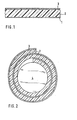
- the thin layer 1 represents the back coating of the plastic film 2, which thin layer 1 consists of a wax, wax-like material or a liquid, the character of which is similar or similar to that of molten waxes.
- the melting color in the form of layer 3 On the opposite side of the Plastic film 2 is the melting color in the form of layer 3.
- the thin back coating 1 is not yet formed. Rather, a plastic film 2, which is provided with a layer 3 of the melting color, is rolled up over a roll 4. The plastic film 2 and the layer 3 are in intimate contact, so at an elevated temperature, for. B. at temperatures of more than 40 ° C, the material contained in the layer 3 migrates to the surface of the plastic film 2 in contact with it and forms an extremely thin back coating there, which is shown in FIG. 1 as a thin layer 1.
- a plastic film in the form of an 8 ⁇ m thick polyethylene terephthalate film is coated on one side with 3 g / m 2 of a mixture of the following materials:
- a mixture of an ester wax and petrol (2.0% and 98.0%) is applied to the back in an amount of 0.05 g / m 2 .
- Such a tape can be used immediately and shows very good typeface.
- the starting point is a plastic film in the form of a polyethylene terephthalate film with a thickness of 8 ⁇ m.
- the mixture specified below is applied in an amount of 3 g / m 2 :
- an 8 ⁇ m thick polyethylene terephthalate film is used as the carrier material, which is coated with the following mixture in an amount of 3 g / m 2 :
- Such a material is rolled up according to the procedure of Example 2 and tested without storage and then after 8 hours of storage at 50 ° C. It turns out that a tape without storage is transported very poorly during the writing process and, in addition, the writing is very smeared. Even 8 hours of storage at 50 ° C does not provide any significant improvement, so there is also very poor tape transport and very heavy smearing the script ascertainable.
Landscapes
- Physics & Mathematics (AREA)
- Optics & Photonics (AREA)
- Thermal Transfer Or Thermal Recording In General (AREA)
- Impression-Transfer Materials And Handling Thereof (AREA)
- Laminated Bodies (AREA)
Abstract
Description
- Die Erfindung betrifft ein Thermofarbband, insbesondere Thermocarbonband, mit einer Kunststoffolie als Träger und einer auf einer Seite der Kunststoffolie ausgebildeten Schicht aus einer Aufschmelzfarbe.
- Diese Thermofarbbänder sind bekannt. Sie weisen auf einem folienartigen Träger, der aus Papier, Kunststoff und dgl. bestehen kann, eine Aufschmelzfarbe, insbesondere in Form einer wachsgebundenen Farbstoff- oder Rußschicht auf. Diese Aufschmelzfarbe wird bei einem derartigen übertragungsmaterial mittels eines Wärmedruckkopfes geschmolzen und auf ein Aufzeichnungspapier bzw. ein Druckpapier übertragen. Thermische Drucker bzw. Wärmedruckköpfe, die für diesen Vorgang verwendet werden, sind z. B. aus den DE-ASen 2 062 494 und 2 406 613 sowie der DE-OS 3 224 445 bekannt. Im einzelnen kann dabei z. B. wie folgt vorgegangen werden: In eine Druckwalze aus Weichgummi wird über ein Blattaufzeichnungspapier und über ein Thermofarbband der oben beschriebenen Art mittels einer Feder der Wärmedruckkopf angepreßt. Auf dem Wärmedruckkopf befindet sich ein aus beheizten Punkten bestehendes und aufzudruckendes Symbol, z. B. ein Buchstabe. Der Wärmedruckkopf entwickelt dabei Temperaturen, die im Maximalbereich bei etwa 400 °C liegen können.Die unbeschichtete Rückseite des Thermofarbbandes steht während des Druckvorganges in direktem Kontakt mit dem Wärmedruckkopf und wird mit einer Temperatur von max. etwa 400 °C belastet. Im Zeitpunkt des eigentlichen Druckvorganges beträgt die relative Geschwindigkeit zwischen dem Thermofarbband und dem Druckpapier Null. Daher haften das Druckpapier und das Thermofarbband aneinander. Durch die erwähnte Zufuhr von Wärme wird die Aufschmelzfarbe in Form des aufzudruckenden Symbols in dem Thermofarbband auf das Druckpapier übertragen.Wenn dann nachfolgend das Thermofarbband von dem Druckpapier abgelöst wird, um von einer Aufnahmespule aufgenommen zu werden, erfolgt die eigentliche Übertragung der Farbe auf das Druckpapier durch die Haftung der flüssigen Farbe auf demselben. Es hat sich jedoch gezeigt, daß das erzielte Druckbild, insbesondere bezüglich Schärfe, nicht stets den gestellten Anforderungen genügt.
- Der Erfindung lag daher die Aufgabe zugrunde, das eingangs bezeichnete Thermofarbband so weiterzubilden, daß die aufgezeigten Mängel behoben werden. Des weiteren soll die Erfindung ein besonders geeignetes Verfahren zur Herstellung derartiger Thermofarbbänder vorschlagen.
- Erfindungsgemäß wird diese Aufgabe dadurch gelöst, daß auf der Rückseite der Kunststoffolie ein organisches Material in Form einer geschlossenen Schicht aufgebracht ist, die aus einem Wachs, einem wachsartigen Material oder einer Flüssigkeit, die die Kunststoffolie benetzt, nicht fadenziehend und unter Druckbedingungen nicht zersetzbar ist, gebildet ist.
- Für die Zwecke der Erfindung kommen beliebige Kunststofffolien in Frage, die auch als Träger bei den herkömmlichen Carbonbändern von Schreibmaschinen herangezogen werden, die aber auch den erwähnten hohen Temperaturen beim kurzzeitig ablaufenden Druckvorgang standhalten und darüber hinaus bei diesen Temperaturen ohne weiteres an der beheizten Stelle die insbesondere wachsgebundene Aufschmelzfarbe freigeben. Die Kunststoffolie besteht insbesondere aus thermoplastischen Kunststoffen. Dabei stehen folgende Materialien im Vordergrund: im Stand der Technik herangezogene Polyester, insbesondere Polyethylenterephthalat, Polycarbonate, Polyamide, Polyvinylverbindungen, wie insbesondere Polyvinylchlorid, Polyvinylacetat, Polyvinylalkohol und Polyvinylpropionat, Polyethylen, Polypropylen und Polystyrol. Bei der erfindungsgemäß heranzuziehenden Kunststoffolie kann es sich auch um eine solche handeln, die aus einem ein- oder beidseitig kunststoffkaschierten Gewebe besteht. Selbstverstädnlich lassen sich für die Zwecke der Erfindung auch ähnlich konzipierte Verbundfolien einsetzen, die dem Fachmann geläufig sind.
- In Einzelfällen kann es für die Zwecke der Erfindung vorteilhaft sein, dem jeweils gewählten Kunststoffträgermaterial einen Weichmacher einzuverleiben, um eine verbesserte Flexibilität zu erzielen. Des weiteren kann auch eine die Wärmeleitfähigkeit erhöhende Substanz eingearbeitet sein. Die Stärke der oben beschriebenen Kunststofffolie wird nach den jeweiligen praktischen Erfordernissen bestimmt. In der Regel ist sie jedoch relativ dünn, z. B. 3 bis 6 µm, um die erforderlichen Wärmeübergänge optimal ablaufen zu lassen. Dieser Bereich kann aber auch unter- oder überschritten werden.
- Auf der dem Druckpapier beim Druckvorgang zugewandten Seite der Kunststoffolie des erfindungsgemäßen Thermofarbbandes befindet sich eine Schicht aus der wachsgebundenen und haftenden Aufschmelzfarbe. In diesem Zusammenhang ist der Begriff "Wachs" im Sinne der Erfindung weitestgehend zu verstehen. Ein derartiges Material soll in der Regel folgende Eigenschaften haben: bei 20 °C nicht knetbar, fest bis brüchig hart,grob- bis feinkristallin, durchscheinend bis opak, jedoch nicht glasartig: über 40 °C ohne Zersetzung schmelzbar, allerdings schon wenig oberhalb des Schmelzpunktes verhältnismäßig niedrigviskos und nicht fadenziehend. Beim Druckvorgang wird die Aufschmelzfarbe an der gewünschten Stelle von der Kunststoffolie zumindest teilweise abgelöst und auf das Aufnahmepapier übertragen. Bei dem nachfolgenden Abkühlen erstarrt die übertragene Aufschmelzfarbe schnell und bildet einen weitgehend scharfen Druck. Die in dem jeweils gewählten Wachs der Aufschmelzfarbe enthaltenen Farben bzw. Farbstoffe können insbesondere sein: Ruß, farbige Pigmente, insbesondere lichtechte Pigmente, und in Wachs lösliche Farbstoffe, insbesondere Farbstoffe mit einer guten Löslichkeit und einer hohen Lichtechtheit. Im Falle der Verwendung von Ruß wird im Rahmen der Erfindung von einem "Thermocarbonband" gesprochen.
- Das eigentliche Wesen der vorliegenden Erfindung besteht darin, daß auf der Rückseite der erwähnten Kunststofffolie ein besonderes Beschichtungsmaterial aufgebracht ist. Hierbei handelt es sich um Materialien, die verschiedenen Bedingungen genügen müssen. Diesen Bedingungen gehorcht regelmäßig ein Wachs bzw. auch wachsartiges Material. Was unter einem "Wachs" zu verstehen ist, wurde vorstehend bereits erläutert. Unter wachsartigen Materialien versteht man solche Materialien, die bezüglich der physikalischen und chemischen Eigenschaften weitgehend den Wachsen ähneln, d. h. sie sollen insbesondere fest bis brüchig hart, grob- bis feinkristallin, durchscheinend bis opak, jedoch nicht glasartig sein, über 40 °C ohne Zersetzung schmelzen, schon wenig oberhalb des Schmelzpunktes verhältnismäßig niedrigviskos und nicht fadenziehend sein. Die für die Zwecke der Erfindung ebenfalls in Frage kommenden Flüssigkeiten der vorstehend bezeichneten Eigenschaften ähneln weitgehend den geschmolzenen Wachsen, d. h. sie haben ähnliche oder gleiche Eigenschaften, wie sie bei Wachsen oberhalb des Schmelzpunktes in Erscheinung treten.
- Zu den erfindungsgemäß in Frage kommenden Materialien zur Ausbildung der Rückseitenbeschichtung der Kunststoffolie haben sich insbesondere als geeignet erwiesen: Paraffine, Silikone, Naturwachs, insbesondere Carnaubawachs, Bienenwachs, Ozokerit und Paraffinwachs, Synthetikwachs, insbesondere Säurewachse, Esterwachse, teilverseifte Esterwachse und Polyethylenwachse, Glykole bzw. Polyglykole und/oder Tenside, wie z. B. ein ethoxyliertes Nonylphenol. Die obige Auflistung ist jedoch, wie dem Fachmann erkennbar, keineswegs als erschöpfend anzusehen. Vielmehr ließe sich diese Liste beliebig fortsetzen, weil generell Materialien in Frage kommen, die insbesondere die bereits beschriebenen Anforderungen erfüllen. Darüberhinaus sollten sie bei der herrschenden Drucktemperatur geeignet sein,Resistenz zu zeigen, so daß sie keine nachteiligen Ablagerungen auf dem Thermodruckkopf bilden. Auch sollen sie sich von dem Thermofarbband selbst möglichst nicht lösen, um eine derartige nachteilige Ablagerung auszuschließen.
- Die Art, wie man auf der Rückseite der Kunststoffolie des erfindungsgemäßen Thermofarbbandes die geschilderte Schicht aufbringt, ist für den angestrebten Erfolg nicht entscheidend. So kann dies auf beliebige herkömmliche Weise durch eine Beschichtung aus der Schmelze, durch Lösungsmittelbeschichtung im Flexodruck, Kupfertiefdruck bzw. durch andere Druckverfahren, durch Bürstenauftrag oder Sprühen und dgl. erfolgen. Unter verfahrenstechnischen Gesichtspunkten heben sich jedoch aus diesen Verfahren insbesondere zwei Verfahren heraus, die vor allem auch die Ausbildung einer vorteilhaften dünnen Schicht von zweckmäßigerweise nicht mehr als 1..µm ermöglichen.
- So kann zunächst so vorgegangen werden, daß das aufzubringende Material in einem organischen Lösungsmittel gelöst, insbesondere in einem Kohlenwasserstoff, wie Benzol, Toluol, Xylol und Benzin, oder aus einer Emulsion aufgebracht wird. Dabei kann die geschlossene .Phase der Emulsion insbesondere aus Wasser oder wäßrigen Systemen bestehen. Hierbei wird die jeweilige Konzentration des dispergierten Materials im Hinblick auf die gewünschte Schichtstärke eingestellt.
- Dabei sind in der Regel Konzentrationen von 0,1 bis 2 Gew.% geeignet. Selbstverständlich können diese Werte auch unter- bzw. überschritten werden. Das Aufbringen der Lösung bzw. Emulsion erfolgt insbesondere nach den Techniken des Walzenauftrags und Flexodrucks. Anschließsend wird das Lösungsmittel, das möglichst leicht verdampfbar sein soll, durch übliche Verdampfungstechniken entfernt. Auf diese Weise bildet sich die gewünschte Beschichtung aus.
- Besonders günstig läßt sich eine etwa monomolekulare bis 1 µm starke Schicht aus dem erfindungsgemäß einzusetzenden organischen Material dadurch ausbilden, indem es ursprünglich der Aufschmelzfarbe in möglichst geringer Konzentration, z. B. in einer Konzentration von 0,5 % bis 10 % einverleibt wird und eine derartige Aufschmelzfarbe in üblicher Weise auf die Kunststoffolie des Thermofarbbandes aufgebracht wird. Ein derartig hergestelltes Band wird dann aufgerollt, wodurch jeweils die Rückseite der Kunststoffolie mit der Schicht aus der Aufschmelzfarbe in innigem Kontakt steht. Es hat sich überraschenderweise gezeigt, daß bei der Wärmebehandlung, z. B. in einem Temperaturbereich von 40 bis 60.°C während bereits einer geringen Zeitdauer, so z. B. insbeondere von 4 Stunden und mehr, bei dickeren Rollen entsprechend mehr, ein Migrationsvorgang abläuft, bei dem die der Aufschmelzfarbschicht einverleibten und vorstehend geschilderten organischen Materialien zur Oberfläche des Kunststoffolienträgers wandern. Die dabei ausgebildete Schicht ist naturgemäß sehr dünn, beispielsweise etwa in der Stärke einer molekularen Schicht, und läßt aber dennoch die gestellte Aufgabe in dem erwünschten Ausmaß lösen. Dieses Verfahren hat gegenüber anderen geeigneten Verfahren den Vorteil, daß man ohne großen technischen Aufwand extrem dünne Schichten ausbilden kann.
- Die mit der Erfindung erzielbaren Vorteile sind insbesondere darin zu sehen, daß in technisch einfacher Weise ein Thermofarbband hergestellt werden kann, das bei der Anwendung stets ein Druckbild der gewünschten Schärfe entstehen läßt. Darüber hinaus hat es sich gezeigt, daß auch ein gelegentliches Blockieren des Thermofarbbandes am Druckkopf vermieden wird.
- Nachfolgend soll die Erfindung anhand von Figuren und Beispielen näher erläutert werden.
- In den folgenden Figuren bedeuten:
- Fig. 1: einen Querschnitt eines erfindungsgemäßen Thermofarbbandes und
- Fig. 2: ein aufgerolltes Band, zunächst ohne Rückseitenbeschichtung, zur Erläuterung des erfindungsgemäßen Verfahrens, bei dem ein Migrationsvorgang genutzt wird.
- In der Fig. 1 stellt die dünne Schicht 1 die Rückseitenbeschichtung der Kunststoffolie 2 dar, wobei diese dünne Schicht 1 aus einem Wachs, wachsähnlichen Material oder aus einer Flüssigkeit besteht, deren Charakter dem von geschmolzenen Wachsen gleicht bzw. ähnelt.Auf der entgegengesetzten Seite der Kunststoffolie 2 befindet sich die Aufschmelzfarbe in Form der Schicht 3.
- Bei der Fig. 2 ist zunächst die dünne Rückseitenbeschichtung 1 noch nicht ausgebildet. Vielmehr ist dort eine Kunststoffolie 2, die mit einer Schicht 3 der Aufschmelzfarbe versehen ist, über eine Rolle 4 aufgerollt. Die Kunststoffolie 2 und die Schicht 3 befinden sich in innigem Kontakt, damit bei angehobener Temperatur, z. B. bei Temperaturen von mehr als 40 °C, in der Schicht 3 enthaltenes Material auf die Oberfläche der damit in Kontakt stehenden Kunststoffolie 2 wandert und dort eine äußerst dünne Rückseitenbeschichtung ausbildet, die in der Fig. 1 als dünne Schicht 1 dargestellt ist.
- Es wird eine Kunststoffolie in Form einer 8 um starken Polyethylenterephthalatfolie auf der einen Seite mit 3 g/m2 einer Mischung folgender Materialien beschichtet:

- Auf der Rückseite wird ein Gemisch aus einem Esterwachs und Benzin (2,0 % bzw. 98,0 %) in einer Menge von 0,05 g/m2 aufgetragen. Ein derartiges Band ist unmittelbar einsetzbar und zeigt sehr gute Schriftschärfe.
- Ausgegangen wird von einer Kunststoffolie in Form einer Polyethylenterephthalatfolie einer Stärke von 8 µm. In einer Menge von 3 g/m2 wird das nachfolgend näher bezeichnete Gemisch aufgebracht:

- Eine derartig hergestellte Folie mit lediglich einseitiger Beschichtung wird zu einer Spule aufgerollte darauf bei 50 °C gelagert, um den Migrationsvorgang ablaufen zu lassen. Dabei hat es sich gezeigt, daß ein Band ohne Lagerung schlecht beim Schreibvorgang transportiert wird und die Schrift beim Einsatz des Bandes sehr stark verschmiert. Nach einer Lagerung von 2 Stunden bei 50 °C zeigt es sich, daß das Band noch ungleichmäßig transportiert wird und die Schrift auch noch stellenweise verschmiert. Eine befriedigende Schriftstärke und ein gleichmäßiger Bandtransport ist dann feststellbar, wenn die Lagerung 4 Stunden lang erfolgt. Besonders gute Ergebnisse werden erzielt, wenn eine Lagerung von etwa 8 Stunden erfolgt, wobei eine besonders gute Schriftstärke feststellbar ist.
- Hier wird ebenfalls eine 8 µm starke Polyethylenterephthalatfolie als Trägermaterial verwendet, das mit dem folgenden Gemisch in einer Menge von 3 g/m2 beschichtet wird:

Claims (7)
Priority Applications (1)
| Application Number | Priority Date | Filing Date | Title |
|---|---|---|---|
| AT84106648T ATE31049T1 (de) | 1983-08-11 | 1984-06-09 | Thermofarbband sowie verfahren zu dessen herstellung. |
Applications Claiming Priority (2)
| Application Number | Priority Date | Filing Date | Title |
|---|---|---|---|
| DE3328990 | 1983-08-11 | ||
| DE3328990A DE3328990C2 (de) | 1983-08-11 | 1983-08-11 | Thermofarbband sowie Verfahren zu dessen Herstellung |
Publications (4)
| Publication Number | Publication Date |
|---|---|
| EP0133638A2 true EP0133638A2 (de) | 1985-03-06 |
| EP0133638A3 EP0133638A3 (en) | 1985-07-24 |
| EP0133638B1 EP0133638B1 (de) | 1987-11-25 |
| EP0133638B2 EP0133638B2 (de) | 1991-08-28 |
Family
ID=6206299
Family Applications (1)
| Application Number | Title | Priority Date | Filing Date |
|---|---|---|---|
| EP84106648A Expired - Lifetime EP0133638B2 (de) | 1983-08-11 | 1984-06-09 | Thermofarbband sowie Verfahren zu dessen Herstellung |
Country Status (5)
| Country | Link |
|---|---|
| US (2) | US4592945A (de) |
| EP (1) | EP0133638B2 (de) |
| JP (1) | JPS6056583A (de) |
| AT (1) | ATE31049T1 (de) |
| DE (2) | DE3328990C2 (de) |
Cited By (1)
| Publication number | Priority date | Publication date | Assignee | Title |
|---|---|---|---|---|
| WO2003037644A2 (de) | 2001-10-29 | 2003-05-08 | Emtec Magnetics Gmbh | Beschichtung eines thermotransfer- und/oder thermosublimationsproduktes, verfahren zu dessen herstellung sowie dessen verwendung |
Families Citing this family (18)
| Publication number | Priority date | Publication date | Assignee | Title |
|---|---|---|---|---|
| DE3409936C1 (de) * | 1984-03-17 | 1985-12-05 | Pelikan Ag, 3000 Hannover | Farbband |
| US4724025A (en) * | 1984-08-13 | 1988-02-09 | Olympus Optical Co., Ltd. | Transfer coating method |
| JPS61211056A (ja) * | 1985-03-15 | 1986-09-19 | General Kk | サ−マルプリント方法 |
| DE3520308A1 (de) * | 1985-06-07 | 1986-12-11 | Pelikan Ag, 3000 Hannover | Verfahren zur herstellung eines thermofarbbandes fuer den thermotransferdruck und das danach erhaeltliche thermofarbband |
| DE3522801C1 (de) * | 1985-06-26 | 1986-10-23 | Pelikan Ag, 3000 Hannover | Thermofarbband sowie ein Verfahren zu dessen Herstellung |
| DE3635114C1 (de) * | 1986-10-15 | 1988-07-14 | Caribonum Ltd | UEberlappend ueberschreibbares Farbband sowie seine Verwendung in endlos gestopften Kassetten |
| DE3635141C1 (de) * | 1986-10-15 | 1988-03-03 | Pelikan Ag | Thermocarbonband mit einer kunststoffgebundenen Aufschmelzfarbe sowie ein Verfahren zur Herstellung dieses Bandes |
| US4925324A (en) * | 1987-10-02 | 1990-05-15 | Alps Electric Co., Ltd. | Color ink ribbon for thermal printer |
| US5318938A (en) * | 1989-05-05 | 1994-06-07 | Minnesota Mining And Manufacturing Company | Thermographic elements |
| US4916112A (en) * | 1989-06-30 | 1990-04-10 | Eastman Kodak Company | Slipping layer containing particulate ester wax for dye-donor element used in thermal dye transfer |
| DE19548033A1 (de) | 1995-12-21 | 1997-07-03 | Pelikan Produktions Ag | Thermotransferband |
| DE19820769B4 (de) * | 1998-05-08 | 2004-02-05 | Pelikan Produktions Ag | Thermotransferband |
| US6358597B1 (en) | 1997-08-07 | 2002-03-19 | Pelikan Produktions Ag | Thermo-transfer ribbon |
| US6138569A (en) * | 1997-10-03 | 2000-10-31 | General Credit Forms, Inc. | Single-ply imprintable receipt and method of imprinting a receipt |
| DE19820779A1 (de) * | 1998-05-08 | 1999-11-11 | Pelikan Produktions Ag Egg | Thermotransferband |
| DE19820778C2 (de) * | 1998-05-08 | 2003-02-20 | Pelikan Produktions Ag Egg | Thermotransferband |
| DE102007027784B4 (de) * | 2007-06-16 | 2010-06-02 | Bischof + Klein Gmbh & Co. Kg | Verpackungsbehälter |
| JP6170110B2 (ja) | 2015-10-15 | 2017-07-26 | Necプラットフォームズ株式会社 | 冷却装置および冷媒中継装置 |
Family Cites Families (21)
| Publication number | Priority date | Publication date | Assignee | Title |
|---|---|---|---|---|
| US1375866A (en) * | 1916-04-05 | 1921-04-26 | Eastman Kodak Co | Stencil-sheet and process for making it |
| US2322367A (en) * | 1941-06-03 | 1943-06-22 | Interchem Corp | Carbon paper |
| US2628929A (en) * | 1949-07-15 | 1953-02-17 | Minnesota Mining & Mfg | Method and apparatus for transferring a magnetic sound track to movie film |
| DE1742058U (de) * | 1957-01-18 | 1957-03-28 | Pelikan Werke Wagner Guenther | Karbonband bzw. spirit-karbon-band. |
| US3035936A (en) * | 1960-08-22 | 1962-05-22 | Columbia Ribbon & Carbon | Method of rendering transfer sheets resistant to curling and slipping and resultant article |
| US3131080A (en) * | 1960-11-09 | 1964-04-28 | Robert B Russell | Thermographic transfer sheet comprising selective radiation filtering means |
| CA929041A (en) * | 1967-09-15 | 1973-06-26 | The Robinson Waxed Paper Company Limited | Processing of web material |
| US3628979A (en) * | 1968-06-20 | 1971-12-21 | Columbia Ribbon & Carbon | Transfer elements and method of making same |
| US3630802A (en) * | 1970-07-13 | 1971-12-28 | Theodore J Dettling | Method and apparatus for producing a coated substrate and a laminated product |
| DE2062494C3 (de) * | 1970-12-18 | 1975-04-30 | Triumph Werke Nuernberg Ag, 8500 Nuernberg | Wärmedruckkopf |
| US3857720A (en) * | 1973-02-08 | 1974-12-31 | Ncr Co | Polysiloxane coated transfer base |
| JPS49106731A (de) * | 1973-02-12 | 1974-10-09 | ||
| JPS5813359B2 (ja) * | 1978-07-03 | 1983-03-12 | 富士化学紙工業株式会社 | 感熱転写材 |
| DE2931616A1 (de) * | 1978-08-04 | 1980-02-14 | Bando Chemical Ind | Struktur einer druckenden oder druckfarbe uebertragenden oberflaechenschicht eines druckwerkzeugs, -geraets, -apparats oder einer druckvorrichtung |
| US4320170A (en) * | 1980-12-08 | 1982-03-16 | International Business Machines Corporation | Polyurethane ribbon for non-impact printing |
| JPS57129789A (en) * | 1981-02-05 | 1982-08-11 | Fuji Kagakushi Kogyo Co Ltd | Heat sensitive transferring material |
| US4400100A (en) * | 1981-03-02 | 1983-08-23 | International Business Machines Corp. | Four layered ribbon for electrothermal printing |
| JPS585280A (ja) * | 1981-07-03 | 1983-01-12 | Canon Inc | 画像記録方法 |
| IT1145104B (it) * | 1981-09-21 | 1986-11-05 | Olivetti & Co Spa | Elemento inchiostrato termosensibile per stampanti senza impatto di tipo termico |
| JPS58171992A (ja) * | 1982-04-01 | 1983-10-08 | Dainippon Printing Co Ltd | 感熱転写シ−ト |
| JPS59148697A (ja) * | 1983-02-15 | 1984-08-25 | Mitsubishi Paper Mills Ltd | 熱転写記録材 |
-
1983
- 1983-08-11 DE DE3328990A patent/DE3328990C2/de not_active Expired
-
1984
- 1984-06-09 EP EP84106648A patent/EP0133638B2/de not_active Expired - Lifetime
- 1984-06-09 AT AT84106648T patent/ATE31049T1/de not_active IP Right Cessation
- 1984-06-09 DE DE8484106648T patent/DE3467736D1/de not_active Expired
- 1984-07-30 US US06/635,818 patent/US4592945A/en not_active Expired - Lifetime
- 1984-08-10 JP JP59166641A patent/JPS6056583A/ja active Pending
-
1985
- 1985-10-03 US US06/783,843 patent/US4675063A/en not_active Expired - Lifetime
Cited By (2)
| Publication number | Priority date | Publication date | Assignee | Title |
|---|---|---|---|---|
| WO2003037644A2 (de) | 2001-10-29 | 2003-05-08 | Emtec Magnetics Gmbh | Beschichtung eines thermotransfer- und/oder thermosublimationsproduktes, verfahren zu dessen herstellung sowie dessen verwendung |
| DE10152849A1 (de) * | 2001-10-29 | 2003-05-28 | Emtec Magnetics Gmbh | Beschichtung eines Thermotransfer- und/oder Thermosublimationsproduktes, Verfahren zu dessen Herstellung sowie dessen Verwendung |
Also Published As
| Publication number | Publication date |
|---|---|
| DE3328990C2 (de) | 1985-12-12 |
| EP0133638B2 (de) | 1991-08-28 |
| DE3328990A1 (de) | 1985-02-28 |
| JPS6056583A (ja) | 1985-04-02 |
| EP0133638A3 (en) | 1985-07-24 |
| DE3467736D1 (en) | 1988-01-07 |
| EP0133638B1 (de) | 1987-11-25 |
| US4675063A (en) | 1987-06-23 |
| US4592945A (en) | 1986-06-03 |
| ATE31049T1 (de) | 1987-12-15 |
Similar Documents
| Publication | Publication Date | Title |
|---|---|---|
| EP0133638B1 (de) | Thermofarbband sowie Verfahren zu dessen Herstellung | |
| DE2560409C2 (de) | Thermisches Druckfarbenübertragungselement für elektrothermische Drucker | |
| EP0206036B1 (de) | Thermofarbband sowie ein Verfahren zu dessen Herstellung | |
| DE69131994T2 (de) | Thermisches Übertragungsdruckverfahren und Druckmaterialien, die bei diesem Verfahren verwendet werden | |
| DE69809146T2 (de) | Thermisches Übertragungsverfahren mit der Verwendung eines Zwischenübertragungsaufzeichnungsmediums und Druckmaterialsatz | |
| DE69402672T2 (de) | Trennmittel für thermisches Farbstoffübertragungsempfangselement | |
| DE3822163C2 (de) | ||
| DE3520308A1 (de) | Verfahren zur herstellung eines thermofarbbandes fuer den thermotransferdruck und das danach erhaeltliche thermofarbband | |
| DE3728075C2 (de) | ||
| DE69202693T2 (de) | Farbstoffgebende Elementen für thermische Farbstoffübertragung. | |
| DE3728076C2 (de) | ||
| EP0810924B1 (de) | Thermotransferband | |
| EP0785086A1 (de) | Thermotransferband | |
| DE1796221A1 (de) | Druckempfindliches Farbblatt und Verfahren zu seiner Herstellung | |
| DE69800306T2 (de) | Thermisches Übertragungsblatt und Herstellungsverfahren | |
| DE1571910C3 (de) | Druckempfindliches Farbübertragungsblatt, -band od.dgl. und Verfahren zu seiner Herstellung | |
| DE2117214C3 (de) | Druckempfindliches Farbblatt, -band o.dgl | |
| EP0182011A2 (de) | Verfahren, Vorrichtung und Farbstift zum Regenerieren eines Thermofarbbandes | |
| DE3816636C2 (de) | ||
| EP0955181B1 (de) | Thermotransferband mit einer Trennschicht | |
| EP0352525A2 (de) | Thermofarbband sowie ein Verfahren zu dessen Herstellung | |
| EP0955182B1 (de) | Thermotransferband | |
| DE3903259C1 (de) | ||
| DE2332527C2 (de) | Druckempfindliche Bilderzeugungsmaterialien | |
| DE1166796B (de) | Verfahren zur Herstellung von Blaettern fuer Durchschriften ohne Kohlepapier |
Legal Events
| Date | Code | Title | Description |
|---|---|---|---|
| PUAI | Public reference made under article 153(3) epc to a published international application that has entered the european phase |
Free format text: ORIGINAL CODE: 0009012 |
|
| 17P | Request for examination filed |
Effective date: 19840609 |
|
| AK | Designated contracting states |
Designated state(s): AT BE CH DE FR GB IT LI LU NL SE |
|
| PUAL | Search report despatched |
Free format text: ORIGINAL CODE: 0009013 |
|
| RHK1 | Main classification (correction) |
Ipc: B41J 31/05 |
|
| AK | Designated contracting states |
Designated state(s): AT BE CH DE FR GB IT LI LU NL SE |
|
| 17Q | First examination report despatched |
Effective date: 19860718 |
|
| GRAA | (expected) grant |
Free format text: ORIGINAL CODE: 0009210 |
|
| AK | Designated contracting states |
Kind code of ref document: B1 Designated state(s): AT BE CH DE FR GB IT LI LU NL SE |
|
| REF | Corresponds to: |
Ref document number: 31049 Country of ref document: AT Date of ref document: 19871215 Kind code of ref document: T |
|
| REF | Corresponds to: |
Ref document number: 3467736 Country of ref document: DE Date of ref document: 19880107 |
|
| ET | Fr: translation filed | ||
| ITF | It: translation for a ep patent filed | ||
| GBT | Gb: translation of ep patent filed (gb section 77(6)(a)/1977) | ||
| PLBI | Opposition filed |
Free format text: ORIGINAL CODE: 0009260 |
|
| 26 | Opposition filed |
Opponent name: FUJI KAGAKUSHI KOGYO CO., LTD. Effective date: 19880819 |
|
| NLR1 | Nl: opposition has been filed with the epo |
Opponent name: FUJI KAGAKUSHI KOGYO CO., LTD. |
|
| ITTA | It: last paid annual fee | ||
| PUAH | Patent maintained in amended form |
Free format text: ORIGINAL CODE: 0009272 |
|
| STAA | Information on the status of an ep patent application or granted ep patent |
Free format text: STATUS: PATENT MAINTAINED AS AMENDED |
|
| 27A | Patent maintained in amended form |
Effective date: 19910828 |
|
| AK | Designated contracting states |
Kind code of ref document: B2 Designated state(s): AT BE CH DE FR GB IT LI LU NL SE |
|
| NLR2 | Nl: decision of opposition | ||
| ITF | It: translation for a ep patent filed | ||
| ET3 | Fr: translation filed ** decision concerning opposition | ||
| NLR3 | Nl: receipt of modified translations in the netherlands language after an opposition procedure | ||
| GBA | Gb: translation amended (gb section 77(6)(a)/1977) | ||
| REG | Reference to a national code |
Ref country code: CH Ref legal event code: PFA Free format text: PELIKAN GMBH |
|
| ITPR | It: changes in ownership of a european patent |
Owner name: TRASFORMAZIONE SOCIETARIA;PELIKAN GMBH |
|
| EPTA | Lu: last paid annual fee | ||
| NLS | Nl: assignments of ep-patents |
Owner name: PELIKAN GMBH TE HANNOVER, BONDSREPUBLIEK DUITSLAND |
|
| REG | Reference to a national code |
Ref country code: FR Ref legal event code: CJ |
|
| EAL | Se: european patent in force in sweden |
Ref document number: 84106648.3 |
|
| REG | Reference to a national code |
Ref country code: CH Ref legal event code: PUE Owner name: PELIKAN GMBH TRANSFER- PELIKAN PRODUKTIONS AG |
|
| REG | Reference to a national code |
Ref country code: FR Ref legal event code: TP |
|
| NLS | Nl: assignments of ep-patents |
Owner name: PELIKAN PRODUKTIONS AG |
|
| REG | Reference to a national code |
Ref country code: GB Ref legal event code: 732E |
|
| REG | Reference to a national code |
Ref country code: GB Ref legal event code: 732E |
|
| PGFP | Annual fee paid to national office [announced via postgrant information from national office to epo] |
Ref country code: SE Payment date: 20000417 Year of fee payment: 17 |
|
| PGFP | Annual fee paid to national office [announced via postgrant information from national office to epo] |
Ref country code: LU Payment date: 20000609 Year of fee payment: 17 |
|
| PGFP | Annual fee paid to national office [announced via postgrant information from national office to epo] |
Ref country code: AT Payment date: 20000623 Year of fee payment: 17 |
|
| PGFP | Annual fee paid to national office [announced via postgrant information from national office to epo] |
Ref country code: NL Payment date: 20000630 Year of fee payment: 17 |
|
| PGFP | Annual fee paid to national office [announced via postgrant information from national office to epo] |
Ref country code: BE Payment date: 20001026 Year of fee payment: 17 |
|
| PG25 | Lapsed in a contracting state [announced via postgrant information from national office to epo] |
Ref country code: LU Free format text: LAPSE BECAUSE OF NON-PAYMENT OF DUE FEES Effective date: 20010609 Ref country code: AT Free format text: LAPSE BECAUSE OF NON-PAYMENT OF DUE FEES Effective date: 20010609 |
|
| PG25 | Lapsed in a contracting state [announced via postgrant information from national office to epo] |
Ref country code: SE Free format text: LAPSE BECAUSE OF NON-PAYMENT OF DUE FEES Effective date: 20010610 |
|
| PG25 | Lapsed in a contracting state [announced via postgrant information from national office to epo] |
Ref country code: BE Free format text: LAPSE BECAUSE OF NON-PAYMENT OF DUE FEES Effective date: 20010630 |
|
| BERE | Be: lapsed |
Owner name: PELIKAN PRODUKTIONS A.G. Effective date: 20010630 |
|
| PG25 | Lapsed in a contracting state [announced via postgrant information from national office to epo] |
Ref country code: NL Free format text: LAPSE BECAUSE OF NON-PAYMENT OF DUE FEES Effective date: 20020101 |
|
| REG | Reference to a national code |
Ref country code: GB Ref legal event code: IF02 |
|
| EUG | Se: european patent has lapsed |
Ref document number: 84106648.3 |
|
| NLV4 | Nl: lapsed or anulled due to non-payment of the annual fee |
Effective date: 20020101 |
|
| REG | Reference to a national code |
Ref country code: CH Ref legal event code: PVP |
|
| PGFP | Annual fee paid to national office [announced via postgrant information from national office to epo] |
Ref country code: GB Payment date: 20030516 Year of fee payment: 20 |
|
| PGFP | Annual fee paid to national office [announced via postgrant information from national office to epo] |
Ref country code: FR Payment date: 20030618 Year of fee payment: 20 |
|
| PGFP | Annual fee paid to national office [announced via postgrant information from national office to epo] |
Ref country code: CH Payment date: 20030704 Year of fee payment: 20 |
|
| PGFP | Annual fee paid to national office [announced via postgrant information from national office to epo] |
Ref country code: DE Payment date: 20030901 Year of fee payment: 20 |
|
| PG25 | Lapsed in a contracting state [announced via postgrant information from national office to epo] |
Ref country code: LI Free format text: LAPSE BECAUSE OF EXPIRATION OF PROTECTION Effective date: 20040608 Ref country code: GB Free format text: LAPSE BECAUSE OF EXPIRATION OF PROTECTION Effective date: 20040608 Ref country code: CH Free format text: LAPSE BECAUSE OF EXPIRATION OF PROTECTION Effective date: 20040608 |
|
| REG | Reference to a national code |
Ref country code: GB Ref legal event code: PE20 |
|
| REG | Reference to a national code |
Ref country code: CH Ref legal event code: PL |