EP0133755A2 - Leicht zu wartendes Kugelventil für extreme Bedingungen - Google Patents
Leicht zu wartendes Kugelventil für extreme Bedingungen Download PDFInfo
- Publication number
- EP0133755A2 EP0133755A2 EP84304609A EP84304609A EP0133755A2 EP 0133755 A2 EP0133755 A2 EP 0133755A2 EP 84304609 A EP84304609 A EP 84304609A EP 84304609 A EP84304609 A EP 84304609A EP 0133755 A2 EP0133755 A2 EP 0133755A2
- Authority
- EP
- European Patent Office
- Prior art keywords
- bonnet
- seat
- valve
- valve body
- valve assembly
- Prior art date
- Legal status (The legal status is an assumption and is not a legal conclusion. Google has not performed a legal analysis and makes no representation as to the accuracy of the status listed.)
- Withdrawn
Links
Images


Classifications
-
- F—MECHANICAL ENGINEERING; LIGHTING; HEATING; WEAPONS; BLASTING
- F16—ENGINEERING ELEMENTS AND UNITS; GENERAL MEASURES FOR PRODUCING AND MAINTAINING EFFECTIVE FUNCTIONING OF MACHINES OR INSTALLATIONS; THERMAL INSULATION IN GENERAL
- F16K—VALVES; TAPS; COCKS; ACTUATING-FLOATS; DEVICES FOR VENTING OR AERATING
- F16K27/00—Construction of housing; Use of materials therefor
- F16K27/06—Construction of housing; Use of materials therefor of taps or cocks
- F16K27/067—Construction of housing; Use of materials therefor of taps or cocks with spherical plugs
-
- F—MECHANICAL ENGINEERING; LIGHTING; HEATING; WEAPONS; BLASTING
- F16—ENGINEERING ELEMENTS AND UNITS; GENERAL MEASURES FOR PRODUCING AND MAINTAINING EFFECTIVE FUNCTIONING OF MACHINES OR INSTALLATIONS; THERMAL INSULATION IN GENERAL
- F16K—VALVES; TAPS; COCKS; ACTUATING-FLOATS; DEVICES FOR VENTING OR AERATING
- F16K5/00—Plug valves; Taps or cocks comprising only cut-off apparatus having at least one of the sealing faces shaped as a more or less complete surface of a solid of revolution, the opening and closing movement being predominantly rotary
- F16K5/06—Plug valves; Taps or cocks comprising only cut-off apparatus having at least one of the sealing faces shaped as a more or less complete surface of a solid of revolution, the opening and closing movement being predominantly rotary with plugs having spherical surfaces; Packings therefor
- F16K5/0626—Easy mounting or dismounting means
- F16K5/0636—Easy mounting or dismounting means the spherical plug being insertable from the top of the housing
-
- F—MECHANICAL ENGINEERING; LIGHTING; HEATING; WEAPONS; BLASTING
- F16—ENGINEERING ELEMENTS AND UNITS; GENERAL MEASURES FOR PRODUCING AND MAINTAINING EFFECTIVE FUNCTIONING OF MACHINES OR INSTALLATIONS; THERMAL INSULATION IN GENERAL
- F16K—VALVES; TAPS; COCKS; ACTUATING-FLOATS; DEVICES FOR VENTING OR AERATING
- F16K5/00—Plug valves; Taps or cocks comprising only cut-off apparatus having at least one of the sealing faces shaped as a more or less complete surface of a solid of revolution, the opening and closing movement being predominantly rotary
- F16K5/08—Details
- F16K5/14—Special arrangements for separating the sealing faces or for pressing them together
- F16K5/20—Special arrangements for separating the sealing faces or for pressing them together for plugs with spherical surfaces
- F16K5/201—Special arrangements for separating the sealing faces or for pressing them together for plugs with spherical surfaces with the housing or parts of the housing mechanically pressing the seal against the plug
- F16K5/202—Special arrangements for separating the sealing faces or for pressing them together for plugs with spherical surfaces with the housing or parts of the housing mechanically pressing the seal against the plug with conical surfaces
-
- Y—GENERAL TAGGING OF NEW TECHNOLOGICAL DEVELOPMENTS; GENERAL TAGGING OF CROSS-SECTIONAL TECHNOLOGIES SPANNING OVER SEVERAL SECTIONS OF THE IPC; TECHNICAL SUBJECTS COVERED BY FORMER USPC CROSS-REFERENCE ART COLLECTIONS [XRACs] AND DIGESTS
- Y10—TECHNICAL SUBJECTS COVERED BY FORMER USPC
- Y10T—TECHNICAL SUBJECTS COVERED BY FORMER US CLASSIFICATION
- Y10T137/00—Fluid handling
- Y10T137/7504—Removable valve head and seat unit
- Y10T137/7668—Retained by bonnet or closure
Definitions
- the invention relates to a ball valve assembly wherein the entire valve internals can be removed easily for service even under extreme environment.
- Valves in remote locations or in environments where human access is limited have been extremely difficult to maintain. Examples of such locations include the ocean floor and arctic areas.
- Ball valves are commonly used in pipelines because they provide a through conduit. However, they are particularly difficult to disassemble and reassemble when positioned, for example, on the ocean floor. Typically, such a valve would require a diver to remove the bonnet attached to the housing, disconnect the internal elements such as seats, remove the disc from the valve, and thereafter remove other internals. Each of these steps require tool manipulation, crane manipulation, and complex communications.
- U.S. Patent No. 3,891,183 is an example of a ball valve which provides successful flow regulation and is assembled and disassembled in a well-known manner.
- the invention provides a ball valve assembly including a housing, a valve member within the housing, a bonnet secured to the housing, and a valve seating assembly and other internal members secured to the bonnet.
- the valve member is preferably a double-trunnion ball.
- a tapered or wedge-shaped seat retainer assembly is bolted to the ponnet.
- a valve seat is maintained in sealing engagement dith a ball-shaped valve member.
- a valve assembly 10 which allows relatively easy maintenance even under extreme environments.
- the assembly 10 includes a valve body 12, a bonnet 14 which may be bolted to the valve body, a seat retainer assembly 16 removably secured to the bonnet 14, and a Valve member 18.
- valve body 12 The bottom of the valve body includes a cylindrical chamber 28 for rotatably receiving a lower trunnion of the valve member 18.
- the bonnet 14 includes a substantially rectangular or square plate 30 having a plurality of holes 32 about its perimeter for receiving bolts 34. When the bonnet is mounted to thevalve body 12, holes 26 and 32 will be aligned. A central opening is provided within plate 30 through which an upper trunnion of the valve member 18 extends. A circular plate 36 is bolted (with bolts 34') to the top surface of the bonnet for maintaining one or more sealing members in position between the upper trunnion and the bonnet. These members may include a plurality of 0-rings mounted within polyurethane carriers. Since the trunnion and bonnet maybe made from different material, proper sealing may be necessary to prevent electrolysis. These sealing members are not illustrated in the drawings.
- a pair of wedge-shaped seat retaining assemblies 16 are bolted to the bonnet 14.
- Each retainer includes a substantially circular body portion 16' when viewer from the front or rear.
- a pair of ears 16" project from the top thereof and provide accessible surfaces through which bolts 37 may be applied for attaching the retainers to the bonnet.
- the seat retaining assemblies are mounted in opposed relation to each other and present inclined exterior faces 38 which make flush contact with at least a portion of the inner faces 24 of the valve body 12.
- Each has a central opening aligned with ports 20.
- a bottom support plate 40 is bolted to the lower surfaces of these assemblies for alignment purposes. It includes a central opening through which a trunnion may pass.
- the valve member 18 is a double-trunnion ball having a passage 42 extending therethrough. It includes a lower trunnion 44, an integral upper trunnion 46, and the ball 48.
- the upper trunnion 46 includes a longitudinal slot 50 which may be used for turning the ball between open and closed positions.
- a threaded hole 52 extending axially from the top surface of the upper trunnion allows the attachment of an eye bolt 54.
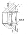
- the valve seating assembly is best shown in Figs. 3 and 4.
- a pair of slidable polyurethane seat retainers 56, 58 are resiliently urged in opposite directions by Belleville washers 60.
- a spacer 62 extends between the retainers 56, 58 from.a supporting member 64 which adjoins the outer surfaces thereof.
- the bottom support plate 40 is bolted to the supporting member 64 by bolts 66.
- 0-rings 68, 70 provide seals between one retainer 56 and the ball 48, the other retainer 58 and the seat ring defined by face 24, and the retainers and supporting member 64.
- the 0-ring 68 between the retainer 58 and face 24 is compressed by the downward force provided by the bonnet when bolted up.
- the valve assembly functions as a well-operating ball valve during use.
- An actuating mechanism (not shown) is connected to the upper trunnion 46 for turning the ball 48 so that the axis of passage 42 is aligned with or perpendicular to the axes of ports 20.
- the eye bolt 54 is secured to the upper trunnion 46 of the valve member 18 and the bolts 34 securing the bonnet 14 to the valve body 12 are removed.
- a cable secured to the eye bolt may then be used for lifting the entire valve mechanism, including the bonnet 14, seat retainer assembly 16, valve member 18, and seating assembly 56-70 from the valve body 12.
- a crane may be employed for raising these parts in one piece from the ocean floor.
- the support plate 40 is removed and the seat retainer assemblies 16 unbolted from the bonnet to gain access to the valve internals.
- the structure is reassembled and inserted as a unit into the valve body 12.
- an inventory of replacement valve structures could be maintained so that damaged valvescould be immediately replaced. The removed valvecould then be repaired when convenient.
- a preferred valve assembly comprises a :
- the assembly may include a plate removably secured to the seat retaining assemblies in opposed relation to the bonnet; a trunnion of the ball member may extend through the plate.
- Each of the seat retaining assemblies may include a body portion having a passage therethrough and a pair of projections defining an upper portion thereof, said projections being bolted to said bonnet.
Landscapes
- Engineering & Computer Science (AREA)
- General Engineering & Computer Science (AREA)
- Mechanical Engineering (AREA)
- Taps Or Cocks (AREA)
- Valve Housings (AREA)
- Fuel-Injection Apparatus (AREA)
- External Artificial Organs (AREA)
- Temperature-Responsive Valves (AREA)
Applications Claiming Priority (2)
| Application Number | Priority Date | Filing Date | Title |
|---|---|---|---|
| US06/511,365 US4562860A (en) | 1983-07-06 | 1983-07-06 | Ball valve having easy maintenance features for extreme environments |
| US511365 | 1983-07-06 |
Publications (2)
| Publication Number | Publication Date |
|---|---|
| EP0133755A2 true EP0133755A2 (de) | 1985-03-06 |
| EP0133755A3 EP0133755A3 (de) | 1986-03-19 |
Family
ID=24034578
Family Applications (1)
| Application Number | Title | Priority Date | Filing Date |
|---|---|---|---|
| EP84304609A Withdrawn EP0133755A3 (de) | 1983-07-06 | 1984-07-05 | Leicht zu wartendes Kugelventil für extreme Bedingungen |
Country Status (3)
| Country | Link |
|---|---|
| US (1) | US4562860A (de) |
| EP (1) | EP0133755A3 (de) |
| NO (1) | NO842735L (de) |
Cited By (7)
| Publication number | Priority date | Publication date | Assignee | Title |
|---|---|---|---|---|
| GB2177781A (en) * | 1985-06-07 | 1987-01-28 | Wiederaufarbeitung Von Kernbre | A remote control and remote handling accessory, especially for the hot zone of radioactive plants |
| GB2186952A (en) * | 1986-02-14 | 1987-08-26 | Hattersley Heaton Ltd | A ball valve |
| AU579381B2 (en) * | 1984-07-09 | 1988-11-24 | Nippon Ball Valve Co., Ltd. | Top entry ball valve and a clamp therefor |
| EP0303453A1 (de) * | 1987-08-11 | 1989-02-15 | T K Valve Limited | Kugelhähne für Pipe-lines |
| EP0360320A1 (de) * | 1988-09-07 | 1990-03-28 | Metallgesellschaft Ag | Einrichtung zur Fernmontage eines Einbauteils |
| GB2281924A (en) * | 1992-06-29 | 1995-03-22 | M & M Supply Company | A valve |
| KR101559747B1 (ko) | 2013-04-02 | 2015-10-14 | 주식회사 시퍼스 파이프 라인 | 고온 고압용 회전형 밸브 |
Families Citing this family (27)
| Publication number | Priority date | Publication date | Assignee | Title |
|---|---|---|---|---|
| NO166200C (no) * | 1989-02-10 | 1991-06-12 | Norske Stats Oljeselskap | Anordning ved dreieventil. |
| US5562116A (en) | 1995-02-06 | 1996-10-08 | Henwood; Gerard S. | Angle entry rotary valve |
| US6263901B1 (en) * | 1999-05-26 | 2001-07-24 | The Toro Company | Self cleaning irrigation valve with offset manual on actuator, body/bonnet alignment, and captured screws |
| US6497245B1 (en) * | 1999-10-13 | 2002-12-24 | Denso Corporation | Intake air controller for internal combustion engine and manufacturing the same |
| US6311721B1 (en) * | 2000-10-06 | 2001-11-06 | William Aaron | Residential drain line stop valve |
| US7434593B2 (en) * | 2002-10-23 | 2008-10-14 | Zurn Industries, Llc | Double check valve assembly |
| DE602004029898D1 (de) | 2003-07-01 | 2010-12-16 | Fimcim Spa | Leicht zu wartendes und zu reparierendes, inspizierbares kugelventil |
| US6983759B2 (en) * | 2003-07-31 | 2006-01-10 | Occlude | Valve and method for repairing a valve under pressure |
| US7021325B2 (en) * | 2004-01-08 | 2006-04-04 | Occlude | Valve assembly and method for hot tapping a line |
| US7784483B2 (en) * | 2005-01-21 | 2010-08-31 | Zurn Industries, Llc | Backflow preventer |
| NO322524B1 (no) * | 2005-03-31 | 2006-10-16 | Framo Eng As | Manifold |
| DE102005028198A1 (de) * | 2005-06-17 | 2006-12-21 | Linde Ag | Absperrarmatur |
| US9464726B2 (en) | 2006-05-30 | 2016-10-11 | Metso Flow Control Oy | Shut-off device for pipelines |
| US20080099712A1 (en) * | 2006-10-25 | 2008-05-01 | Honeywell International Inc. | Cartridge ball valve |
| US9488992B2 (en) * | 2008-10-16 | 2016-11-08 | Honeywell International Inc. | Wall module configuration tool |
| US8201574B2 (en) * | 2009-12-11 | 2012-06-19 | Virgo Engineers, Inc. | Bi-directional sealing ball valve |
| US8538588B2 (en) | 2011-02-28 | 2013-09-17 | Honeywell International Inc. | Method and apparatus for configuring scheduling on a wall module |
| GB201218764D0 (en) * | 2012-10-18 | 2012-12-05 | Airbus Operations Ltd | Fluid flow control valve and actuator |
| WO2014182664A1 (en) * | 2013-05-07 | 2014-11-13 | Victaulic Company | Valve with removable seat |
| US9644752B2 (en) | 2015-03-10 | 2017-05-09 | Flowserve Management Company | Adjustable trunnion valve and related methods |
| US9920944B2 (en) | 2015-03-19 | 2018-03-20 | Honeywell International Inc. | Wall module display modification and sharing |
| US9976666B1 (en) | 2016-02-10 | 2018-05-22 | Bobby New | Butterfly valve assembly |
| DE102020211278A1 (de) * | 2019-09-20 | 2021-03-25 | Robert Bosch Gesellschaft mit beschränkter Haftung | Expansionsventil mit einem Dichtringhalter zur vereinfachten Montage |
| US11384846B2 (en) * | 2020-02-20 | 2022-07-12 | Worldwide Oilfield Machine, Inc. | Top entry ball valve and method |
| GB202015655D0 (en) * | 2020-10-02 | 2020-11-18 | Crane Process Flow Tech Ltd | Adaptor assembly |
| US11378198B2 (en) * | 2020-11-17 | 2022-07-05 | Saudi Arabian Oil Company | Valve bonnet accessory |
| US11686404B2 (en) * | 2020-12-11 | 2023-06-27 | Dresser, Llc | Reducing noise in ball valves |
Family Cites Families (13)
| Publication number | Priority date | Publication date | Assignee | Title |
|---|---|---|---|---|
| US2936778A (en) * | 1955-05-19 | 1960-05-17 | Crawford K Stillwagon | Butterfly valve |
| GB911312A (en) * | 1959-12-04 | 1962-11-21 | Ernest Reginald Garrod | Improvements in or relating to fluid control valves |
| US3132836A (en) * | 1960-08-25 | 1964-05-12 | Chemetron Corp | Rotary plug valve having adjustable seats |
| US3095898A (en) * | 1960-12-02 | 1963-07-02 | Jamesbury Corp | Removable ball and seat valve unit |
| US3150681A (en) * | 1961-05-29 | 1964-09-29 | Crane Co | Ball valve |
| US3179121A (en) * | 1961-10-25 | 1965-04-20 | Crane Co | Removable head and seat unit ball valve construction |
| US3306315A (en) * | 1964-05-06 | 1967-02-28 | Cook Valve Company Inc | Lubricated ball valve construction |
| US3838844A (en) * | 1973-04-13 | 1974-10-01 | Contromatics Corp | Top entry valve with aligned through passage |
| US3920036A (en) * | 1973-12-10 | 1975-11-18 | Jacoby Tarbox Corp | Ball valve |
| US3891183A (en) * | 1974-01-10 | 1975-06-24 | Gulf & Western Mfg Co | Sealing and seat assembly for ball valve construction |
| US4111393A (en) * | 1977-07-20 | 1978-09-05 | Acf Industries, Incorporated | Ball valve seat assembly having a removably mounted face seal insert |
| FR2476791A1 (fr) * | 1980-02-22 | 1981-08-28 | Jgc Corp | Soupape du type a cartouche pour remplacer rapidement la tete et le siege de la soupape |
| US4388945A (en) * | 1982-01-04 | 1983-06-21 | Jamesbury Corporation | Valve assembly and disassembly device |
-
1983
- 1983-07-06 US US06/511,365 patent/US4562860A/en not_active Expired - Fee Related
-
1984
- 1984-07-05 NO NO842735A patent/NO842735L/no unknown
- 1984-07-05 EP EP84304609A patent/EP0133755A3/de not_active Withdrawn
Cited By (11)
| Publication number | Priority date | Publication date | Assignee | Title |
|---|---|---|---|---|
| AU579381B2 (en) * | 1984-07-09 | 1988-11-24 | Nippon Ball Valve Co., Ltd. | Top entry ball valve and a clamp therefor |
| GB2177781A (en) * | 1985-06-07 | 1987-01-28 | Wiederaufarbeitung Von Kernbre | A remote control and remote handling accessory, especially for the hot zone of radioactive plants |
| US4942897A (en) * | 1985-06-07 | 1990-07-24 | Xomox Limited | Remote control and remote handling accessory, especially for the hot zone of radioactive plants |
| GB2186952A (en) * | 1986-02-14 | 1987-08-26 | Hattersley Heaton Ltd | A ball valve |
| EP0303453A1 (de) * | 1987-08-11 | 1989-02-15 | T K Valve Limited | Kugelhähne für Pipe-lines |
| WO1989001583A1 (en) * | 1987-08-11 | 1989-02-23 | T K Valve Limited | Ball valves for pipelines |
| US4953587A (en) * | 1987-08-11 | 1990-09-04 | T K Valve Limited | Ball valves for pipelines |
| EP0360320A1 (de) * | 1988-09-07 | 1990-03-28 | Metallgesellschaft Ag | Einrichtung zur Fernmontage eines Einbauteils |
| GB2281924A (en) * | 1992-06-29 | 1995-03-22 | M & M Supply Company | A valve |
| GB2281924B (en) * | 1992-06-29 | 1997-03-19 | M & M Supply Company | A valve |
| KR101559747B1 (ko) | 2013-04-02 | 2015-10-14 | 주식회사 시퍼스 파이프 라인 | 고온 고압용 회전형 밸브 |
Also Published As
| Publication number | Publication date |
|---|---|
| US4562860A (en) | 1986-01-07 |
| NO842735L (no) | 1985-01-07 |
| EP0133755A3 (de) | 1986-03-19 |
Similar Documents
| Publication | Publication Date | Title |
|---|---|---|
| EP0133755A2 (de) | Leicht zu wartendes Kugelventil für extreme Bedingungen | |
| CA1293495C (en) | In-line repairable top entry ball valve | |
| US3561471A (en) | Safety valve | |
| US11512783B2 (en) | Valve assemblies and associated components | |
| US7448410B2 (en) | High differential pressure, low torque precision temperature control valve | |
| CA2667294C (en) | Rotatable wedge cartridge valve mechanism and method for assembly and disassembly | |
| EP0303453B1 (de) | Kugelhähne für Pipe-lines | |
| DE60021156T2 (de) | Überdruckventil | |
| CA1191422A (en) | Check valve assembly for use in backflow preventers or the like | |
| DE2319114A1 (de) | Durchflussrichtventil | |
| DE69622334T2 (de) | Ventilanordnung | |
| CA1321186C (en) | Ball valve | |
| EP0377945A1 (de) | Ventil mit nichtsteigender Spindel und Verfahren zum Ersetzen einer permanenten Dichtung | |
| EP1872038A2 (de) | Expandierbares gas- oder fluidabgabesystem | |
| JPS6318058B2 (de) | ||
| US3542056A (en) | Reversible cage trim valve | |
| US5549138A (en) | Changeover valve system | |
| US4512359A (en) | Valve mechanism with replaceable seal rings | |
| US3689028A (en) | Valve having improved means of removing and replacing seat elements | |
| WO2002010623A1 (en) | Valve with cartridge | |
| US4446883A (en) | End loaded valve | |
| CA1258847A (en) | Outside seal and yoke valve | |
| US7172172B2 (en) | Valve packing removal device | |
| US3599932A (en) | Between flange journaled ball valve assembly | |
| EP0111190A1 (de) | Kugelventil |
Legal Events
| Date | Code | Title | Description |
|---|---|---|---|
| PUAI | Public reference made under article 153(3) epc to a published international application that has entered the european phase |
Free format text: ORIGINAL CODE: 0009012 |
|
| AK | Designated contracting states |
Designated state(s): FR GB IT NL |
|
| PUAL | Search report despatched |
Free format text: ORIGINAL CODE: 0009013 |
|
| AK | Designated contracting states |
Kind code of ref document: A3 Designated state(s): FR GB IT NL |
|
| 17P | Request for examination filed |
Effective date: 19860725 |
|
| STAA | Information on the status of an ep patent application or granted ep patent |
Free format text: STATUS: THE APPLICATION HAS BEEN WITHDRAWN |
|
| 17Q | First examination report despatched |
Effective date: 19870717 |
|
| 18W | Application withdrawn |
Withdrawal date: 19870728 |
|
| RIN1 | Information on inventor provided before grant (corrected) |
Inventor name: COSTA, BRUCE MICHAEL Inventor name: WALTER, JOHN FITCH Inventor name: EMINGER, HARRY EDWARD |