EP0133812A2 - Gleitschutzsteuerung mit Oberflächenreibungskompensation - Google Patents
Gleitschutzsteuerung mit Oberflächenreibungskompensation Download PDFInfo
- Publication number
- EP0133812A2 EP0133812A2 EP84305374A EP84305374A EP0133812A2 EP 0133812 A2 EP0133812 A2 EP 0133812A2 EP 84305374 A EP84305374 A EP 84305374A EP 84305374 A EP84305374 A EP 84305374A EP 0133812 A2 EP0133812 A2 EP 0133812A2
- Authority
- EP
- European Patent Office
- Prior art keywords
- pressure
- wheel
- acceleration
- speed
- detecting
- Prior art date
- Legal status (The legal status is an assumption and is not a legal conclusion. Google has not performed a legal analysis and makes no representation as to the accuracy of the status listed.)
- Granted
Links
Images







Classifications
-
- B—PERFORMING OPERATIONS; TRANSPORTING
- B60—VEHICLES IN GENERAL
- B60T—VEHICLE BRAKE CONTROL SYSTEMS OR PARTS THEREOF; BRAKE CONTROL SYSTEMS OR PARTS THEREOF, IN GENERAL; ARRANGEMENT OF BRAKING ELEMENTS ON VEHICLES IN GENERAL; PORTABLE DEVICES FOR PREVENTING UNWANTED MOVEMENT OF VEHICLES; VEHICLE MODIFICATIONS TO FACILITATE COOLING OF BRAKES
- B60T8/00—Arrangements for adjusting wheel-braking force to meet varying vehicular or ground-surface conditions, e.g. limiting or varying distribution of braking force
- B60T8/32—Arrangements for adjusting wheel-braking force to meet varying vehicular or ground-surface conditions, e.g. limiting or varying distribution of braking force responsive to a speed condition, e.g. acceleration or deceleration
- B60T8/88—Arrangements for adjusting wheel-braking force to meet varying vehicular or ground-surface conditions, e.g. limiting or varying distribution of braking force responsive to a speed condition, e.g. acceleration or deceleration with failure responsive means, i.e. means for detecting and indicating faulty operation of the speed responsive control means
- B60T8/885—Arrangements for adjusting wheel-braking force to meet varying vehicular or ground-surface conditions, e.g. limiting or varying distribution of braking force responsive to a speed condition, e.g. acceleration or deceleration with failure responsive means, i.e. means for detecting and indicating faulty operation of the speed responsive control means using electrical circuitry
-
- B—PERFORMING OPERATIONS; TRANSPORTING
- B60—VEHICLES IN GENERAL
- B60T—VEHICLE BRAKE CONTROL SYSTEMS OR PARTS THEREOF; BRAKE CONTROL SYSTEMS OR PARTS THEREOF, IN GENERAL; ARRANGEMENT OF BRAKING ELEMENTS ON VEHICLES IN GENERAL; PORTABLE DEVICES FOR PREVENTING UNWANTED MOVEMENT OF VEHICLES; VEHICLE MODIFICATIONS TO FACILITATE COOLING OF BRAKES
- B60T8/00—Arrangements for adjusting wheel-braking force to meet varying vehicular or ground-surface conditions, e.g. limiting or varying distribution of braking force
- B60T8/17—Using electrical or electronic regulation means to control braking
- B60T8/176—Brake regulation specially adapted to prevent excessive wheel slip during vehicle deceleration, e.g. ABS
- B60T8/1761—Brake regulation specially adapted to prevent excessive wheel slip during vehicle deceleration, e.g. ABS responsive to wheel or brake dynamics, e.g. wheel slip, wheel acceleration or rate of change of brake fluid pressure
- B60T8/17616—Microprocessor-based systems
-
- B—PERFORMING OPERATIONS; TRANSPORTING
- B60—VEHICLES IN GENERAL
- B60T—VEHICLE BRAKE CONTROL SYSTEMS OR PARTS THEREOF; BRAKE CONTROL SYSTEMS OR PARTS THEREOF, IN GENERAL; ARRANGEMENT OF BRAKING ELEMENTS ON VEHICLES IN GENERAL; PORTABLE DEVICES FOR PREVENTING UNWANTED MOVEMENT OF VEHICLES; VEHICLE MODIFICATIONS TO FACILITATE COOLING OF BRAKES
- B60T2270/00—Further aspects of brake control systems not otherwise provided for
- B60T2270/40—Failsafe aspects of brake control systems
- B60T2270/415—Short-circuit, open circuit failure
-
- B—PERFORMING OPERATIONS; TRANSPORTING
- B60—VEHICLES IN GENERAL
- B60T—VEHICLE BRAKE CONTROL SYSTEMS OR PARTS THEREOF; BRAKE CONTROL SYSTEMS OR PARTS THEREOF, IN GENERAL; ARRANGEMENT OF BRAKING ELEMENTS ON VEHICLES IN GENERAL; PORTABLE DEVICES FOR PREVENTING UNWANTED MOVEMENT OF VEHICLES; VEHICLE MODIFICATIONS TO FACILITATE COOLING OF BRAKES
- B60T2270/00—Further aspects of brake control systems not otherwise provided for
- B60T2270/40—Failsafe aspects of brake control systems
- B60T2270/416—Wheel speed sensor failure
Definitions
- the present invention relates to an antiskid control system.
- Antiskid control systems known in the art are unsatisfactory for operation under all kinds of road surface conditions.
- conventional antiskid control systems do not function properly when running on roads having friction values varying between a low friction value as represented by an icy road surface and a high friction value as exhibited by a dry concrete road surface.
- the friction value also depends on the amount of wear of the wheels and the material of the wheels. Therefore, difficulty has been encountered to provide optimum control on releasing brake presssure under varying road surface frictions.
- the present invention provides an antiskid control system which is capable of detecting the surface friction of a road for appropriately controlling the hydraulic brake pressure.
- the speed of rotation of a vehicle wheel and the acceleration of the wheel are detected.
- Levels of road surface friction are determined on the basis of the wheel speed and acceleration and an indication is given whether the road has a high or a low value of friction.
- the wheel speed and acceleration are analyzed whether they justify a down-pressure mode to decrease the brake pressure or an up-pressure mode to increase the pressure.
- the down-pressure mode is effected with a lower rate and then at a higher rate. This prevents excessive reduction of pressure.
- the down-pressure mode is effected at the higher rate.
- the antiskid control system of the present invention represented in Fig. 1 comprises generally a plurality of wheel speed pulse generators a (only one of which is shown) associated respectively with the wheels of a vehicle for generating a pulse signal from each generator.
- the pulse signal is applied to a wheel speed detector b in which the pulse signal is translated into a signal indicating the instantaneous value of-the wheel speed.
- the speed signal is applied to a wheel acceleration detector c on the one hand and to a friction detector d, mode detectors e and f.
- the acceleration detector c generates a signal indicating the acceleration of the wheel and applies it to friction detector d and mode detectors e and f.
- the friction detector d is responsive to the wheel speed and the wheel acceleration provided by the signals from the detectors b and c for detecting when the road surface has a high or a low value of friction and provides a high-friction signal H or a low-friction signal L to the mode detectors e and f, respectively.
- Mode detector e is responsive to the high friction signal for detecting when the wheel speed and the wheel acceleration justify a down-pressure mode and operating a gradual down-pressure control solenoid g of an actuator associated with the wheel from which the speed information is derived so that the pressure applied to the wheel's brake is decreased gradually and operating in succession a rapid down-pressure control solenoid h so that the brake pressure is rapidly decreased.
- Mode detector e further detects when the wheel speed and wheel acceleration justify an up-pressure mode for disabling the pressure decreasing control solenoids g and h.
- Mode detector f is responsive to the low friction signal for detecting when the wheel speed and the wheel acceleration justify the down-pressure mode and operating the rapid down-pressure control solenoid hi and further detecting when the wheel speed and the wheel acceleration justify the up-pressure mode for disabling the solenoid h.
- Fig. 2 shows a general structure of the antiskid system of the invention incorporated in a rear drive vehicle.
- Wheel speed sensors 5 and 6 on front-right and front-left wheels 1 and 2 provide front wheel speed signals independently to a control unit 26, and a rear wheel speed sensor 7 is located on a propeller shaft 8 that drives rear-right and rear-left wheels 3 and 4 to provide an average rear wheel speed to the control unit.
- Pressure control signals are supplied from control unit 26 to solenoid-operated actuators 17, 18, 19 which in turn control pressures of hydraulic brakes 9, 10, 11, 12 mounted on wheels 1, 2, 3, 4 through lines 20, 21, 22, 23, respectively.
- Brake-pedal ON or OFF signal is fed from stop switch 14 located in proximity to brake pedal 13 to control unit 26.
- a hydraulic cylinder 15 provides a brake pressure to actuators 17-19 in response to brake pedal 13 being depressed.
- Solenoid actuators 17-19 are supplied with a constant hydraulic pressure from a pump 16.
- Control signals are supplied to the actuators 17-19 through a fail-safe cut-off relay 24 from control unit 26.
- a warning light 25 is provided to alert vehicle passangers when disconnection have occurred in the circuits to the solenoid actuators and stop switch 14.
- each of solenoid actuators 17-19 comprises a pressure regulator 27 which is connected to pump 16 to regulate the hydraulic pressure at a constant level.
- a control valve unit 28 includes a switching solenoid which provides brake pressure up-down control and a pressure control solenoid that controls the gradient of pressure applied to brakes.
- a brake pressure controller 29 including a switching solenoid that provides high pressure variation when energized and low pressure variation when de-energized. The output of controller 29 is connected to the brake wheel cylinder of the associated brake.
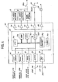
- Fig. 4 is an illustration of the detail of control unit 26. Wheel speed signals from sensos 5, 6, 7 are shaped into rectangular pulses by waveshaping circuits 30, 31, 32 and stop signal from switch 14 is fed to a buffer 33.
- Microcomputer 35 which is powered by circuit 34 in response to ignition switch 41, includes a microprocessor (CPU) 35a that receives these signals through an input/output port 35d to perform operations according to programmed instructions stored in read-only memory 35b. Temporary data are stored in RAM 35c during the process of input data which will be described in detal later.
- CPU microprocessor
- Brake control signals from microcomputer 35 are fed through drivers 36, 37, 38 to solenoid-operated actuators 17, 18, 19, respectively, which are connected in circuit with the relay contacts 24a of cut-off relay 24 which is energized by a driver 39.
- Driver 40 energizes warning light 25 under control of microcomputer 35.
- a timer 35e provides a timing pulse at regular intervals to an interrupt control unit 35f which in response to the timing pulse issues an interrupt command to microprocessor 35a.
- the microprocessor interrupts its main routine execution to execute a timer interrupt subroutine in which it selects an appropriate brake pressure gradient pattern and operates the actuators 17-19.
- microcomputer 35 When ignition switch 41 is turned on, microcomputer 35 initiates executing instructions stored in ROM 35b.
- Program shown in Fig. 5 starts with a block 101 where various temporary data such as flags are initialized.
- Control is passed to a subroutine 102 in which antiskid control go-ahead decision and start timing decision are made.
- subroutine 102 comprises three successive steps 1021 to 1023 for making decisions by proceeding with a block 1021 in which the microcomputer checks if the antiskid system is functioning properly.
- vehicle speed Vsb is compared with a reference speed (5 km/h, for example) to detect if the vehicle is higher than the reference, and in block 1023 the ON-state of stop switch 14 is detected.
- control is passed to a block 1024 to set go-ahead flag Fact and if any one of these decisions is negative control is passed to blocks 1025 and 1028 in succession to reset go-ahead flag Fact and control start flag F sta ' respectively.
- Block 1026 is then executed to detect if any one of sensed wheel speed values Vw is lower than a reference speed Vss which represents the upper limit for effecting antiskid control.
- Control is passed to block 1027 to set control start flag F sta if the speed value Vw becomes lower than reference speed Vss.
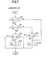
- the microcomputer then advances to a subroutine 103 to determine the degree of road surface friction.
- Fig. 7 illustrates the steps necessary to obtain such information using data representing reference wheel speed and wheel acceleration stored in ROM 35b.
- the microprocessor now proceeds to a subroutine 105, Fig. 5, to derive from vehicle speed Vsb a number of threshold values with which wheel speed and wheel acceleration values are compared to determine down pressure timing.
- Subroutine 105 is followed by a system check subroutine 106 in which the microprocessor checks system functions for abnormal conditions.
- the subroutine 106 comprises blocks 1061 to 1066.
- wheel speed sensors 5-7 are checked for abnormality such as disconnection and short-circuit condition.
- the source voltage of power circuit is checked in block 1062 for under- or over-voltage condition.
- Actuator solenoids are checked in block 1063 for disconnection and short-circuit and the down pressure operation is checked in block 1064 for abnormal prolongation. If all these functions are normal, control is passed to block 1065 to reset an abnormal flag F abn ' and if any abnormality is detected, abnormal flag F abn is set up in block 1066.
- a control signal is applied to indicator driver 40 which latches it and drives the warning light 25 to alert the vehicle occupant.
- a fail-safe subroutine 109 is executed by energizing the cut-off relay 24 to cut off the circuits to the actuators 17-19.
- the system is allowed to operate in a manual mode in which the brake pressure is applied in response to the depression of brake pedal in the usual manner. It is preferable that an arrangement be made to cut off the input circuits to actuator drivers 36-38 to ensure against the abnormality of cut-off relay 24.
- Fig. 10 is an illustration of a timer interrupt subroutine which is executed at regular intervals during program execution of the main routine.
- the interrupt routine starts with block 201 in which wheel speed Vw is determined for each of the wheels based on data derived in a wheel speed interrupt routine shown in Fig. 11 by which the main routine is also interrupted in response to the occurrrence of each wheel speed pulse. More specifically, three wheel speed interrupt programs are provided having different priorities to count simultaneously occurring wheel speed pulses at.different timing and store the count values in addressible locations of the RAM.
- the counted wheel speed pulses are read from the RAM to detect the difference between the wheel speed count of the previous execution and that derived in the current execution to derive a wheel speed digital value.
- Wheel acceleration Aw is derived in block 202 by taking a difference between wheel speed values successively derived from each wheel.
- digital filtering techniques may be employed to smooth out insignificant fluctuations.
- Control is then advanced to block 206 to check if a down-pressure mode is selected and if so, a down-pressure time counter Cdpt is incremented by one in block 207, and if not this counter is reset in block 208.
- the microprocessor checks if down-pressure time counter C d p t exceeds a preset limit, typically 3 seconds, and if so, the actuators 17-19 are deenergized in block 204 and if not, control is passed to block 210 to detect if the selected mode is an up-pressure mode and if so, an up-pressure time counter C u p t is incremented by one in block 211, and if not, this counter is reset in block 212. If the counter C u p t indicates a 3-second period (block 213), actuators are deenergized, and if not, they remain energized (block 214).
- a preset limit typically 3 seconds
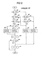
- the subroutine 205 of Fig. 10 starts with block 501 in which wheel acceleration Aw is compared with a lower threshold G 1 ,
- both wheel acceleration Aw and wheel speed Vw are higher than thresholds Gland Vsh respectively.
- Control is thus passed through blocks 501 and 502 to block 503 to increase brake pressure according to the amount of depression on the brake pedal as shown at a in Fig. 14.
- a count value C which determines the length of recyclic periods for down- and up-pressure modes, is reset to zero in block 511.
- count value C is incremented by one in block 508, and checked against a second threshold K 2 in block 509 which represents the termination of the subsequent up-pressure mode and at the same time the initiation of the next down-pressure mode, as will be understood as description proceeds. If C>K2, control exits from block 509 to the next subroutine 206 bypassing block 511.
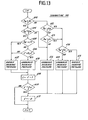
- Fig. 13 is a modification of the Fig. 12 subroutine in which gradual/rapid switching solenoids are employed in addition to up/down switching solenoids.
- Blocks 614 and 615 are added to cause control to pass to block 614 if Aw>G 1 and Vw>Vsh or Aw>G 2 and Vw ⁇ Vsh to check if Aw>G H and if so, block 615 is executed to rapidly increase the pressure and if Aw ⁇ G H block 603 is executed to gradually increase the pressure.
- Other differences reside in blocks 606 and 609 where the count value C is compared with thresholds K 3 and K 4 (where K 4 >K 3 ).
- control is initially passed through blocks 601 and 604 to block 612 to effect gradual down-pressure operation and goes to block 611 to reset counter C.
- control passes through block 601, 604, 605 and 606 to block 607 to rapidly decrease the brake pressure and goes through blocks 608 and 609 to increment counter C. Control is further passed through blocks 608 and 609, incrementing the count value C.
- gradual down-pressure mode is continued until count value C reaches threshold K 3 at time t 3 ' (block 606), whereupon control is switched to block 610 to effect gradual down-pressure mode until count value C becomes equal to threshold K 4 , resetting the counter C in block 611.
- control is passed through blocks 601, 602 and 613 to block 612 to switch the down-pressure operation to a gradual mode, terminating the alternating rapid and gradual down-pressure operations.
- This gradual down-pressure mode is continued until conditions Aw>G 2 and Vw ⁇ Vsh occur at time t 4 ' whereupon control is passed to block 614.
- conditions Aw ⁇ G H and Vw ⁇ Vsh prevail and the microprocessor proceeds to block 603 increase the brake pressure gradually.
- control is switched to block 615 to switch the up-pressure operation to rapid mode.
- wheel speed Vw becomes lower than Vsl and slip-friction flag F 1 is set up and control is passed from block 605 to block 607 to continue the rapid down-pressure mode until time t 10 '.
- block 612 is executed to provide gradual down-pressure mode.
- control is passed through blocks 601, 602, 613 and 614 to block 603 to switch the brake pressure gradient to a gradually increasing mode.
- control is passed through blocks 601, 604 to 612 to effect gradual down-pressure mode.
- control is switched from block 604 to block 605 and thence to block 607 to change the down-pressure operation to rapid mode until time t 14 '.
- control passes through blocks 601, 602, 613 and 612 to gradually decrease the brake pressure.
Landscapes
- Engineering & Computer Science (AREA)
- Transportation (AREA)
- Mechanical Engineering (AREA)
- Microelectronics & Electronic Packaging (AREA)
- Physics & Mathematics (AREA)
- Fluid Mechanics (AREA)
- Regulating Braking Force (AREA)
Applications Claiming Priority (2)
| Application Number | Priority Date | Filing Date | Title |
|---|---|---|---|
| JP145257/83 | 1983-08-09 | ||
| JP58145257A JPS6035646A (ja) | 1983-08-09 | 1983-08-09 | アンチスキツド制御装置 |
Publications (3)
| Publication Number | Publication Date |
|---|---|
| EP0133812A2 true EP0133812A2 (de) | 1985-03-06 |
| EP0133812A3 EP0133812A3 (en) | 1986-07-30 |
| EP0133812B1 EP0133812B1 (de) | 1988-12-07 |
Family
ID=15380947
Family Applications (1)
| Application Number | Title | Priority Date | Filing Date |
|---|---|---|---|
| EP84305374A Expired EP0133812B1 (de) | 1983-08-09 | 1984-08-07 | Gleitschutzsteuerung mit Oberflächenreibungskompensation |
Country Status (4)
| Country | Link |
|---|---|
| US (1) | US4666218A (de) |
| EP (1) | EP0133812B1 (de) |
| JP (1) | JPS6035646A (de) |
| DE (1) | DE3475506D1 (de) |
Cited By (2)
| Publication number | Priority date | Publication date | Assignee | Title |
|---|---|---|---|---|
| US4929035A (en) * | 1988-02-08 | 1990-05-29 | Akebono Brake Industry Co. Ltd. | Anti-lock control system for motor vehicles |
| EP0387783A3 (en) * | 1989-03-13 | 1994-12-21 | Sumitomo Electric Industries | Brake control device in an antilock brake system |
Families Citing this family (25)
| Publication number | Priority date | Publication date | Assignee | Title |
|---|---|---|---|---|
| JPH064410B2 (ja) * | 1984-06-07 | 1994-01-19 | 日産自動車株式会社 | アンチスキツド制御装置 |
| JPS60261769A (ja) * | 1984-06-07 | 1985-12-25 | Nissan Motor Co Ltd | アンチスキツド制御装置 |
| US4837727A (en) * | 1985-03-04 | 1989-06-06 | Nippon Soken, Inc. | Road surface detecting device for vehicle |
| JPH0678059B2 (ja) * | 1985-11-20 | 1994-10-05 | トキコ株式会社 | アンチスキツド制御装置 |
| JPS62146759A (ja) * | 1985-12-23 | 1987-06-30 | Nissan Motor Co Ltd | アンチスキツド制御装置 |
| JPS62152914A (ja) * | 1985-12-26 | 1987-07-07 | Nippon Soken Inc | 走行路面状態検出装置 |
| JPH0688532B2 (ja) * | 1985-12-27 | 1994-11-09 | 曙ブレーキ工業株式会社 | アンチスキツド制御方法 |
| JPS62218873A (ja) * | 1986-03-20 | 1987-09-26 | Fujitsu Ltd | 車輪速度判定処理方式 |
| DE3610186A1 (de) * | 1986-03-26 | 1987-10-01 | Bosch Gmbh Robert | Antiblockierregelsystem |
| US4807941A (en) * | 1986-06-19 | 1989-02-28 | Nippondenso Co., Ltd. | Anti-skid control system |
| JP2646572B2 (ja) * | 1987-09-04 | 1997-08-27 | 日産自動車株式会社 | アンチスキッド制御装置の擬似車速発生装置 |
| JP2593179B2 (ja) * | 1988-04-25 | 1997-03-26 | 日産自動車株式会社 | アンチスキッド制御装置 |
| EP0363570B1 (de) * | 1988-10-13 | 1996-02-21 | Japan Electronics Industry, Ltd. | Strassenoberflächen-Reibungsaufnehmer und Strassenoberflächen-Reibungskoeffizienten-Aufnehmer und Fahrzeug-Blockierschutz-Bremsanlage |
| JP2688948B2 (ja) * | 1988-10-26 | 1997-12-10 | 株式会社曙ブレーキ中央技術研究所 | 車両のアンチロック制御方法 |
| EP0379094B1 (de) * | 1989-01-14 | 1996-06-19 | Sumitomo Electric Industries, Ltd. | Antiblockier-Steuerungsgerät |
| US4916619A (en) * | 1989-04-13 | 1990-04-10 | General Motors Corporation | Adaptive wheel slip threshold |
| US5257192A (en) * | 1989-07-14 | 1993-10-26 | Nippondenso Co., Ltd. | Brake pressure control system for motor vehicles |
| US5185702A (en) * | 1989-09-08 | 1993-02-09 | Akebono Research And Development Centre Ltd. | Vehicle anti-lock control apparatus and method |
| US5043896A (en) * | 1990-06-11 | 1991-08-27 | Ford Motor Company | Vehicle braking system controller/road friction and hill slope tracking system |
| US5132906A (en) * | 1990-06-11 | 1992-07-21 | Ford Motor Company | Road surface friction and hill slope estimator |
| DE19849773A1 (de) * | 1997-10-29 | 1999-06-17 | Aisin Seiki | Antiblockiersteuerungssystem |
| JP4110634B2 (ja) * | 1998-09-30 | 2008-07-02 | アイシン精機株式会社 | アンチスキッド制御装置 |
| US6202020B1 (en) * | 1999-08-20 | 2001-03-13 | Meritor Heavy Vehicle Systems, Llc | Method and system for determining condition of road |
| JP4543484B2 (ja) * | 2000-03-07 | 2010-09-15 | 株式会社アドヴィックス | ブレーキ液圧制御装置 |
| JP3651372B2 (ja) * | 2000-08-04 | 2005-05-25 | トヨタ自動車株式会社 | 車輌用制動制御装置 |
Family Cites Families (10)
| Publication number | Priority date | Publication date | Assignee | Title |
|---|---|---|---|---|
| US3578819A (en) * | 1968-09-23 | 1971-05-18 | Kelsey Hayes Co | Skid control system |
| US3698772A (en) * | 1970-03-18 | 1972-10-17 | Borg Warner | Brake control system for pulsing vehicle brakes at variable pulse rates |
| US3674320A (en) * | 1970-07-15 | 1972-07-04 | Bendix Corp | Adaptive braking control system |
| US3717384A (en) * | 1971-03-15 | 1973-02-20 | Gen Motors Corp | Anti-lock brake control system |
| JPS5314708B2 (de) * | 1972-08-31 | 1978-05-19 | ||
| US4143926A (en) * | 1977-01-27 | 1979-03-13 | Kelsey-Hayes Co. | Skid control system |
| JPS56154355A (en) * | 1980-04-25 | 1981-11-28 | Nissan Motor Co Ltd | Anti-skid controller |
| US4395761A (en) * | 1980-05-15 | 1983-07-26 | Honda Giken Kogyo Kabushiki Kaisha | Antiskid brake controlling method and apparatus for vehicles |
| US4347569A (en) * | 1980-08-12 | 1982-08-31 | General Signal Corporation | Wheel slip system |
| DE3039512A1 (de) * | 1980-10-20 | 1982-05-06 | Knorr-Bremse GmbH, 8000 München | Blockiergeschuetzter bremskraftrgelkreis |
-
1983
- 1983-08-09 JP JP58145257A patent/JPS6035646A/ja active Granted
-
1984
- 1984-08-07 DE DE8484305374T patent/DE3475506D1/de not_active Expired
- 1984-08-07 EP EP84305374A patent/EP0133812B1/de not_active Expired
- 1984-08-08 US US06/638,717 patent/US4666218A/en not_active Expired - Lifetime
Cited By (2)
| Publication number | Priority date | Publication date | Assignee | Title |
|---|---|---|---|---|
| US4929035A (en) * | 1988-02-08 | 1990-05-29 | Akebono Brake Industry Co. Ltd. | Anti-lock control system for motor vehicles |
| EP0387783A3 (en) * | 1989-03-13 | 1994-12-21 | Sumitomo Electric Industries | Brake control device in an antilock brake system |
Also Published As
| Publication number | Publication date |
|---|---|
| JPH0553671B2 (de) | 1993-08-10 |
| EP0133812B1 (de) | 1988-12-07 |
| DE3475506D1 (en) | 1989-01-12 |
| JPS6035646A (ja) | 1985-02-23 |
| US4666218A (en) | 1987-05-19 |
| EP0133812A3 (en) | 1986-07-30 |
Similar Documents
| Publication | Publication Date | Title |
|---|---|---|
| US4666218A (en) | Antiskid control with surface friction compensation | |
| US4665490A (en) | Antiskid control with surface friction compensation by prolonged down-pressure operation | |
| US4672547A (en) | Antiskid control with surface roughness compensation | |
| US4670852A (en) | Wheel speed and acceleration detection immune to disturbance | |
| EP0133381B1 (de) | Gleitschutzsteuerung mit Unterschiedskompensation der Radgeschwindigkeit | |
| US4651281A (en) | Antiskid control with wheel-speed difference compensation | |
| US4669046A (en) | Method and system for deriving wheel rotation speed data for automotive anti-skid control | |
| US4674049A (en) | Automotive anti-skid brake control system with sampling input time data of wheel speed sensor signals | |
| EP0123279B1 (de) | Gleitschutzbremssteuersystem für Kraftfahrzeuge | |
| US4660146A (en) | Anti-lock brake control system including a procedure of sampling of input time data of wheel speed sensor signals and method therefor | |
| US4680714A (en) | Anti-skid brake control system with reduced duration of wheel acceleration and deceleration calculation | |
| EP0125613B1 (de) | Verfahren und System zur Ableitung von Radbeschleunigung und Radverzögerung in Kraftfahrzeug-Gleitschutzbremssteuersystemen | |
| US4780818A (en) | Anti-skid brake control system with control of sampling timing of input timing values of wheel speed sensor signal pulses | |
| EP0282031B1 (de) | Fahrzeug-Bremssystem für angetriebene Räder mit Mitteln zur Verzögerung des Anfangs der Bremsdruckänderung | |
| US4663715A (en) | Automotive anti-skid control system with control of sampling of input time data of wheel speed sensor signals and method therefor | |
| EP0318928A2 (de) | Blockierschutz-Steuervorrichtung | |
| US4663716A (en) | Anti-skid control system for automotive brake system with sample control for sampling input timing of sensor signal pulses with required process identification and method for sampling | |
| EP0123287A2 (de) | Verfahren und System zur Bemusterung der die Zeit betreffenden Eingangsdaten für Radgeschwindigkeitsaufnehmer in einem Kraftfahrzeug-Gleitschutz-Bremssteuersystem | |
| US4980831A (en) | Antilock control device | |
| EP0175201B1 (de) | Radschlupfregelsystem für ein Fahrzeug | |
| US4665491A (en) | Anti-skid brake control system with sample control of sensor signal input time data, and method therefor | |
| US5615934A (en) | Method and system for detecting aquaplaning of a vehicle in an anti-lock brake system | |
| EP0198691B1 (de) | Auf die Strassenoberflächen-Beschaffenheit reagierendes Antischleuder-Steuersystem | |
| US5644490A (en) | Method and system for estimating vehicle speed reference value | |
| JP2000501353A (ja) | Absの制御状態を改善する方法 |
Legal Events
| Date | Code | Title | Description |
|---|---|---|---|
| PUAI | Public reference made under article 153(3) epc to a published international application that has entered the european phase |
Free format text: ORIGINAL CODE: 0009012 |
|
| AK | Designated contracting states |
Designated state(s): DE FR GB |
|
| PUAL | Search report despatched |
Free format text: ORIGINAL CODE: 0009013 |
|
| AK | Designated contracting states |
Kind code of ref document: A3 Designated state(s): DE FR GB |
|
| 17P | Request for examination filed |
Effective date: 19861219 |
|
| 17Q | First examination report despatched |
Effective date: 19870720 |
|
| GRAA | (expected) grant |
Free format text: ORIGINAL CODE: 0009210 |
|
| AK | Designated contracting states |
Kind code of ref document: B1 Designated state(s): DE FR GB |
|
| REF | Corresponds to: |
Ref document number: 3475506 Country of ref document: DE Date of ref document: 19890112 |
|
| ET | Fr: translation filed | ||
| PLBI | Opposition filed |
Free format text: ORIGINAL CODE: 0009260 |
|
| PLBI | Opposition filed |
Free format text: ORIGINAL CODE: 0009260 |
|
| 26 | Opposition filed |
Opponent name: ALFRED TEVES GMBH Effective date: 19890821 |
|
| 26 | Opposition filed |
Opponent name: ROBERT BOSCH GMBH Effective date: 19890830 Opponent name: ALFRED TEVES GMBH Effective date: 19890821 |
|
| PGFP | Annual fee paid to national office [announced via postgrant information from national office to epo] |
Ref country code: GB Payment date: 19900727 Year of fee payment: 7 |
|
| PGFP | Annual fee paid to national office [announced via postgrant information from national office to epo] |
Ref country code: FR Payment date: 19900807 Year of fee payment: 7 |
|
| PGFP | Annual fee paid to national office [announced via postgrant information from national office to epo] |
Ref country code: DE Payment date: 19900927 Year of fee payment: 7 |
|
| RDAG | Patent revoked |
Free format text: ORIGINAL CODE: 0009271 |
|
| STAA | Information on the status of an ep patent application or granted ep patent |
Free format text: STATUS: PATENT REVOKED |
|
| 27W | Patent revoked |
Effective date: 19901130 |
|
| GBPR | Gb: patent revoked under art. 102 of the ep convention designating the uk as contracting state |