EP0133859A1 - Procédé et dispositif pour fabriquer des paquets composés de lames de tôle avec décalage de l'angle au centre pour machines électriques, en particulier des paquets de rotor-on stator - Google Patents
Procédé et dispositif pour fabriquer des paquets composés de lames de tôle avec décalage de l'angle au centre pour machines électriques, en particulier des paquets de rotor-on stator Download PDFInfo
- Publication number
- EP0133859A1 EP0133859A1 EP83810363A EP83810363A EP0133859A1 EP 0133859 A1 EP0133859 A1 EP 0133859A1 EP 83810363 A EP83810363 A EP 83810363A EP 83810363 A EP83810363 A EP 83810363A EP 0133859 A1 EP0133859 A1 EP 0133859A1
- Authority
- EP
- European Patent Office
- Prior art keywords
- depressions
- lamination
- lamella
- elevations
- rotor
- Prior art date
- Legal status (The legal status is an assumption and is not a legal conclusion. Google has not performed a legal analysis and makes no representation as to the accuracy of the status listed.)
- Granted
Links
- 238000000034 method Methods 0.000 title claims abstract description 14
- 238000004519 manufacturing process Methods 0.000 title claims abstract description 7
- 238000003475 lamination Methods 0.000 claims abstract description 11
- 241000446313 Lamella Species 0.000 claims description 25
- 238000005520 cutting process Methods 0.000 claims description 11
- 238000000926 separation method Methods 0.000 claims description 4
- 230000005540 biological transmission Effects 0.000 claims description 3
- 239000002184 metal Substances 0.000 claims description 3
- 238000004080 punching Methods 0.000 abstract description 8
- 238000004049 embossing Methods 0.000 abstract description 3
- 238000007373 indentation Methods 0.000 description 6
- 230000000712 assembly Effects 0.000 description 1
- 238000000429 assembly Methods 0.000 description 1
- 238000010924 continuous production Methods 0.000 description 1
- 230000007423 decrease Effects 0.000 description 1
- 238000010586 diagram Methods 0.000 description 1
- 238000006073 displacement reaction Methods 0.000 description 1
- 238000004806 packaging method and process Methods 0.000 description 1
- 230000000737 periodic effect Effects 0.000 description 1
- 238000003825 pressing Methods 0.000 description 1
- 238000005096 rolling process Methods 0.000 description 1
- 230000001360 synchronised effect Effects 0.000 description 1
- 238000003466 welding Methods 0.000 description 1
Images

Classifications
-
- H—ELECTRICITY
- H02—GENERATION; CONVERSION OR DISTRIBUTION OF ELECTRIC POWER
- H02K—DYNAMO-ELECTRIC MACHINES
- H02K1/00—Details of the magnetic circuit
- H02K1/06—Details of the magnetic circuit characterised by the shape, form or construction
- H02K1/22—Rotating parts of the magnetic circuit
- H02K1/26—Rotor cores with slots for windings
-
- B—PERFORMING OPERATIONS; TRANSPORTING
- B21—MECHANICAL METAL-WORKING WITHOUT ESSENTIALLY REMOVING MATERIAL; PUNCHING METAL
- B21D—WORKING OR PROCESSING OF SHEET METAL OR METAL TUBES, RODS OR PROFILES WITHOUT ESSENTIALLY REMOVING MATERIAL; PUNCHING METAL
- B21D28/00—Shaping by press-cutting; Perforating
- B21D28/02—Punching blanks or articles with or without obtaining scrap; Notching
- B21D28/22—Notching the peripheries of circular blanks, e.g. laminations for dynamo-electric machines
-
- H—ELECTRICITY
- H02—GENERATION; CONVERSION OR DISTRIBUTION OF ELECTRIC POWER
- H02K—DYNAMO-ELECTRIC MACHINES
- H02K1/00—Details of the magnetic circuit
- H02K1/06—Details of the magnetic circuit characterised by the shape, form or construction
- H02K1/12—Stationary parts of the magnetic circuit
- H02K1/16—Stator cores with slots for windings
-
- H—ELECTRICITY
- H02—GENERATION; CONVERSION OR DISTRIBUTION OF ELECTRIC POWER
- H02K—DYNAMO-ELECTRIC MACHINES
- H02K15/00—Processes or apparatus specially adapted for manufacturing, assembling, maintaining or repairing of dynamo-electric machines
- H02K15/02—Processes or apparatus specially adapted for manufacturing, assembling, maintaining or repairing of dynamo-electric machines of stator or rotor bodies
- H02K15/021—Magnetic cores
-
- H—ELECTRICITY
- H02—GENERATION; CONVERSION OR DISTRIBUTION OF ELECTRIC POWER
- H02K—DYNAMO-ELECTRIC MACHINES
- H02K2201/00—Specific aspects not provided for in the other groups of this subclass relating to the magnetic circuits
- H02K2201/06—Magnetic cores, or permanent magnets characterised by their skew
Definitions
- the invention relates to a method for producing packages of electrical machines consisting of stacked sheet metal lamellae with circular central openings and elongated grooves, in particular rotor or stator packages, which are twisted so that they form helical through openings in packages, in which method identical strips are punched out of a band and are indented on one side with indentations and on the other side with indentations that correspond to and oppose the indentations, which protrusions during assembly of each package into the indentations, the depth of which is at least fifty percent the lamella thickness has reached, engage with pretension, whereby in the case of one lamella per package, which serves as a separating lamella, a cylindrical hole is drilled instead of the depression, into which the b engages adjacent slat, and a device for performing the method, consisting of a follow-up tool with a male and female mold and with several workstations.
- the packages with helically twisted grooves on the outer or inner contour are common.
- the packages consist of a large number of individual lamellae, which are punched out of a punched strip, whereby they are provided with circular central openings and elongated grooves.
- stamping with a stamp while counteracting the force of the counterpart
- the slats are provided with indentations on one side and elevations that match and oppose the indentations on the other side.
- the lamellae formed in this way are stacked on top of each other with a center angle offset.
- a separation lamella is used, in which a cylindrical hole is punched instead of the recess, into which the elevation of the adjacent lamella engages.
- the invention specified in claim 1 is based on the object of proposing or creating a method and a device for producing packages of electrical machines consisting of stacked sheet metal lamellae with circular central openings and elongated grooves, in which the known method and the known device in be further improved in the sense that the packages are manufactured precisely in a single continuous production.
- the device according to the invention for carrying out the method is characterized in that the outer surface of the die carrier is in the cutout position tion with a worm gear toothing in which a driven worm engages rhythmically intermittently, or is provided with a gear toothing in which a toothed rack driving the gear transmission engages rhythmically intermittently.
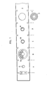
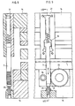
- rotor lamellae 2 with circular central openings 12 and elongated grooves 13 are punched out of a punching tape 1 (see FIG. 1) and layered on top of one another in order to form rotor packs of electrical machines.
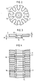
- the identical rotor lamellae 2 are simultaneously provided with recesses 10 on one side in the same follow-up tool and on the other side with elevations 11 which match and oppose the recesses 10 in the form of deposits (FIG. 3). This is done in flow embossing by means of stamps (not shown) while counter-stamps are subjected to counterforce.
- the deposits 11 are pre-stressed into the depressions 10, the depth of which has reached at least fifty percent of the lamella thickness.
- one lamella, which serves as a separating lamella 17 is provided with a cylindrical hole 18 instead of a depression 10 and a shoulder 11 (see working position C in FIG. 1). The step 11 of the adjacent lamella then engages in the hole 18.
- the separation lamella 17 is periodically perforated (hole 18) after a predetermined number of lamellae, the hole diameter corresponding to the protruding part of the shoulder 11 of the adjacent lamella 2.
- the package length thus corresponds to the number of individual slats connected to each other.
- the depressions 10 and the steps 11 are flow-stamped concentrically around the previously punched-out central openings 12.
- the depressions 10 and deposits 11 can be formed at any radial distance from the central openings 12. They can have the shape of a circular ring or the shape of circular arcs.
- the height H of each step 11 is smaller than the depth t of each depression 10, so that the lamellae 2 which are connected to one another after the steps 11 have been pressed into the wells 10 lie flat on one another (FIG. 4).
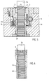
- a rotatably mounted cutting station 15 is partially shown.
- This cutting station 15 is located in the lower part 16 of the following tool.
- a cutting ring 6 is seated on a rotatable, tube-like die carrier 3.
- the die carrier 3 is provided on its outer surface with a worm gear toothing 4, in which a worm 5 engages and drives the cutting ring rotation movement rhythmically intermittently in the press cycle.
- the drive of the screw 5 can be carried out for packages with grooves 13 twisted at a uniform pitch (see FIG. 11) by the press, not shown, directly via its ram movement.
- the worm or a gear transmission not shown, which engages in a gear toothing formed on the outer surface of the die carrier with a press-side synchronized self-drive, e.g. B. are driven rhythmically intermittently by means of a stepping motor.
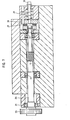
- a part 21 is moved back and forth in the upper tool part 14 by the ram movement (FIGS. 8 and 9). With this movable part 21 one end of a rack 7 is connected, which end is accommodated in the slot 32 of the part 21 under spring loading.
- the other end of the rack 7 has a toothing 22 which is in engagement in the lower tool part 16 with the toothing of a drive wheel 23.
- a pressure roller 24 for guiding the rack 7 is provided on the side of the rack 7 opposite the drive wheel 23.
- the stroke size of the rack 7 is adjustable by means of a screw 25.
- the drive wheel 23 is provided with a one-way clutch, not shown, and lies on one end of the worm shaft 26 which carries the worm 5 (FIG. 7). On the other end, the worm shaft 26 is supported against a friction brake 27. The pressure on the friction brake 27 can be adjusted by means of a screw 30 via a spring 29 and a disk 28. The worm shaft 26 is supported in ball bearings 31.
- the drive wheel 23 and thus the worm shaft 26 with the worm 5 are rotated intermittently by a desired angle. This rotary movement is via the worm gear teeth . 4 transferred to the die carrier 3. As a result, the rotor blade last cut and connected to the package is displaced by the desired center angle before the subsequent blade, which is being cut, is connected to this previously cut blade.
- the drive wheel 23 rotates and thus the worm shaft 26 during the return stroke of the toothed rack 7, but not during its decline, because the drive wheel is then uncoupled by the one-way clutch.
- the finished lamellae 2 are connected to one another in the cutting station 15 by the pressure exerted by the stamp 34, which stamp is in its lowermost position.
- the die carrier 3 is provided with the gear teeth instead of the worm gear teeth.
- a machine-driven cam worm gear or a machine-synchronized self-propulsion is suitable.
- the production of packages with lamella groups offset by 180 ° from one another only requires periodic forward and backward rotation of the die ring carrier 3. In this case, a machine-controlled, double-acting rack and pinion drive is sufficient.
- three brake elements 19 acting radially on the cut-out disks 2 are also installed (FIG. 10). These produce the resistance required for pressing the above shoulder 11 onto the lamella 2 being cut into the recess 10 of the lamella 2 cut out beforehand.
- the brake elements are loaded by disc springs 33.
- a package discharge channel 20 is also flanged to the die carrier 3, which also brakes elements can be installed.
- the finished lamellae with offset of the central angle are connected to finished packages in a single follow-on tool.
- the axial connecting force between the slats ensures that the packets can be handled safely during further processing.
- the pitch of the helical groove twist i.e. the offset of the center angle from lamella to lamella, is adjustable or controllable.
Landscapes
- Engineering & Computer Science (AREA)
- Power Engineering (AREA)
- Manufacturing & Machinery (AREA)
- Mechanical Engineering (AREA)
- Manufacture Of Motors, Generators (AREA)
Priority Applications (3)
| Application Number | Priority Date | Filing Date | Title |
|---|---|---|---|
| DE8383810363T DE3369444D1 (en) | 1983-08-15 | 1983-08-15 | Method and device for manufacturing electric machine packets made of sheet plates with displaced centre angle, especially for rotor or stator cores |
| EP83810363A EP0133859B1 (fr) | 1983-08-15 | 1983-08-15 | Procédé et dispositif pour fabriquer des paquets composés de lames de tôle avec décalage de l'angle au centre pour machines électriques, en particulier des paquets de rotor-on stator |
| ES535080A ES535080A0 (es) | 1983-08-15 | 1984-08-10 | Procedimiento para fafricar paquetes de maquinas electricas,particularmente paquetes de rotores o estatores. |
Applications Claiming Priority (1)
| Application Number | Priority Date | Filing Date | Title |
|---|---|---|---|
| EP83810363A EP0133859B1 (fr) | 1983-08-15 | 1983-08-15 | Procédé et dispositif pour fabriquer des paquets composés de lames de tôle avec décalage de l'angle au centre pour machines électriques, en particulier des paquets de rotor-on stator |
Publications (2)
| Publication Number | Publication Date |
|---|---|
| EP0133859A1 true EP0133859A1 (fr) | 1985-03-13 |
| EP0133859B1 EP0133859B1 (fr) | 1987-01-21 |
Family
ID=8191560
Family Applications (1)
| Application Number | Title | Priority Date | Filing Date |
|---|---|---|---|
| EP83810363A Expired EP0133859B1 (fr) | 1983-08-15 | 1983-08-15 | Procédé et dispositif pour fabriquer des paquets composés de lames de tôle avec décalage de l'angle au centre pour machines électriques, en particulier des paquets de rotor-on stator |
Country Status (3)
| Country | Link |
|---|---|
| EP (1) | EP0133859B1 (fr) |
| DE (1) | DE3369444D1 (fr) |
| ES (1) | ES535080A0 (fr) |
Cited By (7)
| Publication number | Priority date | Publication date | Assignee | Title |
|---|---|---|---|---|
| EP0306631A3 (en) * | 1987-09-08 | 1989-11-15 | Nippondenso Co., Ltd. | Metal plate laminated body |
| DE4308318A1 (de) * | 1993-03-16 | 1994-10-13 | Waasner Elektrotechnische Fabr | Verfahren zur Herstellung von lose zu Stangen aufgereihten Blechstapeln aus gestanzten Blechen und Vorrichtung zur Durchführung des Verfahrens |
| RU2172051C1 (ru) * | 2000-12-15 | 2001-08-10 | ООО "КД-Электро" | Способ изготовления ротора электрической машины |
| US7249546B1 (en) | 1991-05-13 | 2007-07-31 | Franklin Electric Co., Ltd. | Die-shaping apparatus and process and product formed thereby |
| EP1859876A1 (fr) * | 2006-05-24 | 2007-11-28 | Ernesto Malvestiti S.p.A. | Dispositif de centrage pour des matrices de poinçonnage |
| EP2056428A3 (fr) * | 2007-10-29 | 2013-04-24 | Kabushiki Kaisha Toyota Jidoshokki | Procédé de fixation d'une culasse dans un carter et compresseur comprenant un stator pareil |
| DE102012010638B4 (de) * | 2011-06-06 | 2025-02-20 | Secop Gmbh | Rotor mit einem Ölabfluss |
Citations (1)
| Publication number | Priority date | Publication date | Assignee | Title |
|---|---|---|---|---|
| DE2838685A1 (de) * | 1978-09-05 | 1980-03-06 | Mitsui Mfg Co | Vorrichtung zur herstellung von geschichteten kernen |
Family Cites Families (3)
| Publication number | Priority date | Publication date | Assignee | Title |
|---|---|---|---|---|
| US3110831A (en) * | 1961-07-19 | 1963-11-12 | Gen Motors Corp | Dynamoelectric machine core assembly |
| EP0042046B1 (fr) * | 1980-06-16 | 1984-07-18 | International Business Machines Corporation | Méthode et appareils de fabrication d'une structure feuilletée de machine dynamoélectrique |
| DE3163159D1 (en) * | 1980-06-16 | 1984-05-24 | Ibm | Method of, and apparatus for, constructing a laminated rotor |
-
1983
- 1983-08-15 DE DE8383810363T patent/DE3369444D1/de not_active Expired
- 1983-08-15 EP EP83810363A patent/EP0133859B1/fr not_active Expired
-
1984
- 1984-08-10 ES ES535080A patent/ES535080A0/es active Granted
Patent Citations (1)
| Publication number | Priority date | Publication date | Assignee | Title |
|---|---|---|---|---|
| DE2838685A1 (de) * | 1978-09-05 | 1980-03-06 | Mitsui Mfg Co | Vorrichtung zur herstellung von geschichteten kernen |
Non-Patent Citations (1)
| Title |
|---|
| Patent Abstracts of Japan Band 5, Nr. 40, 17. März 1981 & JP-A-55-162840 * |
Cited By (8)
| Publication number | Priority date | Publication date | Assignee | Title |
|---|---|---|---|---|
| EP0306631A3 (en) * | 1987-09-08 | 1989-11-15 | Nippondenso Co., Ltd. | Metal plate laminated body |
| US7249546B1 (en) | 1991-05-13 | 2007-07-31 | Franklin Electric Co., Ltd. | Die-shaping apparatus and process and product formed thereby |
| DE4308318A1 (de) * | 1993-03-16 | 1994-10-13 | Waasner Elektrotechnische Fabr | Verfahren zur Herstellung von lose zu Stangen aufgereihten Blechstapeln aus gestanzten Blechen und Vorrichtung zur Durchführung des Verfahrens |
| RU2172051C1 (ru) * | 2000-12-15 | 2001-08-10 | ООО "КД-Электро" | Способ изготовления ротора электрической машины |
| EP1859876A1 (fr) * | 2006-05-24 | 2007-11-28 | Ernesto Malvestiti S.p.A. | Dispositif de centrage pour des matrices de poinçonnage |
| US8166636B2 (en) | 2006-05-24 | 2012-05-01 | Ernesto Malvestiti S.p.A. | Apparatus with a centering device for positioning and cutting a laminate |
| EP2056428A3 (fr) * | 2007-10-29 | 2013-04-24 | Kabushiki Kaisha Toyota Jidoshokki | Procédé de fixation d'une culasse dans un carter et compresseur comprenant un stator pareil |
| DE102012010638B4 (de) * | 2011-06-06 | 2025-02-20 | Secop Gmbh | Rotor mit einem Ölabfluss |
Also Published As
| Publication number | Publication date |
|---|---|
| ES8602311A1 (es) | 1985-11-01 |
| EP0133859B1 (fr) | 1987-01-21 |
| DE3369444D1 (en) | 1987-02-26 |
| ES535080A0 (es) | 1985-11-01 |
Similar Documents
| Publication | Publication Date | Title |
|---|---|---|
| DE69714849T2 (de) | Verfahren und vorrichtung zur herstellung eines blechpaketes | |
| EP1269608B1 (fr) | Appareil de production de paquets formes d'elements en tole | |
| EP3021466B1 (fr) | Procede de fabrication de paquets de lamelles et installation d'execution du procede | |
| DE19931932B4 (de) | Anfas-Verfahren sowie Presse | |
| DE2245576A1 (de) | Verpackung mit elektrischen einzelteilen | |
| DE19634723A1 (de) | Verfahren zum Herstellen und Schichten von Bauteilen | |
| EP0133858A1 (fr) | Procédé et dispositif pour fabriquer des paquets composés de lames de tôle pour des noyaux magnétiques de machines électriques | |
| EP2012951A1 (fr) | Procédé de fabrication d'une roue dentée | |
| EP0133859B1 (fr) | Procédé et dispositif pour fabriquer des paquets composés de lames de tôle avec décalage de l'angle au centre pour machines électriques, en particulier des paquets de rotor-on stator | |
| DE3883325T2 (de) | Lammellierter Körper von Metallblechen. | |
| DE3434463C2 (fr) | ||
| EP2481495B1 (fr) | Procédé de fabrication de produits finis constitués de piles de lamelles | |
| EP2982456A1 (fr) | Dispositif et procédé de fabrication d'un élément de couplage à dents ou ayant des parties dentées adaptées aux systèmes de synchronisation | |
| DE102017203701A1 (de) | Vorrichtung und Verfahren zur Herstellung eines Gewindeformteils | |
| EP3741032B1 (fr) | Procédé d'assemblage d'éléments de tôle à des paquets de tôle | |
| DE2719075A1 (de) | Verfahren und schneidwerkzeug zur herstellung von elektromotorenblechen sowie elektromotorenblech | |
| DE102007043582B3 (de) | Rotor für eine Rundlauf-Tablettenpresse | |
| DE2838685A1 (de) | Vorrichtung zur herstellung von geschichteten kernen | |
| DE112023006688T5 (de) | Folgeverbundwerkzeugvorrichtung und verfahren zum herstellen einer eisenkernschicht | |
| WO2015070834A1 (fr) | Installation de découpe en rotation | |
| DE3638571C2 (fr) | ||
| EP1410857A2 (fr) | Procédé de fabrication de paquets de tôles de forme annulaire pour des machines électriques multipolaires | |
| EP0082537A1 (fr) | Procédé de fabrication de paquets de tôles et dispositif pour sa mise en oeuvre | |
| DE3203123A1 (de) | Verfahren zum herstellen eines lamellenpaketes fuer anker elektrischer maschinen | |
| DE19845388C2 (de) | Vorrichtung und Verfahren zur Herstellung von Plattenwärmetauschern aus vorgefertigten Wärmetauscherplatten |
Legal Events
| Date | Code | Title | Description |
|---|---|---|---|
| PUAI | Public reference made under article 153(3) epc to a published international application that has entered the european phase |
Free format text: ORIGINAL CODE: 0009012 |
|
| 17P | Request for examination filed |
Effective date: 19840711 |
|
| AK | Designated contracting states |
Designated state(s): DE FR GB IT |
|
| 17Q | First examination report despatched |
Effective date: 19860121 |
|
| GRAA | (expected) grant |
Free format text: ORIGINAL CODE: 0009210 |
|
| AK | Designated contracting states |
Kind code of ref document: B1 Designated state(s): DE FR GB IT |
|
| REF | Corresponds to: |
Ref document number: 3369444 Country of ref document: DE Date of ref document: 19870226 |
|
| ET | Fr: translation filed | ||
| ITF | It: translation for a ep patent filed | ||
| PLBI | Opposition filed |
Free format text: ORIGINAL CODE: 0009260 |
|
| PLBI | Opposition filed |
Free format text: ORIGINAL CODE: 0009260 |
|
| 26 | Opposition filed |
Opponent name: KIENLE & SPIESS STANZ- UND DRUCKGIEBWERK GMBH Effective date: 19871020 |
|
| 26 | Opposition filed |
Opponent name: SIEMENS AKTIENGESELLSCHAFT, BERLIN UND MUENCHEN Effective date: 19871021 |
|
| PLAB | Opposition data, opponent's data or that of the opponent's representative modified |
Free format text: ORIGINAL CODE: 0009299OPPO |
|
| PLAB | Opposition data, opponent's data or that of the opponent's representative modified |
Free format text: ORIGINAL CODE: 0009299OPPO |
|
| R26 | Opposition filed (corrected) |
Opponent name: KIENLE & SPIESS STANZ- UND DRUCKGIEBWERK GMBH * 87 Effective date: 19871020 |
|
| R26 | Opposition filed (corrected) |
Opponent name: KIENLE & SPIESS STANZ- UND DRUCKGIEBWERK GMBH * 87 Effective date: 19871020 |
|
| PGFP | Annual fee paid to national office [announced via postgrant information from national office to epo] |
Ref country code: GB Payment date: 19900711 Year of fee payment: 8 Ref country code: FR Payment date: 19900711 Year of fee payment: 8 |
|
| PGFP | Annual fee paid to national office [announced via postgrant information from national office to epo] |
Ref country code: DE Payment date: 19900730 Year of fee payment: 8 |
|
| ITTA | It: last paid annual fee | ||
| RDAG | Patent revoked |
Free format text: ORIGINAL CODE: 0009271 |
|
| STAA | Information on the status of an ep patent application or granted ep patent |
Free format text: STATUS: PATENT REVOKED |
|
| 27W | Patent revoked |
Effective date: 19910123 |
|
| GBPR | Gb: patent revoked under art. 102 of the ep convention designating the uk as contracting state |