EP0133886B1 - Regelvorrichtung für die Erntebergungsvorrichtung einer Erntemaschine - Google Patents
Regelvorrichtung für die Erntebergungsvorrichtung einer Erntemaschine Download PDFInfo
- Publication number
- EP0133886B1 EP0133886B1 EP84106910A EP84106910A EP0133886B1 EP 0133886 B1 EP0133886 B1 EP 0133886B1 EP 84106910 A EP84106910 A EP 84106910A EP 84106910 A EP84106910 A EP 84106910A EP 0133886 B1 EP0133886 B1 EP 0133886B1
- Authority
- EP
- European Patent Office
- Prior art keywords
- switch
- control device
- collector
- switching
- crop
- Prior art date
- Legal status (The legal status is an assumption and is not a legal conclusion. Google has not performed a legal analysis and makes no representation as to the accuracy of the status listed.)
- Expired
Links
- 238000003306 harvesting Methods 0.000 claims description 44
- 230000033001 locomotion Effects 0.000 claims description 14
- 230000009347 mechanical transmission Effects 0.000 claims description 9
- 230000005540 biological transmission Effects 0.000 claims description 8
- 230000001960 triggered effect Effects 0.000 description 4
- 238000010586 diagram Methods 0.000 description 3
- 210000005069 ears Anatomy 0.000 description 2
- 241001124569 Lycaenidae Species 0.000 description 1
- 238000010276 construction Methods 0.000 description 1
- 230000001276 controlling effect Effects 0.000 description 1
- 238000004519 manufacturing process Methods 0.000 description 1
- 239000000463 material Substances 0.000 description 1
- 238000000034 method Methods 0.000 description 1
- 230000001105 regulatory effect Effects 0.000 description 1
- 239000002689 soil Substances 0.000 description 1
Images


Classifications
-
- A—HUMAN NECESSITIES
- A01—AGRICULTURE; FORESTRY; ANIMAL HUSBANDRY; HUNTING; TRAPPING; FISHING
- A01D—HARVESTING; MOWING
- A01D41/00—Combines, i.e. harvesters or mowers combined with threshing devices
- A01D41/12—Details of combines
- A01D41/14—Mowing tables
- A01D41/141—Automatic header control
-
- A—HUMAN NECESSITIES
- A01—AGRICULTURE; FORESTRY; ANIMAL HUSBANDRY; HUNTING; TRAPPING; FISHING
- A01D—HARVESTING; MOWING
- A01D41/00—Combines, i.e. harvesters or mowers combined with threshing devices
- A01D41/10—Field threshers with windrow pick-up apparatus
-
- Y—GENERAL TAGGING OF NEW TECHNOLOGICAL DEVELOPMENTS; GENERAL TAGGING OF CROSS-SECTIONAL TECHNOLOGIES SPANNING OVER SEVERAL SECTIONS OF THE IPC; TECHNICAL SUBJECTS COVERED BY FORMER USPC CROSS-REFERENCE ART COLLECTIONS [XRACs] AND DIGESTS
- Y10—TECHNICAL SUBJECTS COVERED BY FORMER USPC
- Y10S—TECHNICAL SUBJECTS COVERED BY FORMER USPC CROSS-REFERENCE ART COLLECTIONS [XRACs] AND DIGESTS
- Y10S56/00—Harvesters
- Y10S56/15—Condition responsive
Definitions
- the invention relates to a control device for the harvesting device of a harvesting machine with an adjusting device, which has an electrically controllable lifting part and an electrically controllable lowering part, for pivoting the harvesting device, which is equipped with a pick-up device and a pull-in part, on which the pick-up device, which is supported on the ground by means of wheels is connected with its trailing end via a transverse axis to the front end of the pull-in part in an articulated and pivotable manner, the side parts of the pick-up device being designed to be torsionally rotatable and for this purpose at least one electrical rotary switch which can be actuated via ground contact members of the pull-in part is provided as an adjusting device between them and the pull-in part is, via the switching impulses to the electro-hydraulically actuable control device for changing the position of the feed part relative to the pick-up device g and the rotary switch has an input contact that can be connected to a power supply device and a plurality of output contacts that are
- a device for combine harvesters for controlling the height of a cutting device is already known (EP-A 0 048127), which is mounted on numerous links arranged side by side.
- the individual links for receiving the flexibly designed cutting device are supported on a sensor shaft which is received in holders of the harvesting device.
- a shift lever is fixedly connected to a rotary switch.
- the continuous shaft for receiving the individual height-pivotable handlebars is adjusted when a single handlebar changes its height, regardless of the position of the other handlebars, so that the height of the harvesting device is adjusted when a single handlebar triggers a switching pulse .
- a combine harvester with a harvesting device is known (US-A 4171 606), which is equipped with a feed part and a band collecting device pivotally connected thereto; the rear end of the collecting device is connected in an articulated manner to the intake part, while it is supported on the floor by means of running wheels.
- the belt collecting device consists of side parts running parallel to one another, which are connected to one another via the axes of the rollers of a conveyor belt, mutual adjustment of the side parts being possible.
- Sensors are assigned to the belt collecting device on both sides, which act between the belt collecting device and the pull-in part and contribute to influencing an adjusting device in such a way that the position of the belt collecting device is kept constant without an excessive load on the conveyor belt occurring. Since an electrical sensor is assigned to each side part, an electrical switching device for the lowering circuit and also for the lifting circuit must also be assigned to each sensor, so that a very complex switching device results, which leads to an increase in the cost of the entire control device.
- the invention is based on the object of designing and arranging the automatic control device for the harvesting device with a band collecting device connected thereto in such a way that only one sensor or switching element can be used to influence the electro-hydraulic control device.
- This object is achieved by the features listed in the characterizing part of claim 1. Due to the advantageous arrangement of a single rotary switch on one side of the harvesting device in connection with the transmission device, one obtains an advantageous regulation of the harvesting device with little construction effort, so that optimal use of the associated belt is always guaranteed even when using a belt collecting device.
- the electro-hydraulic control device ensures that there is a corresponding change in position of the belt collecting device and that it always assumes an approximately horizontal position with respect to the standing area of the combine.
- the transmission device detects the relative movement between the tape collecting device and the feed part in a simple manner and always brings about a correction of the position of the tape collecting device. Due to the advantageous transmission device, sensors and the transmission linkage associated therewith can be saved.
- a further electrical switch makes it possible to adjust the working position of the belt collecting device to the different crop properties or position of the harvested material and thus to fix the belt collecting device to a certain distance from the ground.
- the rotary switch has a rotatable switching part provided on the transmission device and that the mechanical transmission device for adjusting the switching part has a spring which adjusts the switching part to a first position, in the first position the transmission device in its working position for pivoting the depending on the pivoting movement of the pick-up device device is located.
- the mechanical transmission device which acts between the intake part and the tape collecting device, the relative movement between these two structural units can be transmitted in a simple manner, and thus the rotatably mounted switch can be adjusted when it has been pivoted into its final working position via the spring.
- the final working position of the switching part is only reached when a parallel pivoting, ie a uniform adjustment of all frame parts or side parts, has been brought about. If only one side part is adjusted relative to the other frame parts, the switching part and the mechanical transmission device connected to it cannot assume their final working position and thus no corresponding switching impulse for changing the height of the tape collecting device can be triggered.
- the mechanical transmission device has a shaft spanning the width of the pick-up device, at the ends of which a lever arm is connected, which is in operative connection with the frame of the retractable part and which by pivoting the pick-up device up into a first position and adjusted to a second position by the spring.
- the shaft extends between the upper and lower runs of the collecting device. It is also advantageous that the rotary switch is arranged on the shaft and can be pivoted coaxially with it.
- the mechanical transmission device has two linkages which are connected to the frame of the pull-in part in an articulated manner, each link having its respective upper end connected to the corresponding lever arm of the shaft, and that the linkages on one end on frame parts of the pull-in part, on the other end are connected to the corresponding lever arm via the slot connection designed as a slot guide.
- an intermediate space with a currentless contact element is provided between the first and second output contact elements, so that when the rotary switch is used, the pickup device is floatingly supported and the pickup device has two mutually parallel, single axes or has jointly pivotable side parts which are connected to one another at least via a telescopic connecting device running parallel to the axis.
- the use of numerous output contacts, which can be connected to the input contact via the switching element, enables specific height positions for the band collecting device to be controlled.
- the use of the telescopic connecting device creates a good but elastic connection between the outer frame parts of the tape collecting device.
- 10 denotes a self-propelled harvesting machine, for example a combine harvester, which is supported on rear and front wheels 12 and is equipped with a driver's cab 14, under which the harvesting device 16 is connected.
- a self-propelled harvesting machine for example a combine harvester, which is supported on rear and front wheels 12 and is equipped with a driver's cab 14, under which the harvesting device 16 is connected.
- the harvesting device 16 is equipped with a belt collecting device 18 which is firmly connected to an inclined conveyor housing 20 which is connected below the driver's cab 14 by means of a combine harvester 10.
- the vertical adjustment of the harvesting device 16 he follows via hydraulic cylinders 24, which are connected to a hydraulic motor via hydraulic lines and can be actuated via electrical switching elements 26 and 28 and an electro-hydraulic control device 30.
- the tape collecting device 18 is illustrated in detail in FIGS. 2 and 3 and equipped with an automatic position control device. Between the inclined conveyor housing 20 and the belt collecting device 18 there is a feed part 32 with a feed screw 64 which is rigidly connected to the lower end of the inclined conveyor housing 20 and receives the frame parts 34 of the floating belt collecting device 18.
- the frame parts 34 of the tape collecting device 18 can pivot freely about a transverse axis 36.
- the distance from the front end of the tape collecting device 18 to the floor is controlled by two running wheels 38 which are connected to a frame 40 of the tape collecting device 18 and are arranged in front of the frame 40 or the tape collecting device 18 with reference to FIG. 1.
- the belt collecting device 18 has a conveyor belt 42 with numerous fingers 44 (see FIG. 1), the conveyor belt 42 being guided around rear rollers 46, front rollers 48 and a middle roller 50.
- the conveyor belt 42 is driven by a hydraulic motor 52, which for this purpose is connected to the corresponding roller 46, which runs coaxially to the axis 36 of the belt collecting device 18.
- the upper run of the conveyor belt 42 serves for receiving and for further transport of the picked crop, the corresponding part of the run 54 being on an increasing level with respect to the conveying direction of the crop, while the part 56 of the run is on a downwardly inclined plane .
- the roller 50 supports the upper run 54 and lies in the kink of the two parts of the upper run.
- Cover parts 58 which are provided above the conveyor belt 42, serve to hold the crop on the conveyor belt and to support the conveyance to the feed part 32.
- the pull-in part 32 has a frame 60 to which two opposite side parts 62 (see FIGS. 1 and 2) are connected.
- the side parts 62 serve to receive the auger 64, which pulls the harvested crop from the conveyor belt 42 and directs it to the inclined conveyor housing 20 and thus into the interior of the combine harvester.
- Skids 66 and 67 are also connected to the frame 60 on both sides and extend from the frame 60 to the front. They serve to pivot the harvesting device 16, to support the frame part 34 and ensure a minimum height of the intake part 32 to the ground.
- the position of the harvesting device 16, in particular the front end of the conveyor belt 42 with the front roller 48, and a parallel alignment of the front end to the ground are particularly important.
- the rear end of the conveyor belt or the associated frame parts 34 are rigidly connected to the feed part.
- an adjustment of the front roller 48 or a transverse inclination of the front roller 48 with respect to the rear roller 46 is possible.
- the frame part 34 is designed to be flexible.
- the side parts 68 and 70 of the frame part 34 are connected to one another via a connecting device 72.
- the connecting device 72 consists of two telescopic parts 74 and 76 which can be rotated about a horizontal axis of the smile. This enables a torsional movement, so that the side parts 68 and 70 can be pivoted against one another.
- the automatic control device is shown in more detail in FIG. 1, which includes a shaft 80 of a sensor device 82 which extends between the upper and the lower run of the conveyor belt 42 and is received in the side parts 68 and 70.
- the rearwardly extending lever arms 84 and 86 are connected on the left and right to the shaft 80 outside the side parts 68 and 70.
- Each lever arm 84 and 86 each has a bearing pin 88 to which a linkage 92 and 94 is connected.
- a spring 90 is connected at one end to the lever arm 86 outside of the side part 70 and biases the sensor device 82 in a clockwise direction with reference to FIG. 3.
- Input pulses on the sensor device 82 indicate the pivoting or rotating movement of the frame parts 34.
- the shaft 80 is operatively connected to a switching device 100, which is provided at the right end of the shaft 80.
- the switching device 100 is secured against rotation with respect to the frame part 34 and for this purpose has a housing part 102 which is connected to a holder 104 connected to the side part 70.
- An electrical switching panel 106 is arranged on the inside of the housing 102, past which a pivotable switching element 108 passes, which is firmly connected to the shaft 80.
- the switching panel 106 has switching contacts 110 arranged on a circular arc, to which a single input switching element 112 is assigned. The inputs and outputs of the switching contacts 110 and the input switching part 112 are connected via a brush device 114 which is arranged on the switching element 108.
- the connection of the housing 102 to the holder 104 takes place via a bolt which is received in a slot guide 109, so that a pivoting movement is possible.
- This adjustment option serves to compensate for manufacturing inaccuracies.
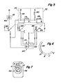
- the position of the frame meners 34 with respect to the feed section 32 is controlled from the driver's cab 14 via a switch 154 which is designed as a three-pole four-position switch. The switching positions are indicated according to FIG. 7 by a scale 156.
- the switch 154 is connected to the electro-hydraulic control device 30 via electrical lines 158.
- a second cable connection is used to connect the electro-hydraulic control device 30 to the switching device 100.
- FIG. 5 illustrates a circuit diagram for the automatic height and position control device of the harvesting device 16 with reference to the frame part 34 opposite the feed part 32.
- a power wave 28 is shown in the circuit diagram, which may include a battery 164, for example, which is part of the electro-hydraulic control device 30, which includes a circuit 170 for raising and a circuit 172 for lowering the harvesting device.
- Circuits 170 and 172 for raising and lowering harvesting device 16 include switching relays 174 (raising) and 176 (lowering), as well as a coil 178 (raising) and a coil 180 (lowering), respectively.
- the switch 154 has an off position A and three operating positions B, C and D, which correspond to a specific position of the harvesting device.
- the switch 154 shown schematically in FIG. 1 is pulled apart and consists of three switch contacts 182, 184 and 186 arranged coaxially to one another (each switch contact corresponds to one pole of the switch).
- the relative position of each switching segment corresponds to the four switching positions A, B, C and D, as indicated in FIG.
- the electrical function of the switching device 100 results from the circuit according to FIG. 5.
- the operator has to set the switch 154 for a corresponding working height. Thereafter, the harvesting device 16 is manually brought into the appropriate height position via the individual control elements, the height of the front end of the frame part 34 being controlled by the running wheels 38, so that the frame parts 34 assume the desired position with respect to the feed part 32 and then one automatic height control or height control takes place. After the appropriate adjustment of the harvesting device 16 has been made, the operator can release the switch 154 and the automatic control system takes over the altitude control.
- the switching element 108 is connected directly to the shaft 80, which responds to the corresponding height of the frame part 34 and thereby adjusts the brush device 114 with reference to the individual contacts of the switching panels 106 and corresponding control pulses “lifting” or “Lowering” triggers and thus brings the harvesting device 16 into the desired working position.
- the dimensions and the spacing of the switching contacts 110 and the dimensions of the brush device 114 are selected such that the brush device 114 can be arranged above the contacts, while at the same time ensuring that the switching arrangement functions properly.
- the number or the spacing of the individual contacts can be changed accordingly or selected so as to vary the area of application for height adjustment of the harvesting device 16 accordingly.
- five output contacts and a selector switch are provided, which enable three working positions for the harvesting device 16.
- the individual contacts can be individually connected to the individual circuits 170 and 172 in such a way that they correspond to the corresponding switch positions of the switch 154 in the driver's cab 14.
- the circuit described corresponds to end contacts, wherein the circuits 170 and 172 are only responsible for raising or lowering.
- the three intermediate outputs can be connected to either circuit 170 (raise) or circuit 172 (lower). Furthermore, they can be connected to a zero line in which no switching process is triggered. If the individual contacts or the brush device are not connected to the circuits 170 and 172, in this case the harvesting device or the frame part 34 can move up and down freely without a corresponding switching impulse “raising” or “lowering”. for the harvesting device 16 (inclined conveyor housing with feed part 32).
- Effective picking up or harvesting of the crop depends on the correct pulling of the conveyor belt 42.
- the frame part 34 pivots downward about its axis 36.
- the angle of inclination of the conveyor belt or of the upper run is increased, while this is reduced by lowering the harvesting device.
- good harvesting is achieved when the rear part 56 of the upper run 54 assumes an approximately horizontal position or parallel to the base of the combine harvester is aligned.
- position C of switch 154 corresponds to the normal working position of the harvesting device or conveyor belt 42. With positions B and D, a slight inclination or a strong inclination of conveyor belt 42 is set.
- the automatic regulating or control device also works effectively when the combine harvester is working on uneven terrain, since the frame parts 34 can be twisted or twisted. 3, the left side part 68 can be lowered more than the right side part 70 on uneven terrain.
- the spring 90 forces the lever arms 84 and 86 upwards, so that the bearing pin 88 of the right lever arm 86 from the upper end of the Slot guide 96 of the left linkage 94 is moved away.
- the relative downward movement of the left side part 68 causes the left lever arm 84 to move vertically, so that the left bearing pin 88 moves away from the upper end of the slot guide 96 of the linkage 92.
- the foregoing shows that the compact and simple design of the sensor device 82 in conjunction with a mechanical adjusting device ensures that the conveyor belt 42 can always be aligned parallel to the floor surface during work and can follow the contours of the floor surface when the floor surface is uneven.
- the play connection between the shaft 80 and the frame parts of the harvesting device 16 triggers a switching pulse for upward adjustment when one or the other side of the band collecting device 18 is moved upward, while a downward movement of both sides of the band collecting device 18 triggers a switching pulse for downward movement.
- the linkages 92, 94 connected to the shaft 80 thus only cause an adjustment of the shaft and thus of the switching device 100 for upward adjustment, while the spring 90 only adjusts the shaft 80 for the lowering pulse.
Landscapes
- Life Sciences & Earth Sciences (AREA)
- Environmental Sciences (AREA)
- Harvester Elements (AREA)
- Guiding Agricultural Machines (AREA)
Applications Claiming Priority (2)
| Application Number | Priority Date | Filing Date | Title |
|---|---|---|---|
| US06/509,882 US4567719A (en) | 1983-07-01 | 1983-07-01 | Attitude control for a harvester pickup |
| US509882 | 1983-07-01 |
Publications (2)
| Publication Number | Publication Date |
|---|---|
| EP0133886A1 EP0133886A1 (de) | 1985-03-13 |
| EP0133886B1 true EP0133886B1 (de) | 1988-01-07 |
Family
ID=24028476
Family Applications (1)
| Application Number | Title | Priority Date | Filing Date |
|---|---|---|---|
| EP84106910A Expired EP0133886B1 (de) | 1983-07-01 | 1984-06-16 | Regelvorrichtung für die Erntebergungsvorrichtung einer Erntemaschine |
Country Status (5)
| Country | Link |
|---|---|
| US (1) | US4567719A (da) |
| EP (1) | EP0133886B1 (da) |
| CA (1) | CA1227345A (da) |
| DE (1) | DE3468305D1 (da) |
| DK (1) | DK320984A (da) |
Cited By (2)
| Publication number | Priority date | Publication date | Assignee | Title |
|---|---|---|---|---|
| US8945152B2 (en) | 2005-05-20 | 2015-02-03 | Neotract, Inc. | Multi-actuating trigger anchor delivery system |
| EP3697193B1 (de) * | 2017-10-17 | 2025-02-26 | Grimme Landmaschinenfabrik GmbH & Co. KG | Siebbandeinheit für eine erntemaschine sowie zugehörige klappeneinheit |
Families Citing this family (21)
| Publication number | Priority date | Publication date | Assignee | Title |
|---|---|---|---|---|
| US4967544A (en) * | 1989-01-05 | 1990-11-06 | Deere & Company | Automatic speed control system for a harvesting assembly |
| US5123234A (en) * | 1990-10-02 | 1992-06-23 | Kubota Corporation | Working vehicle having a mower unit vertically movable relative to a vehicle body |
| DE4328351A1 (de) * | 1993-08-24 | 1995-03-02 | Kloeckner Humboldt Deutz Ag | Aufnahmevorrichtung für Erntegut |
| US6050075A (en) * | 1997-09-16 | 2000-04-18 | New Holland North America, Inc. | Lateral float apparatus for windrow pickup attachment |
| CA2257049A1 (en) * | 1997-12-31 | 1999-06-30 | Richard Gramm | Combine header height control |
| GB0101557D0 (en) * | 2001-01-22 | 2001-03-07 | Ford New Holland Nv | Drive mechanism for a front attachment of an agricultural harvesting machine and corresponding front attachment |
| US6918237B2 (en) * | 2003-07-21 | 2005-07-19 | Cnh America Llc | Feeder position sensor |
| US6883299B1 (en) | 2003-08-05 | 2005-04-26 | Richard Gramm | Height sensor arrangement for agricultural applications |
| CA2631888A1 (en) * | 2004-12-10 | 2006-06-15 | Innotech Pty Ltd | Guide and agricultural machine incorporating same |
| DE102005001412B4 (de) * | 2005-01-12 | 2007-01-11 | Maschinenfabrik Kemper Gmbh & Co. Kg | Wagen zur Abstützung eines Erntevorsatzes bei einer Straßenfahrt |
| US7726111B2 (en) * | 2005-06-30 | 2010-06-01 | Deere & Company | Suspension system for a belt pickup header in an agricultural harvester |
| DE102008049130A1 (de) * | 2008-09-26 | 2010-04-01 | Claas Selbstfahrende Erntemaschinen Gmbh | Landwirtschaftliche Erntemaschine |
| US8122694B2 (en) * | 2009-09-21 | 2012-02-28 | Cnh America Llc | Suspension system for a crop harvesting header |
| US8276356B2 (en) * | 2010-02-26 | 2012-10-02 | Deere & Company | Tractor mounted cotton harvester |
| US8266881B2 (en) * | 2010-03-29 | 2012-09-18 | Cnh America Llc | Flexible motor support system for a crop gathering device having a harvesting header |
| US7971420B1 (en) * | 2010-08-31 | 2011-07-05 | Deere & Company | Draper platform suspension |
| US9913426B2 (en) | 2015-09-30 | 2018-03-13 | Cnh Industrial America Llc | Control sensor assembly for an agricultural harvester |
| DE102018108879A1 (de) * | 2018-04-13 | 2019-10-17 | Grimme Landmaschinenfabrik Gmbh & Co. Kg | Siebbandeinheit für eine Erntemaschine oder für eine Ernteguttransporteinheit, zugehörige Klappeneinheit |
| US20220304233A1 (en) * | 2021-03-25 | 2022-09-29 | James E. Straeter | Stover conveyor system |
| EP4066617B1 (en) | 2021-03-31 | 2025-05-07 | CNH Industrial Belgium N.V. | A belt drive for driving the header of a combine harvester |
| US12495741B2 (en) * | 2021-10-28 | 2025-12-16 | Deere & Company | Harvesting machine belt pickup header with movable pickup belt assembly |
Family Cites Families (4)
| Publication number | Priority date | Publication date | Assignee | Title |
|---|---|---|---|---|
| US4211057A (en) * | 1978-03-20 | 1980-07-08 | Massey-Ferguson Industries Limited | Combine harvester automatic table height control |
| US4171606A (en) * | 1978-06-30 | 1979-10-23 | Deere & Company | Attitude control for a harvester pickup |
| US4304089A (en) * | 1980-02-11 | 1981-12-08 | Mescheryakov Ivan K | Pickup of a farm machine |
| US4332126A (en) * | 1980-09-11 | 1982-06-01 | Deere & Company | Automatic height control for a harvester header |
-
1983
- 1983-07-01 US US06/509,882 patent/US4567719A/en not_active Expired - Lifetime
-
1984
- 1984-05-30 CA CA000455446A patent/CA1227345A/en not_active Expired
- 1984-06-16 DE DE8484106910T patent/DE3468305D1/de not_active Expired
- 1984-06-16 EP EP84106910A patent/EP0133886B1/de not_active Expired
- 1984-06-29 DK DK320984A patent/DK320984A/da not_active Application Discontinuation
Cited By (2)
| Publication number | Priority date | Publication date | Assignee | Title |
|---|---|---|---|---|
| US8945152B2 (en) | 2005-05-20 | 2015-02-03 | Neotract, Inc. | Multi-actuating trigger anchor delivery system |
| EP3697193B1 (de) * | 2017-10-17 | 2025-02-26 | Grimme Landmaschinenfabrik GmbH & Co. KG | Siebbandeinheit für eine erntemaschine sowie zugehörige klappeneinheit |
Also Published As
| Publication number | Publication date |
|---|---|
| EP0133886A1 (de) | 1985-03-13 |
| DK320984A (da) | 1985-01-02 |
| DK320984D0 (da) | 1984-06-29 |
| CA1227345A (en) | 1987-09-29 |
| US4567719A (en) | 1986-02-04 |
| DE3468305D1 (en) | 1988-02-11 |
Similar Documents
| Publication | Publication Date | Title |
|---|---|---|
| EP0133886B1 (de) | Regelvorrichtung für die Erntebergungsvorrichtung einer Erntemaschine | |
| EP0234585B1 (de) | Mähdrescher | |
| DE602004012495T2 (de) | Erntegutaufnahmevorrichtung und Erntefahrzeug | |
| DE69107582T2 (de) | Erntemaschine, besonders Mähmaschine, die leicht von einer Arbeitstellung in eine Transportstellung versetzt werden kann. | |
| EP0168665B1 (de) | Rückwärtig an eine Erntemaschine angebaute Schwadablegeeinrichtung | |
| DE4021030C2 (de) | Mähtisch für Erntemaschinen | |
| EP0160823A1 (de) | Mähdrescher | |
| DE2924434A1 (de) | Vorrichtung zum selbsttaetigen steuern der arbeitslage der aufnehmervorrichtung von erntemaschinen, insbesondere maehdreschern | |
| DE102012108835A1 (de) | Schneidwerk | |
| EP3689118B1 (de) | Landwirtschaftliches arbeitsgerät, deichselvorrichtung und zugfahrzeug-arbeitsgerät-kombination | |
| EP2529614B1 (de) | Mähwerkskombination | |
| EP0156125B1 (de) | Trommelschwader | |
| EP1093708A1 (de) | Mähgerät | |
| DE4214466A1 (de) | Steuereinrichtung für eine pendelnd gelagerte Baugruppe an einer landwirtschaftlichen Maschine | |
| EP1796454B1 (de) | Erntegerät, insbesondere erntevorsatz für landwirtschaftliche erntemaschinen zum aufnehmen und weiterfördern von halmfrüchten | |
| EP0205854B1 (de) | Fördervorrichtung für landwirtschaftliche Ladewagen | |
| DE69705013T2 (de) | Heuwerbungsmaschine | |
| DE68914836T2 (de) | Erntemaschine. | |
| DE102019201333A1 (de) | Landwirtschaftliches Arbeitsgerät, Deichselvorrichtung und Zugfahrzeug-Arbeitsgerät-Kombination | |
| DE69512559T2 (de) | Heuwerbungsmaschine, insbesondere ein Schwader für Futter | |
| DE29714523U1 (de) | Gezogene Mähmaschine mit einer seitlich angehängten Zugstange | |
| EP1258184B1 (de) | Arbeitsaggregatekombination | |
| BE1026568B1 (de) | Selbstfahrende erntemaschine mit einer überladeeinrichtung | |
| DE102006030508B4 (de) | Anordnung zur pendelnden Aufhängung eines Erntevorsatzes an einer Erntemaschine | |
| EP4505858B1 (de) | Bandschneidwerk |
Legal Events
| Date | Code | Title | Description |
|---|---|---|---|
| PUAI | Public reference made under article 153(3) epc to a published international application that has entered the european phase |
Free format text: ORIGINAL CODE: 0009012 |
|
| AK | Designated contracting states |
Designated state(s): BE DE FR GB IT SE |
|
| EL | Fr: translation of claims filed | ||
| ITCL | It: translation for ep claims filed |
Representative=s name: LENZI & C. |
|
| 17P | Request for examination filed |
Effective date: 19850720 |
|
| 17Q | First examination report despatched |
Effective date: 19860709 |
|
| ITF | It: translation for a ep patent filed | ||
| GRAA | (expected) grant |
Free format text: ORIGINAL CODE: 0009210 |
|
| AK | Designated contracting states |
Kind code of ref document: B1 Designated state(s): BE DE FR GB IT SE |
|
| GBT | Gb: translation of ep patent filed (gb section 77(6)(a)/1977) | ||
| REF | Corresponds to: |
Ref document number: 3468305 Country of ref document: DE Date of ref document: 19880211 |
|
| ET | Fr: translation filed | ||
| PLBE | No opposition filed within time limit |
Free format text: ORIGINAL CODE: 0009261 |
|
| STAA | Information on the status of an ep patent application or granted ep patent |
Free format text: STATUS: NO OPPOSITION FILED WITHIN TIME LIMIT |
|
| 26N | No opposition filed | ||
| PGFP | Annual fee paid to national office [announced via postgrant information from national office to epo] |
Ref country code: DE Payment date: 19930817 Year of fee payment: 10 |
|
| PGFP | Annual fee paid to national office [announced via postgrant information from national office to epo] |
Ref country code: GB Payment date: 19940519 Year of fee payment: 11 |
|
| PGFP | Annual fee paid to national office [announced via postgrant information from national office to epo] |
Ref country code: SE Payment date: 19940617 Year of fee payment: 11 Ref country code: FR Payment date: 19940617 Year of fee payment: 11 |
|
| PGFP | Annual fee paid to national office [announced via postgrant information from national office to epo] |
Ref country code: BE Payment date: 19940622 Year of fee payment: 11 |
|
| ITTA | It: last paid annual fee | ||
| EAL | Se: european patent in force in sweden |
Ref document number: 84106910.7 |
|
| PG25 | Lapsed in a contracting state [announced via postgrant information from national office to epo] |
Ref country code: DE Effective date: 19950301 |
|
| PG25 | Lapsed in a contracting state [announced via postgrant information from national office to epo] |
Ref country code: GB Effective date: 19950616 |
|
| PG25 | Lapsed in a contracting state [announced via postgrant information from national office to epo] |
Ref country code: SE Effective date: 19950617 |
|
| PG25 | Lapsed in a contracting state [announced via postgrant information from national office to epo] |
Ref country code: BE Effective date: 19950630 |
|
| BERE | Be: lapsed |
Owner name: DEERE & CY Effective date: 19950630 |
|
| GBPC | Gb: european patent ceased through non-payment of renewal fee |
Effective date: 19950616 |
|
| PG25 | Lapsed in a contracting state [announced via postgrant information from national office to epo] |
Ref country code: FR Effective date: 19960229 |
|
| EUG | Se: european patent has lapsed |
Ref document number: 84106910.7 |
|
| REG | Reference to a national code |
Ref country code: FR Ref legal event code: ST |