EP0133989A2 - Elément de construction, en particulier élément de mur en forme de panneau - Google Patents
Elément de construction, en particulier élément de mur en forme de panneau Download PDFInfo
- Publication number
- EP0133989A2 EP0133989A2 EP84109107A EP84109107A EP0133989A2 EP 0133989 A2 EP0133989 A2 EP 0133989A2 EP 84109107 A EP84109107 A EP 84109107A EP 84109107 A EP84109107 A EP 84109107A EP 0133989 A2 EP0133989 A2 EP 0133989A2
- Authority
- EP
- European Patent Office
- Prior art keywords
- radiation
- component according
- window
- irradiation
- solar
- Prior art date
- Legal status (The legal status is an assumption and is not a legal conclusion. Google has not performed a legal analysis and makes no representation as to the accuracy of the status listed.)
- Withdrawn
Links
Images

Classifications
-
- E—FIXED CONSTRUCTIONS
- E04—BUILDING
- E04C—STRUCTURAL ELEMENTS; BUILDING MATERIALS
- E04C2/00—Building elements of relatively thin form for the construction of parts of buildings, e.g. sheet materials, slabs, or panels
- E04C2/44—Building elements of relatively thin form for the construction of parts of buildings, e.g. sheet materials, slabs, or panels characterised by the purpose
- E04C2/52—Building elements of relatively thin form for the construction of parts of buildings, e.g. sheet materials, slabs, or panels characterised by the purpose with special adaptations for auxiliary purposes, e.g. serving for locating conduits
- E04C2/521—Building elements of relatively thin form for the construction of parts of buildings, e.g. sheet materials, slabs, or panels characterised by the purpose with special adaptations for auxiliary purposes, e.g. serving for locating conduits serving for locating conduits; for ventilating, heating or cooling
- E04C2/525—Building elements of relatively thin form for the construction of parts of buildings, e.g. sheet materials, slabs, or panels characterised by the purpose with special adaptations for auxiliary purposes, e.g. serving for locating conduits serving for locating conduits; for ventilating, heating or cooling for heating or cooling
-
- E—FIXED CONSTRUCTIONS
- E04—BUILDING
- E04B—GENERAL BUILDING CONSTRUCTIONS; WALLS, e.g. PARTITIONS; ROOFS; FLOORS; CEILINGS; INSULATION OR OTHER PROTECTION OF BUILDINGS
- E04B1/00—Constructions in general; Structures which are not restricted either to walls, e.g. partitions, or floors or ceilings or roofs
- E04B1/62—Insulation or other protection; Elements or use of specified material therefor
- E04B1/74—Heat, sound or noise insulation, absorption, or reflection; Other building methods affording favourable thermal or acoustical conditions, e.g. accumulating of heat within walls
- E04B1/76—Heat, sound or noise insulation, absorption, or reflection; Other building methods affording favourable thermal or acoustical conditions, e.g. accumulating of heat within walls specifically with respect to heat only
- E04B1/78—Heat insulating elements
- E04B1/80—Heat insulating elements slab-shaped
-
- F—MECHANICAL ENGINEERING; LIGHTING; HEATING; WEAPONS; BLASTING
- F24—HEATING; RANGES; VENTILATING
- F24S—SOLAR HEAT COLLECTORS; SOLAR HEAT SYSTEMS
- F24S20/00—Solar heat collectors specially adapted for particular uses or environments
- F24S20/60—Solar heat collectors integrated in fixed constructions, e.g. in buildings
- F24S20/63—Solar heat collectors integrated in fixed constructions, e.g. in buildings in the form of windows
-
- F—MECHANICAL ENGINEERING; LIGHTING; HEATING; WEAPONS; BLASTING
- F24—HEATING; RANGES; VENTILATING
- F24S—SOLAR HEAT COLLECTORS; SOLAR HEAT SYSTEMS
- F24S23/00—Arrangements for concentrating solar-rays for solar heat collectors
- F24S23/30—Arrangements for concentrating solar-rays for solar heat collectors with lenses
-
- F—MECHANICAL ENGINEERING; LIGHTING; HEATING; WEAPONS; BLASTING
- F24—HEATING; RANGES; VENTILATING
- F24S—SOLAR HEAT COLLECTORS; SOLAR HEAT SYSTEMS
- F24S23/00—Arrangements for concentrating solar-rays for solar heat collectors
- F24S23/70—Arrangements for concentrating solar-rays for solar heat collectors with reflectors
-
- F—MECHANICAL ENGINEERING; LIGHTING; HEATING; WEAPONS; BLASTING
- F24—HEATING; RANGES; VENTILATING
- F24S—SOLAR HEAT COLLECTORS; SOLAR HEAT SYSTEMS
- F24S80/00—Details, accessories or component parts of solar heat collectors not provided for in groups F24S10/00-F24S70/00
- F24S80/60—Thermal insulation
-
- F—MECHANICAL ENGINEERING; LIGHTING; HEATING; WEAPONS; BLASTING
- F24—HEATING; RANGES; VENTILATING
- F24S—SOLAR HEAT COLLECTORS; SOLAR HEAT SYSTEMS
- F24S23/00—Arrangements for concentrating solar-rays for solar heat collectors
- F24S23/70—Arrangements for concentrating solar-rays for solar heat collectors with reflectors
- F24S2023/83—Other shapes
- F24S2023/834—Other shapes trough-shaped
-
- F—MECHANICAL ENGINEERING; LIGHTING; HEATING; WEAPONS; BLASTING
- F24—HEATING; RANGES; VENTILATING
- F24S—SOLAR HEAT COLLECTORS; SOLAR HEAT SYSTEMS
- F24S23/00—Arrangements for concentrating solar-rays for solar heat collectors
- F24S23/70—Arrangements for concentrating solar-rays for solar heat collectors with reflectors
- F24S2023/86—Arrangements for concentrating solar-rays for solar heat collectors with reflectors in the form of reflective coatings
-
- Y—GENERAL TAGGING OF NEW TECHNOLOGICAL DEVELOPMENTS; GENERAL TAGGING OF CROSS-SECTIONAL TECHNOLOGIES SPANNING OVER SEVERAL SECTIONS OF THE IPC; TECHNICAL SUBJECTS COVERED BY FORMER USPC CROSS-REFERENCE ART COLLECTIONS [XRACs] AND DIGESTS
- Y02—TECHNOLOGIES OR APPLICATIONS FOR MITIGATION OR ADAPTATION AGAINST CLIMATE CHANGE
- Y02B—CLIMATE CHANGE MITIGATION TECHNOLOGIES RELATED TO BUILDINGS, e.g. HOUSING, HOUSE APPLIANCES OR RELATED END-USER APPLICATIONS
- Y02B10/00—Integration of renewable energy sources in buildings
- Y02B10/20—Solar thermal
-
- Y—GENERAL TAGGING OF NEW TECHNOLOGICAL DEVELOPMENTS; GENERAL TAGGING OF CROSS-SECTIONAL TECHNOLOGIES SPANNING OVER SEVERAL SECTIONS OF THE IPC; TECHNICAL SUBJECTS COVERED BY FORMER USPC CROSS-REFERENCE ART COLLECTIONS [XRACs] AND DIGESTS
- Y02—TECHNOLOGIES OR APPLICATIONS FOR MITIGATION OR ADAPTATION AGAINST CLIMATE CHANGE
- Y02E—REDUCTION OF GREENHOUSE GAS [GHG] EMISSIONS, RELATED TO ENERGY GENERATION, TRANSMISSION OR DISTRIBUTION
- Y02E10/00—Energy generation through renewable energy sources
- Y02E10/40—Solar thermal energy, e.g. solar towers
Definitions
- the invention relates to a component, in particular a plate-shaped wall element, with an insulating layer having a predetermined thickness and a predetermined thermal insulation value.
- thermal insulation boards for example made of rigid polyurethane foam
- glass pane systems with single or multiple glazing. While the insulation panels serve the sole purpose of ensuring adequate thermal insulation and, in particular, of reducing the heat flow from areas of higher temperature to areas with lower temperatures, the purpose of glass pane systems, in addition to translucency, is also the radiation of enclosed spaces To enable solar energy and its transfer into heat, for example to take advantage of the so-called "greenhouse effect" for heating or air conditioning enclosed spaces.
- the present invention is intended to provide a component which is suitable for allowing a maximum of high-energy solar radiation to pass through, as is the case with glass pane systems, but which is more effective in comparison with glass pane systems Reduce leakage of the solar energy transferred into long-wave radiation to a minimum. It is therefore intended according to the invention to create a plate-shaped element in particular, which enables the so-called "greenhouse effect" to be used for heating or air-conditioning wall surfaces and / or closed rooms in a far more effective manner than is the case with known glass pane systems .
- This object is achieved in a component according to the preamble of claim 1 in that at least one irradiation window that is transparent for the area of the solar spectrum extends through the element.
- the task solution according to the invention therefore consists in the creation of a component which, with high thermal insulation, has a high irradiation factor for the solar radiation, but in which, in view of the irradiation window for the area of the solar spectrum, which has only limited cross-sections in relation to the element area, the retroreflection of transferred heat radiation to a minimum is reduced.
- the component according to the invention can be used, for example, as a curtain wall of an outer wall and as a covering surface for flat or pitched roofs, but also as wall-forming element, for example in industrial or sports halls, and finally also as a covering surface for solar collectors.
- the irradiation window can be a channel which extends essentially perpendicularly to the surface of the element pointing outwards and points towards the irradiation side and which has a circular cross section or can be designed as an elongated rectangular channel with a large length extension in relation to its width can.
- the surfaces of the incident window can advantageously be designed to be reflective or to be coated with a reflective material.
- a further embodiment provides that the radiation window, which can be designed as a channel extending through the element, opens out with different cross sections on both sides of the element. It has proven to be advantageous if the larger cross-section opening of the radiation window points outwards during the heating period and thus faces the solar radiation source.
- the element can thus also be designed as a turning element.
- a disc of transparent material covering the radiation window is expediently arranged on the side of the element pointing outward toward the radiation side, the pane on the inside with a known, selective IR remote Be rich reflective coating can be provided.
- Solar radiation that radiates through the radiation window passes through the aforementioned cover pane and the radiation window and is transferred to long-wave heat radiation on the other side of the element, which can face, for example, an enclosed space.
- This long-wave heat radiation is essentially absorbed by the large parts of the insulation layer, but it cannot reflect back through the channel forming the radiation window if the pane covering the channel on the radiation side, which can be made of glass or plastic, has a selectively distant IR range reflective coating is provided.
- An increase in the heat energy gain can also be achieved if at least one layer which selectively reflects in the far IR range extends through the cross section of the radiation window and can be arranged on a glass or plastic pane which runs transversely to the radiation window breaking through the insulation layer.
- a particularly important embodiment of the invention consists in that an incident solar radiation-compacting input element is arranged on the element side of the radiation window pointing outward toward the radiation side.
- This input element can be a radiation concentration chamber narrowing from the outside pointing towards the solar radiation source to an opening field, and a radiation guiding channel opening out on the side of the component facing away from the radiation side can be connected to said opening field.
- Directly onto the element surface pointing towards the irradiation side or diffusely incident solar radiation is bundled by means of such an input element and passes with high energy density through the irradiation window, which is narrow in comparison to the surface area of the component, in order to be transferred into heat radiation by means of absorption media arranged behind the component.
- the radiation-condensing input element is a lens system, the focal point of which lies in the entry field of the incident window in the latter.
- the lens system forming the input element can be a Fresnel lens, for example one that is designed as a thin-walled pane and is glued to the underside of the pane covering the irradiation window.
- a holographic lens can of course also be used, and the wall surfaces of a radiation concentration chamber narrowing onto an opening window of the radiation window can be covered with a solar radiation-absorbing layer, so that radiation that is not focused into the channel opening and that the wall surfaces fall, are absorbed and emitted again as long-wave heat radiation and are guided into the channel opening according to the principle of an integrating sphere via the IR reflective layers of a single-beam cover plate.
- the radiation-compressing input element can also be a non-focusing parabolic concentrator, the parabolic radiation guide chamber of which extends in the opening field of the radiation window extending through the element.
- the wall surfaces of such a system are expediently designed to be substantially reflective.
- This parabolic radiation guide chamber can have such a geometrical design that the angular range in which incident solar rays experience a concentration on the opening field of the radiation window is limited, for example in such a way that, while maximizing the concentration value, those in the summer months at an elevation angle between about 55 ° and 70 ° incident solar radiation does not lead to a concentration on the entrance field of the radiation window, but rather is reflected back in the opposite direction.
- the radiation-condensing input element is a hyperbolic convex mirror system with a focusing effect, in which mirror surfaces are arranged around the opening field of the incident window and a focal point and in the focal point of these mirror surfaces there is a mirror surface which is aligned with the opening field bundled energy flow of high density is reflected in the opening field of the incident window.
- the focal point of the mirror surfaces arranged around the opening field is expediently in the area of the underside jer to arrange the pane of transparent material covering the irradiation window on the irradiation side.
- the mirror surfaces extending around the opening field and the mirror surface lying in their focal point can expediently be arranged in a profile body.
- a solar radiation valve which fills its cross section extends in the radiation window and is transparent to incident solar radiation, but has a blocking effect for long-wave heat radiation.
- a particularly advantageous and simple embodiment of such a solar radiation valve consists in the use of a highly evacuated thin-walled glass body which is adapted to the cross-sectional shape of the radiation window extending through the element.
- This glass body can expediently be a radiation concentration chamber of the radiation window arranged on the radiation side.
- a converging lens ver as incident solar radiation on the radiation side inside the glass body sealing element is arranged.
- This converging lens can be a plastic lens which is produced by introducing liquid plastic into the glass body and subsequently curing the plastic compound.
- the glass body advantageously extends in the vicinity of the opening field between a radiation concentration chamber arranged on the radiation side and a radiation guide channel opening out on the element side facing away from the radiation side through the radiation window.
- the glass body forming the solar radiation valve can expediently be an evacuated hollow body, in particular a spherical or oval hollow body.
- a highly evacuated glass tube as the solar radiation valve.
- the glass body forming the solar radiation valve is rotatably received in the radiation window about an axis running approximately parallel to the outer surface of the element and over a part of its circumference in the vicinity of the opening field of the radiation window with a reflection in the solar spectral range, optionally as a result of rotation of the glass body If the coating on the radiation entry or exit side is provided, general control of the energy flow is achieved in a simple manner.
- the glass body is rotated about its axis so that the coated part fills the inlet or outlet opening of the radiation window and the solar radiation is then reflected in the direction of the radiation without entering the radiation window or a light guide channel of the radiation window to enter.
- Another possibility of controlling the heat flow when using converging lenses as radiation-compressing input elements is to disorient the lens body by means of suitable mechanical devices, that is to say to displace it in its plane or to tilt it about an axis of rotation in order to bring about a focus shift. Even with such focusing concentrators, the focused beam does not then pass through the radiation window or into a radiation guide channel of the radiation window that extends through the insulating layer.
- a tube which is transparent in the region of the solar spectrum and which absorbs or conducts absorbing fluid extends through the gap-shaped channel forming the irradiation window.
- This embodiment is therefore the formation of an element with the additional function as a solar collector. If in the insolation window or a radiation guide channel of the insolation window A fixed insulation element, for example in the form of a highly-evacuated, thin-walled glass cylinder, is arranged on the inside of the room from which the fluid-absorbing pipe, this leads to a solar high-performance collector.
- a cover plate covering the radiation window is arranged on the element side remote from the radiation side. If this cover plate is made of transparent material, there is an essentially unimpeded incidence of light through the irradiation window.
- the inside cover plate can also be a light-diffusing glass pane or a double-wall sheet made of transparent plastic.
- an absorption layer covering the irradiation window can also be arranged on the element side remote from the irradiation side, by means of which solar radiation of high energy density incident through the irradiation window is transferred into long-wave heat radiation.
- the absorption layer can advantageously be a pane with a "low-emissive layer on the inside.
- the irradiation windows with different cross-sections open out on both sides of the element and the component is designed as a reversible element, there is the advantage that by rotating the element by 180 ° in the summer months the side with the smaller ones Opening cross sections of the insolation windows to the outside, that is to say pointing to the solar radiation source, can be set and this alone can reduce the incidence of light and solar energy to the side of the element facing away from the radiation.
- Another important embodiment of the invention consists in a translucent design of the component with an insulating layer made of translucent plastic material, for example in the form of foam material.
- the insulating layer consists of a rigid polyurethane foam plate 11, the surface 12 of which is covered by a glass pane 14 on the side 13 facing the incident solar rays.
- a glass pane 14 On the hard foam plate 11 extend over their surface area arranged arranged irradiation windows with channels 15 extending approximately perpendicular to the outwardly facing plate surface 12, which are narrow in relation to the plate size and have circular cross sections.
- Funnel-like extensions 16 which are covered on the outside by a glass pane 14, adjoin the channels 15 of the radiation window.
- Fresnel lenses 18 are glued to the underside 17 of the glass pane as radiation-compressing input elements, which are circular converging lenses designed as flat panes.
- thin-walled, highly-evacuated glass bodies 20, 20 are arranged in the so-called opening field 19 of the irradiation window 19, and the rigid foam panel 11 is covered by a transparent double-walled panel 22 on the element side 21 remote from the irradiation side.
- the component illustrated in FIG. 1 is a partially transparent element, which can be designed, for example, as a curtain wall, but also as a wall or roof element.
- Solar radiation incident to the element side pointing towards the environment is focused by the Fresnel lenses 18, the focal points of which are located in or on the side of the associated channel 15 remote from the opening field 19, and the solar energy stream thus compressed enters and passes through the glass body 20 into the channel this and the light-scattering double web plate 22 assigned to the inside of the element on the side 21 behind the element, that is, for example, into a space enclosed by the element.
- these can be provided with reflective layers.
- solar radiation transferred into long-wave heat radiation is therefore not able to radiate back through the insolation window and is absorbed by the portions of the rigid foam plate 11 that are large in comparison to the cross sections of the insolation window.
- the highly evacuated glass bodies 20 in the opening field 19 of the channels 15 in the vicinity of the channel inlet or outlet opening can be coated with a layer reflecting in the solar spectral range and otherwise rotatably mounted. If the passage of solar radiation is to be prevented, for example in the summer moons, the glass bodies 20 are rotated by means of a device of no interest here and also not shown, about their axes of rotation which run approximately parallel to the element surface, in such a way that the coated glass body parts are the inlet or outlet openings of the channels Fill in 15. The solar radiation is then reflected in the direction of the radiation without entering the channel.
- a radiation window also extends through the element with a channel 26 penetrating the insulating layer of the element which is designed as a rigid foam plate 25.
- the radiation-condensing input element is designed as a non-focusing parabolic concentrator 27, the radiation guide chamber 28 of which is on the outside, i.e. on the incidence side of the solar radiation, in turn by one on the Surface 29 of the hard foam plate 25 applied glass sheet 30 is covered.
- a thin-walled, highly evacuated glass body 32 with a partial coating of its surface is in turn rotatably supported as a solar radiation valve in the vicinity of the inlet opening of the channel.
- an absorption layer 33 which transfers the high energy density through the channel into long-wave heat radiation is arranged at a distance from the latter. The retroreflected heat radiation resulting from the impact of the bundled solar radiation on the absorption media lying behind the insulation layer is absorbed by the large areas of the insulation layer.
- a non-focusing parabolic concentrator 27 as a radiation-compressing input element has the advantage that ent speaking design of the parabolic radiation guide chamber 28, the angular range that leads to a radiation concentration in the opening field 31 of the radiation guide channel 26 is to be limited. Radiation occurring outside the predetermined angular range then leads to total reflection to the outside, that is to say the radiation is immediately radiated back out of the paraboloid in the opposite direction.
- the geometry of the paraboloid should preferably be designed in such a way that, while maximizing the concentration value, the solar radiation incident in the summer months at an elevation angle of approximately 55 ° to 70 ° no longer leads to an image or concentration on the entry surface 31 of the channel 26 , but to re-emerge from paraboloid 28.
- a hyperbolic convex mirror system 35 with a focusing effect is used as the input element.
- the mirror surfaces 36, 37 which are realized in a single profile body 38, extend around the opening field 39 of the radiation guiding channel 40 of the radiation window and are oriented axially to the channel extending approximately perpendicular to the element surface through the insulating layer formed as a hard foam plate 41 Underside of the focal point located on the plate covering the insulating layer on the radiation side, in which the mirror surface 37 directed towards the opening field of the channel is arranged.
- the channel 47 of the radiation window extending through the insulation layer which is a hard foam plate 46
- the channel 47 of the radiation window extending through the insulation layer is designed in the manner of an elongated gap and, accordingly, the highly evacuated glass body 49 lying in the opening field 48 of this channel as an elongated tube.
- a tube 51 which is transparent in the region of the solar spectrum and extends to receive and conduct an absorbing fluid, extends parallel to the tubular glass body in the gap serves.
- a glass pane 52 on the underside of which the Fresnel lens is glued, in turn covers the channel.
- This configuration can be operated as a transparent solar collector system with forced passage or as a corresponding passive thermosiphon system.
- a partial covering made of a solid foam for example rigid polyurethane foam
- standing liquid columns such as water or salts melting at low temperatures, can also be accommodated here as heat energy stores. If water is used as the fluid, the transmission of the solar radiation in the visible region into the interior of a space enclosed by such an element is not impeded, while the radiation outside the visible region is completely absorbed with an energy component of approximately 50%.
- FIG. 5 illustrates the development of such an element into a solar high-performance collector, in which the line 51 carrying the absorbing fluid is received in the form of elongated tubes between two highly evacuated glass bodies 49, 49 '.
- the glass body 49 'extending on the side of the pipeline 51 carrying the fluid remote from the radiation side forms a fixed insulation element on the inside of the room.
- a light-scattering web double plate 53 is arranged on the inside of the element.
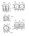
- Gap-shaped radiation windows 62 extend through the insulation layer at a distance from one another, in which highly evacuated glass tubes 63 are received as solar radiation valves.
- the insulating layer is covered with the glass tubes 63 accommodated in the irradiation windows 62 by means of a glass pane 65 extending at a distance from the insulating layer surface 64, while a pane 66 made of absorption glass is also arranged on the side remote from the irradiation side at a distance from the corresponding surface of the insulating layer is.
- the panes 65, 66 are each provided with selective coatings 67, 68, which are of no further interest here, in each case on the sides facing the insulating layer 61.
- the inside of the glass tubes 63 is equipped with a selective coating 69.
- the embodiment according to FIG. 7 differs from the component according to FIG. 6 initially in that highly evacuated oval tubes 63 'are accommodated in the irradiation windows 62' and the irradiation windows in the area of the oval tubes acting as solar radiation valves are designed as radiation concentration chambers which are located on the Connect radiation guide channels 70 opening out from the side of the insulating layer 61 'remote from the irradiation side.
- the insulating layer 61 ' has a greater thickness than the insulating layer 61 of the exemplary embodiment according to FIG. 6, which naturally leads to a noticeable increase of thermal insulation.
- a glass pane 65 ' extends on the radiation side at a distance from the insulation layer and the evacuated oval tubes and covers the radiation window on the radiation side and, in accordance with the embodiment according to FIG. 6, on the side of the insulation layer which is remote from the radiation side there is a pane of absorption glass 66' covering the latter arranged, which is provided on the side facing the insulation layer with a selective coating which is of no further interest here.
- the radiation concentration chambers of the radiation windows 62 ' are designed as parabolic, non-focusing concentrators and the inside of the oval tubes in the area of the parabolically designed radiation concentration chambers and the walls of the radiation guide channels 70 with reflective coatings 71 , 72 are occupied.
- such concentrators have a defined acceptance angle range, so that incident light or heat rays are passed through the mirrored chamber only in an angle range between perpendicular radiation incidence up to a predetermined critical angle after a single reflection on the parabolic walls.
- Incident rays outside the acceptance angle range are reflected back to the radiation source, that is to the irradiation side, after double or multiple reflection on the wall surfaces.
- parabolic, non-focusing concentrators are particularly suitable for vertical walls elements only allow direct sunlight to pass through, for example, in an angular range of up to 30 ° from the horizontal.
- the radiation concentration chambers of the radiation window 82 extending through the insulating layer 81 at a distance from one another are integrated into the evacuated glass tubes 83 accommodated in the latter.
- a radiation guiding channel 90 connects to the radiation concentration chamber of each radiation window 82 and opens out on the side of the insulation layer 81 that is remote from the radiation side.
- the side of the insulating layer 81 facing away from the radiation side is covered by an absorbing layer 86 and on the radiation side the latter extends at a distance from the insulation layer and the glass tubes received in the region of the radiation window covering disc 85.
- the embodiment according to FIG. 9 differs from the embodiment according to FIG. 8 only in that the insulation layer 81 'has a smaller thickness than the insulation layer 81 and the evacuated glass tubes 83' acting as solar radiation valves extend essentially over the entire thickness of the insulation layer.
- an evacuated glass tube 93 is again accommodated within a radiation window 92 extending through the insulation layer 91 with a radiation guiding channel 100 opening out on the side of the insulation layer remote from the radiation side, and the insulation layer is radiation and rear side by means of im Distance covered by the respective insulation layer surface of extending disks 95, 96.
- a lens body 101 made of plastic, which acts as a collecting lens, is integrated into the evacuated glass tube 93 and consists of plastic material which was cast into the glass tube before the evacuation and then hardened.
Landscapes
- Engineering & Computer Science (AREA)
- Physics & Mathematics (AREA)
- Life Sciences & Earth Sciences (AREA)
- Sustainable Development (AREA)
- Mechanical Engineering (AREA)
- Chemical & Material Sciences (AREA)
- Architecture (AREA)
- Sustainable Energy (AREA)
- Thermal Sciences (AREA)
- Combustion & Propulsion (AREA)
- General Engineering & Computer Science (AREA)
- Structural Engineering (AREA)
- Civil Engineering (AREA)
- Electromagnetism (AREA)
- Acoustics & Sound (AREA)
- Optical Elements Other Than Lenses (AREA)
- Photovoltaic Devices (AREA)
Applications Claiming Priority (2)
| Application Number | Priority Date | Filing Date | Title |
|---|---|---|---|
| DE19833327955 DE3327955A1 (de) | 1983-08-03 | 1983-08-03 | Bauelement, insbesondere plattenfoermiges wandelement |
| DE3327955 | 1983-08-03 |
Publications (2)
| Publication Number | Publication Date |
|---|---|
| EP0133989A2 true EP0133989A2 (fr) | 1985-03-13 |
| EP0133989A3 EP0133989A3 (fr) | 1987-01-07 |
Family
ID=6205627
Family Applications (1)
| Application Number | Title | Priority Date | Filing Date |
|---|---|---|---|
| EP84109107A Withdrawn EP0133989A3 (fr) | 1983-08-03 | 1984-08-01 | Elément de construction, en particulier élément de mur en forme de panneau |
Country Status (2)
| Country | Link |
|---|---|
| EP (1) | EP0133989A3 (fr) |
| DE (1) | DE3327955A1 (fr) |
Cited By (3)
| Publication number | Priority date | Publication date | Assignee | Title |
|---|---|---|---|---|
| WO2006106218A1 (fr) * | 2005-04-07 | 2006-10-12 | Remaud Frederic | Element de construction de type brique ou parpaing, et assemblage de tels elements |
| WO2009040430A3 (fr) * | 2007-09-26 | 2009-06-11 | Erin Energy Ltd | Panneau solaire |
| CN103196242A (zh) * | 2013-03-27 | 2013-07-10 | 中国石油大学(华东) | 一种无需玻璃罩的管式太阳能集热器 |
Families Citing this family (6)
| Publication number | Priority date | Publication date | Assignee | Title |
|---|---|---|---|---|
| DE4314221C1 (de) * | 1993-04-30 | 1994-08-18 | Hartmut G Dr Haensel | Anordnung zur strahlungsinduzierten Temperaturstabilisierung |
| DE20118977U1 (de) * | 2001-11-21 | 2003-03-27 | Burletti, Michael, Linz | Element einer Gebäudewand oder eines Gebäudedaches |
| DE102009024974B4 (de) * | 2009-06-16 | 2012-01-19 | Friedrich Helge Naffin | Vorrichtung zur Erwärmung von Flüssigkeiten und/oder Materialien durch der Sonnenstrahlung ausgesetzten Linsen |
| DE102011100795A1 (de) * | 2011-05-06 | 2013-02-07 | Harald Schönrock | Sonnenkollektor |
| DE102012215608B4 (de) * | 2012-09-03 | 2015-02-19 | Gerhard SEELE | Statisch selbsttragendes fassadenelement |
| CN110016991B (zh) * | 2019-04-16 | 2021-07-06 | 临沂鲁地装饰材料有限公司 | 一种智能建筑工程专用高强度板 |
Family Cites Families (6)
| Publication number | Priority date | Publication date | Assignee | Title |
|---|---|---|---|---|
| DE2208712A1 (de) * | 1972-02-24 | 1973-08-30 | Beteiligungs Ag Haustechnik | Speicherkoerper mit latentspeichermassen zur temperaturmittlung |
| DE2520062A1 (de) * | 1975-05-06 | 1976-11-18 | Heierli & Co Patentverwertungs | Bauelement mit hoher isolierfaehigkeit |
| CH596448A5 (en) * | 1976-08-18 | 1978-03-15 | Pierino Tosi | Solar collector used with focussing mirrors |
| AT344385B (de) * | 1976-10-18 | 1978-07-25 | Schieder Walter | Mehrschichten-verbundplatte |
| FR2492436A1 (fr) * | 1980-10-20 | 1982-04-23 | Buchere Jeanne Marie De | Perfectionnements a des parois thermiquement isolantes et translucides |
| DE3103242A1 (de) * | 1981-01-31 | 1982-08-26 | WBT Wärmebodentechnik GmbH, 4100 Duisburg | Waermeisolierung fuer bauwerke, insbesondere waermeisolierendes bauelement |
-
1983
- 1983-08-03 DE DE19833327955 patent/DE3327955A1/de not_active Withdrawn
-
1984
- 1984-08-01 EP EP84109107A patent/EP0133989A3/fr not_active Withdrawn
Cited By (5)
| Publication number | Priority date | Publication date | Assignee | Title |
|---|---|---|---|---|
| WO2006106218A1 (fr) * | 2005-04-07 | 2006-10-12 | Remaud Frederic | Element de construction de type brique ou parpaing, et assemblage de tels elements |
| FR2884266A1 (fr) * | 2005-04-07 | 2006-10-13 | Frederic Remaud | Element de construction de type brique ou parpaing, et assemblage de tels elements |
| US7787185B2 (en) | 2005-04-07 | 2010-08-31 | Frederic Remaud | Brick or block-shaped building element and the assembly thereof |
| WO2009040430A3 (fr) * | 2007-09-26 | 2009-06-11 | Erin Energy Ltd | Panneau solaire |
| CN103196242A (zh) * | 2013-03-27 | 2013-07-10 | 中国石油大学(华东) | 一种无需玻璃罩的管式太阳能集热器 |
Also Published As
| Publication number | Publication date |
|---|---|
| DE3327955A1 (de) | 1985-02-21 |
| EP0133989A3 (fr) | 1987-01-07 |
Similar Documents
| Publication | Publication Date | Title |
|---|---|---|
| EP0029442B1 (fr) | Installation pour la commande automatique du flux solaire incident | |
| DE2603725C2 (de) | Solarenergiekollektoranordnung | |
| EP0980500B1 (fr) | Dispositif pour isolation thermique transparente sur un immeuble | |
| DE2819606A1 (de) | Sonnenkollektor-vorrichtung | |
| EP0133989A2 (fr) | Elément de construction, en particulier élément de mur en forme de panneau | |
| WO2011098072A2 (fr) | Réflecteur, ensemble récepteur et élément capteur pour capteurs solaires thermiques | |
| EP0090830B1 (fr) | Dispositif de protection contre la lumiere solaire | |
| CH644200A5 (de) | Sonnenwaermekollektor. | |
| EP3315684B1 (fr) | Dispositif guidant la lumière monté dans un bâtiment ainsi que dispositif à fenêtre de bâtiment | |
| EP0616181B1 (fr) | Système composé pour isolation thermique | |
| DE102008047327B4 (de) | Sonnenenergiemodul und Sonnenenergiemodulanordnung | |
| DE2738667A1 (de) | Absorber zur aufnahme von strahlungsenergie und deren umwandlung in waermeenergie | |
| EP0500120B1 (fr) | Elément de construction pour murs de bâtiment, en particulier pour murs extérieurs de bâtiment | |
| AT370205B (de) | Jalousie mit lamellen aus undurchsichtigem material | |
| DE2614545A1 (de) | Sonnenkollektor | |
| DE19614787A1 (de) | Gebäudeklimatisierungssystem mit Einrichtungen zur Konzentration von Sonnenstrahlung | |
| DE3006075A1 (de) | Vorrichtung zur absorption von sonnenenergie | |
| DE4444104C1 (de) | Wärmeschutz mit passiver Solarenergienutzung | |
| DE2843405A1 (de) | Jalousie | |
| DE4435403A1 (de) | Sauglüfter | |
| DE60307550T2 (de) | Feste oder mobile Schliessvorrichtung für Öffnungen in Gebäuden, die fähig sind, Solarenergie einzufangen | |
| DE102011107581A1 (de) | Sonnenkollektor mit Kegelspiegel | |
| WO1987000607A1 (fr) | Chauffage solaire pour batiments | |
| DE3927947A1 (de) | Einrichtung zur steuerung der transmission von licht einer strahlungsquelle | |
| DE102021204667B4 (de) | Lichtführende Gebäudeeinbaueinrichtung für ein Gebäude, Gebäudeeinbauanordnung für ein Gebäude sowie entsprechendes Gebäude |
Legal Events
| Date | Code | Title | Description |
|---|---|---|---|
| PUAI | Public reference made under article 153(3) epc to a published international application that has entered the european phase |
Free format text: ORIGINAL CODE: 0009012 |
|
| AK | Designated contracting states |
Designated state(s): AT BE CH DE FR GB IT LI LU NL SE |
|
| PUAL | Search report despatched |
Free format text: ORIGINAL CODE: 0009013 |
|
| AK | Designated contracting states |
Kind code of ref document: A3 Designated state(s): AT BE CH DE FR GB IT LI LU NL SE |
|
| STAA | Information on the status of an ep patent application or granted ep patent |
Free format text: STATUS: THE APPLICATION IS DEEMED TO BE WITHDRAWN |
|
| 18D | Application deemed to be withdrawn |
Effective date: 19870708 |