EP0134015A2 - Appareil de refroidissement et de chauffage d'un local et de ravitaillement en eau chaude sanitaire - Google Patents
Appareil de refroidissement et de chauffage d'un local et de ravitaillement en eau chaude sanitaire Download PDFInfo
- Publication number
- EP0134015A2 EP0134015A2 EP84109370A EP84109370A EP0134015A2 EP 0134015 A2 EP0134015 A2 EP 0134015A2 EP 84109370 A EP84109370 A EP 84109370A EP 84109370 A EP84109370 A EP 84109370A EP 0134015 A2 EP0134015 A2 EP 0134015A2
- Authority
- EP
- European Patent Office
- Prior art keywords
- hot water
- valve
- heat exchanger
- heating
- water supply
- Prior art date
- Legal status (The legal status is an assumption and is not a legal conclusion. Google has not performed a legal analysis and makes no representation as to the accuracy of the status listed.)
- Granted
Links
Images

Classifications
-
- F—MECHANICAL ENGINEERING; LIGHTING; HEATING; WEAPONS; BLASTING
- F24—HEATING; RANGES; VENTILATING
- F24D—DOMESTIC- OR SPACE-HEATING SYSTEMS, e.g. CENTRAL HEATING SYSTEMS; DOMESTIC HOT-WATER SUPPLY SYSTEMS; ELEMENTS OR COMPONENTS THEREFOR
- F24D15/00—Other domestic- or space-heating systems
- F24D15/02—Other domestic- or space-heating systems consisting of self-contained heating units, e.g. storage heaters
-
- F—MECHANICAL ENGINEERING; LIGHTING; HEATING; WEAPONS; BLASTING
- F24—HEATING; RANGES; VENTILATING
- F24F—AIR-CONDITIONING; AIR-HUMIDIFICATION; VENTILATION; USE OF AIR CURRENTS FOR SCREENING
- F24F5/00—Air-conditioning systems or apparatus not covered by F24F1/00 or F24F3/00, e.g. using solar heat or combined with household units such as an oven or water heater
- F24F5/0096—Air-conditioning systems or apparatus not covered by F24F1/00 or F24F3/00, e.g. using solar heat or combined with household units such as an oven or water heater combined with domestic apparatus
-
- F—MECHANICAL ENGINEERING; LIGHTING; HEATING; WEAPONS; BLASTING
- F25—REFRIGERATION OR COOLING; COMBINED HEATING AND REFRIGERATION SYSTEMS; HEAT PUMP SYSTEMS; MANUFACTURE OR STORAGE OF ICE; LIQUEFACTION SOLIDIFICATION OF GASES
- F25B—REFRIGERATION MACHINES, PLANTS OR SYSTEMS; COMBINED HEATING AND REFRIGERATION SYSTEMS; HEAT PUMP SYSTEMS
- F25B13/00—Compression machines, plants or systems, with reversible cycle
-
- F—MECHANICAL ENGINEERING; LIGHTING; HEATING; WEAPONS; BLASTING
- F25—REFRIGERATION OR COOLING; COMBINED HEATING AND REFRIGERATION SYSTEMS; HEAT PUMP SYSTEMS; MANUFACTURE OR STORAGE OF ICE; LIQUEFACTION SOLIDIFICATION OF GASES
- F25B—REFRIGERATION MACHINES, PLANTS OR SYSTEMS; COMBINED HEATING AND REFRIGERATION SYSTEMS; HEAT PUMP SYSTEMS
- F25B45/00—Arrangements for charging or discharging refrigerant
-
- F—MECHANICAL ENGINEERING; LIGHTING; HEATING; WEAPONS; BLASTING
- F25—REFRIGERATION OR COOLING; COMBINED HEATING AND REFRIGERATION SYSTEMS; HEAT PUMP SYSTEMS; MANUFACTURE OR STORAGE OF ICE; LIQUEFACTION SOLIDIFICATION OF GASES
- F25B—REFRIGERATION MACHINES, PLANTS OR SYSTEMS; COMBINED HEATING AND REFRIGERATION SYSTEMS; HEAT PUMP SYSTEMS
- F25B2313/00—Compression machines, plants or systems with reversible cycle not otherwise provided for
- F25B2313/023—Compression machines, plants or systems with reversible cycle not otherwise provided for using multiple indoor units
-
- F—MECHANICAL ENGINEERING; LIGHTING; HEATING; WEAPONS; BLASTING
- F25—REFRIGERATION OR COOLING; COMBINED HEATING AND REFRIGERATION SYSTEMS; HEAT PUMP SYSTEMS; MANUFACTURE OR STORAGE OF ICE; LIQUEFACTION SOLIDIFICATION OF GASES
- F25B—REFRIGERATION MACHINES, PLANTS OR SYSTEMS; COMBINED HEATING AND REFRIGERATION SYSTEMS; HEAT PUMP SYSTEMS
- F25B40/00—Subcoolers, desuperheaters or superheaters
- F25B40/04—Desuperheaters
Definitions
- This invention relates to a space cooling and heating and hot water supplying apparatus of a heat pump type capable of supplying hot water simultaneously as space cooling or heating is being performed and enabling space cooling, heating and hot water supplying operations to be selectively performed.
- a space cooling and heating apparatus capable of supplying hot water is disclosed in Japanese Utility Model Application Laid-Open No. 79651/73, for example.
- a compressor, a heat exchanger for heating water to supply hot water hereinafter referred to as "hot water supplying heat exchanger"
- a four-way valve, a space cooling and heating heat exchanger (indoor), an outdoor heat exchanger and an expansion valve are successively connected together by conduits to provide a refrigeration cycle or refrigeration circuit.
- a refrigerant discharged from the compressor flows, as the four-way valve is actuated, through the hot water supplying heat exchanger, four-way valve, space cooling and heating heat exchanger, expansion valve, outdoor heat exchanger and four-way valve before returning to the compressor, with the hot water supplying heat exchanger and space cooling and heating heat exchanger serving as condensers to perform the function of heating water for supplying hot water (hereinafter referred to as "hot water supplying function") and the space heating function.
- hot water supplying function serving as condensers to perform the function of heating water for supplying hot water
- the refrigerant discharged from the compressor flows, as the four-way valve is actuated, through the hot water supplying heat exchanger, four-way valve, outdoor heat exchanger, expansion valve, space cooling and heating heat exchanger and four-way valve before returning to the compressor, with the hot water supplying heat exchanger and outdoor heat exchanger serving as condensers and the space cooling and heating heat exchanger serving as an evaporator to perform the functions of hot water supply and space cooling.
- the hot water supplying heat exchanger is low in temperature when it is desired to give priority to the space heating function, then the majority of refrigerant undergoes condensation in the hot water supplying heat exchanger and the heat given off by the space cooling and heating heat exchanger is markedly reduced in amount, thereby deteriorating the space heating function.
- the apparatus of the aforesaid construction has the problem that difficulties are experienced in selectively performing a space heating operation or a hot water supplying operation by giving priority to one of them when it is desired to preferentially perform space heating or hot water supply. This is also the case when a space cooling and hot water supplying operation is performed.
- This invention has as its object the provision of an apparatus making it possible to selectively perform a hot water supplying operation and a space cooling or heating operation and allowing the respective heat exchanger to have priority over other heat exchangers in performing a heat exchange function, whereby the apparatus can function with a high degree of efficiency in accordance with a load applied thereto.
- the invention provides a space cooling and heating and hot water supplying apparatus comprising a compressor, a first indoor heat exchanger for hot water supply connected at one end thereof to the compressor at its discharge side via a conduit, a second indoor heat exchanger for space cooling and heating and an outdoor heat exchanger each switchingly connected at one end thereof via a four-way valve to an opposite end of the first indoor heat exchanger and a suction side of the compressor via conduits, and an expansion valve connecting together opposite ends of the second indoor heat exchanger and outdoor heat exchanger via conduits, characterized by further comprising a first on-off valve and a second on-off valve operating in reverse actions connected at one end thereof to inlet and outlet ports of a refrigerant tank for regulating the amount of a sealed-in refrigerant and at an opposite end thereof to the lower pressure conduit and the higher pressure conduit, respectively, connected together by the expansion valve located at their boundary, and wherein the apparatus operates such that in a space heating mode, the refrigerant tank is brought into communication
- the constructional feature that the on-off valves operating in reverse actions are connected at one end thereof to the inlet and outlet ports of the refrigerant tank and at an opposite end thereof to the lower pressure conduit and higher pressure conduit, respectively, enables the refrigerant tank to be selectively brought into communication with the lower pressure conduit and higher pressure conduit by the operation of the on-off valves.
- the refrigerant tank When the refrigerant tank is brought into communication with the lower pressure conduit, nearly all the refrigerant in the refrigerant tank is vaporized into a gaseous state with the refrigerant tank being mounted in an ambience of a temperature higher than the saturation temperature of the refrigerant corresponding to the pressure on the lower pressure side (vaporizing pressure).
- the refrigerant tank When the refrigerant tank is brought into communication with the higher pressure conduit, the refrigerant tank is filled with the refrigerant in a liquid state with the refrigerant tank being mounted in an ambience of a temperature higher than the saturation temperature of the refrigerant corresponding to the condensing pressure.
- the pressure of the refrigerant in the refrigerant tank falls as the tank is brought into communication with the lower pressure conduit. This avoids collection of the refrigerant in a liquid state in the tank, and the sealed-in refrigerant in the refrigeration circuit all flows therethrough, so that the first indoor heat exchanger and second indoor heat exchanger satisfactorily perform heat exchange (condensation) to enable the apparatus to fully perform the space heating and hot water supplying functions.
- the refrigerant in a liquid state collects in the refrigerant tank and the amount of the refrigerant circulating through the refrigeration circuit is reduced if the refrigerant tank is brought into communication with the higher pressure conduit.
- This enables the heat exchanger for space cooling and heating to satisfactorily perform heat exchange (condensation) because no refrigerant in a liquid state collects therein, thereby enabling the space heating function to be fully performed.
- the refrigerant in the refrigerant tank changes to a gaseous state of low pressure if the refrigerant tank is brought into communication with the low pressure conduit, so that all the sealed-in gas circulates through the refrigeration circuit without the refrigerant in a liquid state collecting in the refrigerant tank.
- the first indoor heat exchanger for hot water supply and the outdoor heat exchanger serve as condensers, and the refrigerant in a liquid state collects in the outdoor heat exchanger located on the downstream side.
- the second indoor heat exchanger for space cooling and heating serves as an evaporator to perform space cooling.
- the refrigerant tank When no space cooling is needed but only the hot water supply is needed, the refrigerant tank is brought into communication with the lower pressure conduit as described hereinabove by referring to the space cooling mode.
- the hot water supply function is perfer- entially performed as in the space cooling mode described hereinabove.
- the space cooling capabilities not needed may be retained by accumulating heat in a heat accumulating tank for space cooling and heating.
- the pressure in the refrigerant tank can be raised by bringing it into communication with the higher pressure conduit, with a result that the refrigerant in a liquid state collects in the refrigerant tank and the refrigerant flowing through the refrigeration circuit in circulation is reduced in amount.
- the outdoor heat exchanger functions as a condenser without the refrigerant collecting therein, so that the first indoor heat exchanger and the second heat exchanger serve as condensers.
- the condensing pressure discharge pressure
- the saturation temperature falls below the temperature of water in the heat accumulating tank for hot water supply
- almost no heat exchange (condensation) occurs in the first indoor heat exchanger and,no further rise in the temperature of warm water in the heat accumulating tank for hot water supply occurs.
- the second indoor heat exchanger for space cooling and heating serves as an evaporator and performs space cooling.
- the invention also provides another constructional form of the space cooling and heating and hot water supplying apparatus further comprising a third on-off valve connected in parallel with the expansion valve through a conduit, and a parallel circuit of a second expansion valve and a fourth on-off valve connected to a conduit connecting the four-way valve to the outdoor heat exchanger.
- a third on-off valve connected in parallel with the expansion valve through a conduit, and a parallel circuit of a second expansion valve and a fourth on-off valve connected to a conduit connecting the four-way valve to the outdoor heat exchanger.
- the third on-off valve is opened and fourth on-off valve is closed.
- fourth on-off valve is opened.
- the first indoor heat exchanger for hot water supply serves as a condenser and the refregerant has its pressure reduced by the second expansion valve.
- the outdoor heat exchanger and second indoor heat exchanger for space cooling and heating serve as evaporators, and almost no vaporization takes place in the second indoor heat exchanger located on the downstream side.
- first indoor heat exchanger and “second indoor heat exchanger” have been used.
- these two heat exchangers are not necessarily mounted in doors and they are intended to function as heat exchangers for performing hot water supply and space cooling and heating.
- the first indoor heat exchanger is used for hot water supply, and although the term “first indoor heat exchanger for hot water supply” is used in this specification, this heat exchanger is not necessarily used exclusively for hot water supply and may be used for other purposes. It is to be understood that a heat exchanger for heating purposes is included in this heat exchanger.
- the space cooling and heating and hot water supplying apparatus can selectively perform with a high degree of efficiency the operation of simultaneously performing space heating and hot water supply, the operation of performing only the hot water supply and the operation of performing only the space heating in winter, and the operation of simultaneously performing hot water supply and space cooling, the operation of performing only the hot water supply and the operation of performing only the space cooling in summer.
- the apparatus can achieve effects in conserving energy because it is possible for the apparatus to selectively perform each one of the aforesaid operations in accordance with a load.
- FIG. 1 shows refrigeration circuit of the apparatus.
- a compressor 1 is connected at a discharge side thereof through a discharge conduit la to one end of a first indoor heat exchanger 4 disposed within a hot water supplying heat accumulating tank 3.
- the opposite end of the heat exchanger 4 is connected through a conduit 4a to a four-way valve 2.
- the compressor 1 is connected at a suction side thereof through a conduit lb to the four-way valve 2.
- Mounted inside a cooling and heating heat accumulating tank 5 is a heat exchanger 6 connected at one end thereof through a conduit 6a to the four-way valve 2 and at an opposite end thereof through a conduit 6b to an expansion valve 8.
- An outdoor heat exchanger 7 is connected at one end thereof through a conduit 7b to the expansion valve 8 and at an opposite end thereof through a conduit 7a to the four-way valve 2.
- a sealed-in refrigerant amount regulating tank (Hereinafter referred to as "refrigerant tank”) 10 has two inlet and outlet ports, one port being connected to a first on-off valve lla and the other port being connected to a second on-off valve llb.
- a conduit connecting the one inlet and outlet port to the first on-off valve lla is connected to the conduit 6b connecting the expansion valve 8 to the second indoor heat exchanger 6, and a conduit connecting the other inlet and outlet port to the second on-off valve llb is connected to the conduit 7b connecting the expansion valve 8 to the outdoor heat exchanger 7.
- the hot water supply heat accumulating tank 3 has a faucet 20 attached thereto.
- a hot water supply and space heating operation will be described.
- the four-way valve 2 is brought to a solid line position in the figure to allow a refrigerant to flow in directions indicated by solid line arrows.
- the refrigerant of high temperature and pressure released from the compressor 1 flows into the first indoor heat exchanger 4 for hot water supply to heat the water in the heat accumulating tank 3, and then through the four-way valve 2 into the second indoor heat exchanger 6 for space cooling and heating to heat a medium (such as water) in the heat accumulating tank 5.
- the refrigerant flows into the outdoor heat exchanger 7 where it is vaporized by heat exchange with outdoor air into a gaseous state, before returning to the compressor 1 .through the four-way valve 2.
- the operation for performing space heating and hot water supply is as follows.
- the temperatures of water in the hot water supply heat accumulating tank 3 and space cooling and heating heat accumulating tank 5 are both low, for example, and it is necessary to make full use of the first indoor heat exchanger 4 and second indoor heat exchanger 6 to enable the refrigeration circuit to achieve a high performance. If the operation is performed by closing the first on-off valve lla and opening the second on-off valve llb, then the pressure in the refrigerant tank 10 falls and no refrigerant collects therein, so that all the refrigerant sealed in the refrigeration circuit flows through the circuit in circulation and is effectively used.
- the operation for space heating without providing hot water supply is as follows.
- the temperature t 1 of water in the hot water supply heat accumulating tank 3 is high enough but the temperature t 2 of water in the space cooling and heating heat accumulating tank 5 is low and needs further heating, for example.
- the second indoor heat exchanger 6 is exposed to a lower temperature than the first indoor heat exchanger 4, so that almost no refrigerant undergoes condensation in the first indoor heat exchanger 4 and the refrigerant is condensed in the second indoor heat exchanger 6.
- the refrigerant is inevitably gathered together in the second indoor heat exchanger 6 has a greater liquid refrigerant zone and a reduced function as a condenser, raising the discharge pressure (condensing pressure) of the compressor 1.
- the saturation temperature of the refrigerant rises above the water temperature t 1
- the refrigerant begins to condense in the first indoor heat exchanger 4 too and the water temperature t 1 rises, thereby unnecessarily raising the hot water temperature.
- the second indoor heat exchanger 6 fully functions as a condenser without being sealed by the liquid condenser, to thereby raise the temperature t 2 in the space cooling and heating heat accumulating tank 5 and avoid a rise in condensing pressure.
- the refrigerant does not undergo condensation in the first indoor heat exchanger 4 and the water in the hot water supply heat accumulator 3 is hardly heated.
- the operation of performing hot water supply without performing space heating is as follows.
- the first on-off valve lla is closed and second on-off valve llb is opened while the pressure in the refrigerant tank 10 falls.
- the refrigerant tank 10 By placing the refrigerant tank 10 in a space of an ambient temperature higher than the saturation temperature of the refrigerant corresponding to the pressure (vaporizing pressure) on a lower pressure side of the refrigeration circuit, it is possible to cause the refrigerant in the refrigerant tank 10 to vaporize, and the refrigerant tank 10 is filled with only the refrigerant in a gaseous state, thereby increasing the effective amount of the refrigerant flowing through the refrigeration circuit in circulation.
- the refrigerant can be made to flow in the directions of broken line arrows.
- the refrigerant of high temperature and pressure released from the compressor 1 first gives off heat in the first indoor heat exchanger 4 for hot water supply, and then flows through the four-way valve 2 into the outdoor heat exchanger 7 where it gives off heat and condenses into a liquid state.
- the refrigerant in a liquid state has its pressure reduced by the expansion valve 8 and absorbs heat in the second indoor heat exchanger 6 to vaporize into a gaseous state.
- the gaseous refrigerant returns to the compressor 1 through the four-way valve 2.
- the operation of performing hot water supply without performing space cooling is as follows.
- the operation is similar to that described by referring to hot water supply and space cooling operation, and one only has to store unnecessary cooling capabilities in the space cooling and heating heat accumulating tank 5 in the form of accumulated heat.
- the operation of performing space heating without performing hot water supply is as follows.
- the first on-off valve lla is closed and second on-off valve llb is opened to allow the refrigerant to collect in the refrigerant tank 10 and reduce the amount of the refrigerant flowing through the refrigeration circuit in circulation.
- the outdoor heat exchanger 7 functions as a condenser, so that the condenser increases-in size becasue both the first indoor heat exchanger 4 and outdoor heat exchanger 7 both function as condensers.
- the condensing pressure discharge pressure
- first on-off valve lla is connected to the conduit 6b and the second on-off valve llb is connected to the conduit 7b.
- connections of the first and second on-off valves lla and llb may be made as shown in a modification shown in Fig. 2.
- the first on-off valve lla' connected at one end thereof to one inlet and outlet port of the refrigerant tank 10 is connected at an opposite end thereof to the conduit 6a connecting the second indoor heat exchanger 6 to the four-way valve 2
- the second on-off valve llb' connected at one end thereof to an opposite inlet and outlet port of the refrigerant tank 10 is connected at an opposite end thereof to the conduit 7a connecting the outdoor heat exchanger 7 to the four-way valve 2.
- the first on-off valve lla' may be located in a solid line position and the second on-off valve llb may be located in a broken line position.
- the second on-off valve llb' may be located in a solid line position and the first on-off valve lla may be located in a broken line position.
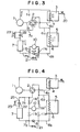
- Fig. 3 shows another embodiment of the space cooling and heating and hot water supplying apparatus in accordance with the invention, which is distinct from the embodiment shown in Fig. 1 in that a third on-off valve 21 for bypassing is connected in parallel with the expansion valve 8, and a parallel circuit of a second expansion valve 22 and a fourth on-off valve 23 for bypassing is connected to the conduit 7a connecting the outdoor heat exchanger 7 and four-way valve 2 together.
- Other parts are similar to those shown in Fig. 1 and designated by like reference characters, so that their detailed description will be omitted.
- solid line arrows indicate the directions of flow of the refrigerant in a space heating mode
- broken line arrows indicate the directions of flow of the refrigerant in a space cooling mode.
- the embodiment shown in Fig. 3 operates in the same manner as described by referring to the embodiment shown in Fig. 1 in the operation of simultaneously performing space heating and hot water supply, the operation of performing space heating without performing hot water supply, the operation of performing hot water supply without performing space heating, the operation of simultaneously performing space cooling and hot water supply and the operation of performing space cooling without performing hot water supply.
- the third on-off valve 21 is closed and the fourth on-off valve 23 is opened.
- the operation of performing hot water supply without performing space cooling will be described.
- the first on-off valve lla is opened and the second on-off valve llb is closed.
- the fourth on-off valve 23 is closed and the third on-off valve 21 is opened. At this time, the refrigerant flows in directions indicated by double broken lines.
- the refrigerant of high temperature released from the compressor 1 gives off heat in the first indoor heat exchanger 4 for hot water supply and is condensed into a liquid state, and the liquid refrigerant flows through the four-way valve 2 to the second expansion valve 22, where it has its pressure reduced.
- the refrigerant flows to the outdoor heat exchanger 7 where it absorbes heat from a heat source (such as air) and undergoes vaporization to change into gaseous refrigerant which flows through the third on-off valve 21 to the second indoor heat exchanger 6 for cooling (heating) where it is slightly super-heated before flowing through the four-way valve 2 to the compressor 1.
- a heat source such as air
- the refrigerant flows as described hereinabove, almost no cooling operation is performed by the second indoor heat exchanger 6, and freezing of the cold water in the heat accumulating tank 5 can be avoided, thereby keeping the parts from suffering damage.
- the first on-off valve lla is connected to the conduit 6b and the second on-off valve llb is connected to the conduit 7b.
- the connections of the two on-off valves lla and llb may be made as shown in Fig. 4 which illustrates a modification of the embodiment shown in Fig. 3.
- the first on-off valve lla' connected at one end thereof to the refrigerant tank 10 is connected at an opposite end thereof to the conduit 6a; and the second on-off valve llb' connected at one end thereof to the refrigerant tank 10 is connected at an opposite end thereof to the conduit 7a connecting a junction 25 of the second expansion valve 22 and the fourth on-off valve 23 to the four-way valve 2.
- the first on-off valve lla' may be located in a solid line position, and the second on-off valve llb may be located in a broken line position.
- the first on-off valve lla may be located in a broken line position and the second on-off valve llb' may be located in a solid line position.
- Other parts are similar to those which are shown in Fig. 3 and designated by like reference characters, so that their detailed description will be omitted.
- the refrigerant tank 10 shown in Fig. 4 performs the same function as the refrigerant tank 10 shown in Fig. 3 for regulating the amount of the refrigerant sealed in the refrigeration circuit.
Landscapes
- Engineering & Computer Science (AREA)
- Mechanical Engineering (AREA)
- General Engineering & Computer Science (AREA)
- Physics & Mathematics (AREA)
- Thermal Sciences (AREA)
- Chemical & Material Sciences (AREA)
- Combustion & Propulsion (AREA)
- Life Sciences & Earth Sciences (AREA)
- Sustainable Development (AREA)
- Heat-Pump Type And Storage Water Heaters (AREA)
Applications Claiming Priority (4)
| Application Number | Priority Date | Filing Date | Title |
|---|---|---|---|
| JP144883/83 | 1983-08-10 | ||
| JP14488383A JPS6036850A (ja) | 1983-08-10 | 1983-08-10 | 冷暖房給湯装置 |
| JP194055/83 | 1983-10-19 | ||
| JP19405583A JPS6086356A (ja) | 1983-10-19 | 1983-10-19 | 冷暖房給湯装置 |
Publications (3)
| Publication Number | Publication Date |
|---|---|
| EP0134015A2 true EP0134015A2 (fr) | 1985-03-13 |
| EP0134015A3 EP0134015A3 (en) | 1986-12-30 |
| EP0134015B1 EP0134015B1 (fr) | 1989-02-01 |
Family
ID=26476166
Family Applications (1)
| Application Number | Title | Priority Date | Filing Date |
|---|---|---|---|
| EP19840109370 Expired EP0134015B1 (fr) | 1983-08-10 | 1984-08-07 | Appareil de refroidissement et de chauffage d'un local et de ravitaillement en eau chaude sanitaire |
Country Status (2)
| Country | Link |
|---|---|
| EP (1) | EP0134015B1 (fr) |
| DE (1) | DE3476577D1 (fr) |
Cited By (27)
| Publication number | Priority date | Publication date | Assignee | Title |
|---|---|---|---|---|
| FR2589560A1 (fr) * | 1985-10-31 | 1987-05-07 | American Standard Inc | Circuit de refrigeration et circuit de pompe a chaleur, et procede de degivrage |
| US4685307A (en) * | 1984-07-27 | 1987-08-11 | Uhr Corporation | Residential heating, cooling and energy management system |
| WO1998058214A1 (fr) * | 1997-06-18 | 1998-12-23 | Giampaolo Bettelli | Dispositif d'air conditionne a usage domestique |
| EP0952411A1 (fr) * | 1998-04-24 | 1999-10-27 | De' Longhi S.P.A. | Machine pour chauffer ou refroidir de l'air ou de l'eau au moyen d'un frigorigène |
| WO2001055647A1 (fr) * | 2000-01-26 | 2001-08-02 | Isola Del Condizionatore S.R.L. | Conditionneur d'air a recuperation de chaleur |
| EP1312877A3 (fr) * | 2001-11-19 | 2003-11-05 | RHOSS S.p.A. | Unité frigorifique à plusieurs fonctions pour systèmes de conditionnement d'air |
| EP1467158A3 (fr) * | 2003-04-09 | 2004-12-01 | Hitachi, Ltd. | Appareil a cycle de réfrigération |
| FR2949527A1 (fr) * | 2009-08-27 | 2011-03-04 | Valeo Systemes Thermiques | Vanne pour compresseur a adsorption |
| FR2950678A1 (fr) * | 2009-09-30 | 2011-04-01 | Aldes Aeraulique | Installation de ventilation mecanique controlee de type double flux thermodynamique reversible avec production d'eau chaude sanitaire |
| EP2378210A1 (fr) * | 2010-04-19 | 2011-10-19 | Solar-Master Switzerland GmbH | Système de thermorégulation |
| FR2986860A1 (fr) * | 2012-02-14 | 2013-08-16 | Commissariat Energie Atomique | Installation thermique et procede assurant un conditionnement thermique d'un local et une production d'eau chaude sanitaire |
| WO2013142760A1 (fr) * | 2012-03-22 | 2013-09-26 | Climate Master, Inc. | Pompe à chaleur et circuit de chauffage d'eau intégrés |
| EP2360442A4 (fr) * | 2008-12-16 | 2014-06-25 | Mitsubishi Electric Corp | Dispositif d'alimentation en eau chaude de type pompe à chaleur et procédé de fonctionnement de celui-ci |
| US9383126B2 (en) | 2011-12-21 | 2016-07-05 | Nortek Global HVAC, LLC | Refrigerant charge management in a heat pump water heater |
| WO2018086418A1 (fr) * | 2016-11-14 | 2018-05-17 | 重庆美的通用制冷设备有限公司 | Système de réfrigération et dispositif de réfrigération le comprenant |
| AU2014406800B2 (en) * | 2014-09-26 | 2019-01-24 | Gree Electric Appliances, Inc, Of Zhuhai | Variable refrigerant volume system and control method thereof |
| US10345004B1 (en) | 2015-09-01 | 2019-07-09 | Climate Master, Inc. | Integrated heat pump and water heating circuit |
| EP3587954A1 (fr) | 2018-06-28 | 2020-01-01 | Electricité de France | Installation de production d'eau chaude sanitaire et procédé de pilotage de celle-ci |
| CN110762887A (zh) * | 2019-10-17 | 2020-02-07 | 广东纽恩泰新能源科技发展有限公司 | 一种多功能空气能热泵系统及其控制方法 |
| US10753661B2 (en) | 2014-09-26 | 2020-08-25 | Waterfurnace International, Inc. | Air conditioning system with vapor injection compressor |
| US10866002B2 (en) | 2016-11-09 | 2020-12-15 | Climate Master, Inc. | Hybrid heat pump with improved dehumidification |
| US10871314B2 (en) | 2016-07-08 | 2020-12-22 | Climate Master, Inc. | Heat pump and water heater |
| US10935260B2 (en) | 2017-12-12 | 2021-03-02 | Climate Master, Inc. | Heat pump with dehumidification |
| CN114562829A (zh) * | 2020-11-27 | 2022-05-31 | 苏州三星电子有限公司 | 一种带水力机组具有热回收功能的中央空调装置 |
| US11506430B2 (en) | 2019-07-15 | 2022-11-22 | Climate Master, Inc. | Air conditioning system with capacity control and controlled hot water generation |
| US11592215B2 (en) | 2018-08-29 | 2023-02-28 | Waterfurnace International, Inc. | Integrated demand water heating using a capacity modulated heat pump with desuperheater |
| US12181189B2 (en) | 2021-11-10 | 2024-12-31 | Climate Master, Inc. | Ceiling-mountable heat pump system |
Families Citing this family (3)
| Publication number | Priority date | Publication date | Assignee | Title |
|---|---|---|---|---|
| US20170211829A1 (en) | 2016-01-25 | 2017-07-27 | Sharp Kabushiki Kaisha | Optimised heat pump system |
| US20170211862A1 (en) | 2016-01-25 | 2017-07-27 | Sharp Kabushiki Kaisha | Dual temperature heat pump system |
| EP3376121A1 (fr) | 2017-03-17 | 2018-09-19 | Sharp Kabushiki Kaisha | Dispositif d'échange de chaleur et procédé de fonctionnement d'un dispositif d'échange de chaleur |
Family Cites Families (2)
| Publication number | Priority date | Publication date | Assignee | Title |
|---|---|---|---|---|
| US3366166A (en) * | 1965-07-01 | 1968-01-30 | Carrier Corp | Conditioning apparatus |
| DE2919824A1 (de) * | 1979-05-16 | 1980-11-20 | Siemens Ag | Waermepumpe |
-
1984
- 1984-08-07 DE DE8484109370T patent/DE3476577D1/de not_active Expired
- 1984-08-07 EP EP19840109370 patent/EP0134015B1/fr not_active Expired
Cited By (43)
| Publication number | Priority date | Publication date | Assignee | Title |
|---|---|---|---|---|
| US4685307A (en) * | 1984-07-27 | 1987-08-11 | Uhr Corporation | Residential heating, cooling and energy management system |
| FR2589560A1 (fr) * | 1985-10-31 | 1987-05-07 | American Standard Inc | Circuit de refrigeration et circuit de pompe a chaleur, et procede de degivrage |
| WO1998058214A1 (fr) * | 1997-06-18 | 1998-12-23 | Giampaolo Bettelli | Dispositif d'air conditionne a usage domestique |
| EP0952411A1 (fr) * | 1998-04-24 | 1999-10-27 | De' Longhi S.P.A. | Machine pour chauffer ou refroidir de l'air ou de l'eau au moyen d'un frigorigène |
| WO2001055647A1 (fr) * | 2000-01-26 | 2001-08-02 | Isola Del Condizionatore S.R.L. | Conditionneur d'air a recuperation de chaleur |
| EP1312877A3 (fr) * | 2001-11-19 | 2003-11-05 | RHOSS S.p.A. | Unité frigorifique à plusieurs fonctions pour systèmes de conditionnement d'air |
| EP1467158A3 (fr) * | 2003-04-09 | 2004-12-01 | Hitachi, Ltd. | Appareil a cycle de réfrigération |
| US8839636B2 (en) | 2008-12-16 | 2014-09-23 | Mitsubishi Electric Corporation | Heat pump water heater and operating method thereof |
| EP2360442A4 (fr) * | 2008-12-16 | 2014-06-25 | Mitsubishi Electric Corp | Dispositif d'alimentation en eau chaude de type pompe à chaleur et procédé de fonctionnement de celui-ci |
| FR2949527A1 (fr) * | 2009-08-27 | 2011-03-04 | Valeo Systemes Thermiques | Vanne pour compresseur a adsorption |
| EP2312227A1 (fr) * | 2009-09-30 | 2011-04-20 | Aldes Aeraulique | Installation de ventilation mécanique contrôlée de type double flux thermodynamique réversible avec production d'eau chaude sanitaire |
| FR2950678A1 (fr) * | 2009-09-30 | 2011-04-01 | Aldes Aeraulique | Installation de ventilation mecanique controlee de type double flux thermodynamique reversible avec production d'eau chaude sanitaire |
| EP2378210A1 (fr) * | 2010-04-19 | 2011-10-19 | Solar-Master Switzerland GmbH | Système de thermorégulation |
| US9383126B2 (en) | 2011-12-21 | 2016-07-05 | Nortek Global HVAC, LLC | Refrigerant charge management in a heat pump water heater |
| FR2986860A1 (fr) * | 2012-02-14 | 2013-08-16 | Commissariat Energie Atomique | Installation thermique et procede assurant un conditionnement thermique d'un local et une production d'eau chaude sanitaire |
| EP2629023A1 (fr) * | 2012-02-14 | 2013-08-21 | Commissariat A L'energie Atomique Et Aux Energies Alternatives | Installation thermique et procédé assurant un conditionnement thermique d'un local et une production d'eau chaude sanitaire |
| WO2013142760A1 (fr) * | 2012-03-22 | 2013-09-26 | Climate Master, Inc. | Pompe à chaleur et circuit de chauffage d'eau intégrés |
| US10753661B2 (en) | 2014-09-26 | 2020-08-25 | Waterfurnace International, Inc. | Air conditioning system with vapor injection compressor |
| US11927377B2 (en) | 2014-09-26 | 2024-03-12 | Waterfurnace International, Inc. | Air conditioning system with vapor injection compressor |
| AU2014406800B2 (en) * | 2014-09-26 | 2019-01-24 | Gree Electric Appliances, Inc, Of Zhuhai | Variable refrigerant volume system and control method thereof |
| US10317118B2 (en) | 2014-09-26 | 2019-06-11 | Gree Electric Appliances, Inc. Of Zhuhai | Variable refrigerant volume system and control method thereof |
| US11480372B2 (en) | 2014-09-26 | 2022-10-25 | Waterfurnace International Inc. | Air conditioning system with vapor injection compressor |
| US10345004B1 (en) | 2015-09-01 | 2019-07-09 | Climate Master, Inc. | Integrated heat pump and water heating circuit |
| US10871314B2 (en) | 2016-07-08 | 2020-12-22 | Climate Master, Inc. | Heat pump and water heater |
| US11448430B2 (en) | 2016-07-08 | 2022-09-20 | Climate Master, Inc. | Heat pump and water heater |
| US12181194B2 (en) | 2016-07-08 | 2024-12-31 | Climate Master, Inc. | Heat pump and water heater |
| US11435095B2 (en) | 2016-11-09 | 2022-09-06 | Climate Master, Inc. | Hybrid heat pump with improved dehumidification |
| US10866002B2 (en) | 2016-11-09 | 2020-12-15 | Climate Master, Inc. | Hybrid heat pump with improved dehumidification |
| US12181179B2 (en) | 2016-11-09 | 2024-12-31 | Climate Master, Inc. | Hybrid heat pump with improved dehumidification |
| WO2018086418A1 (fr) * | 2016-11-14 | 2018-05-17 | 重庆美的通用制冷设备有限公司 | Système de réfrigération et dispositif de réfrigération le comprenant |
| US10935260B2 (en) | 2017-12-12 | 2021-03-02 | Climate Master, Inc. | Heat pump with dehumidification |
| FR3083297A1 (fr) * | 2018-06-28 | 2020-01-03 | Electricite De France | Installation de production d'eau chaude sanitaire et procede de pilotage de celle-ci |
| EP3587954A1 (fr) | 2018-06-28 | 2020-01-01 | Electricité de France | Installation de production d'eau chaude sanitaire et procédé de pilotage de celle-ci |
| US12578124B2 (en) | 2018-08-29 | 2026-03-17 | Waterfurnace International, Inc. | Integrated demand water heating using a capacity modulated heat pump with desuperheater |
| US11592215B2 (en) | 2018-08-29 | 2023-02-28 | Waterfurnace International, Inc. | Integrated demand water heating using a capacity modulated heat pump with desuperheater |
| US11953239B2 (en) | 2018-08-29 | 2024-04-09 | Waterfurnace International, Inc. | Integrated demand water heating using a capacity modulated heat pump with desuperheater |
| US12173940B2 (en) | 2019-07-15 | 2024-12-24 | Climate Master, Inc. | Air conditioning system with capacity control and controlled hot water generation |
| US12169085B2 (en) | 2019-07-15 | 2024-12-17 | Climate Master, Inc. | Air conditioning system with capacity control and controlled hot water generation |
| US11506430B2 (en) | 2019-07-15 | 2022-11-22 | Climate Master, Inc. | Air conditioning system with capacity control and controlled hot water generation |
| CN110762887A (zh) * | 2019-10-17 | 2020-02-07 | 广东纽恩泰新能源科技发展有限公司 | 一种多功能空气能热泵系统及其控制方法 |
| CN114562829B (zh) * | 2020-11-27 | 2024-05-14 | 苏州三星电子有限公司 | 一种带水力机组具有热回收功能的中央空调装置 |
| CN114562829A (zh) * | 2020-11-27 | 2022-05-31 | 苏州三星电子有限公司 | 一种带水力机组具有热回收功能的中央空调装置 |
| US12181189B2 (en) | 2021-11-10 | 2024-12-31 | Climate Master, Inc. | Ceiling-mountable heat pump system |
Also Published As
| Publication number | Publication date |
|---|---|
| EP0134015A3 (en) | 1986-12-30 |
| DE3476577D1 (en) | 1989-03-09 |
| EP0134015B1 (fr) | 1989-02-01 |
Similar Documents
| Publication | Publication Date | Title |
|---|---|---|
| EP0134015B1 (fr) | Appareil de refroidissement et de chauffage d'un local et de ravitaillement en eau chaude sanitaire | |
| US4308042A (en) | Heat pump with freeze-up prevention | |
| CN108826536A (zh) | 具有除霜制热不停机功能的空调器装置 | |
| CN102384586A (zh) | 并联式互助除霜空气源热泵热水器 | |
| CN109282401A (zh) | 分离式热管空调及其控制方法 | |
| CN106225280A (zh) | 一种制冷或热泵系统以及一种压缩冷凝机组 | |
| CN207214503U (zh) | 空调器系统及具有其的空调器 | |
| US4722197A (en) | High-efficiency, ambient-assisted, integrated heating and cooling system | |
| CN118998846A (zh) | 一种室外机、空调器及控制方法 | |
| CN104654679B (zh) | 一种冷凝系统、风冷式空调系统和控制方法 | |
| CN111219914A (zh) | 一种冷风机热氟融霜及制冷循环系统 | |
| CN211552133U (zh) | 高效节能制冷加热控温系统 | |
| US20110209491A1 (en) | Reversible system for recovering of heat energy by sampling and transfer of calories from one or more media into one or more other such media | |
| CN221505304U (zh) | 一种空气源热泵机组 | |
| CN208720416U (zh) | 复叠式冷暖机组 | |
| CN216924801U (zh) | 用于冷冻机组的室外机、冷冻机组 | |
| CN216744681U (zh) | 一种自然冷却空调机组 | |
| CN212619487U (zh) | 一种提高宽温区应用的制冷系统过冷度装置 | |
| US20060130515A1 (en) | Refrigeration system and a method for operating such system | |
| CN217685815U (zh) | 空调器 | |
| JPS6018895B2 (ja) | 太陽熱利用ヒ−トポンプ式空気調和機 | |
| JPH11304265A (ja) | 空気調和機 | |
| JPH04257661A (ja) | 二段圧縮冷凍サイクル装置 | |
| JPS5816622Y2 (ja) | 空気調和装置 | |
| JPS60259862A (ja) | ソ−ラヒ−トポンプ装置 |
Legal Events
| Date | Code | Title | Description |
|---|---|---|---|
| PUAI | Public reference made under article 153(3) epc to a published international application that has entered the european phase |
Free format text: ORIGINAL CODE: 0009012 |
|
| 17P | Request for examination filed |
Effective date: 19840807 |
|
| AK | Designated contracting states |
Designated state(s): DE GB SE |
|
| PUAL | Search report despatched |
Free format text: ORIGINAL CODE: 0009013 |
|
| AK | Designated contracting states |
Kind code of ref document: A3 Designated state(s): DE GB SE |
|
| 17Q | First examination report despatched |
Effective date: 19871015 |
|
| GRAA | (expected) grant |
Free format text: ORIGINAL CODE: 0009210 |
|
| AK | Designated contracting states |
Kind code of ref document: B1 Designated state(s): DE GB SE |
|
| REF | Corresponds to: |
Ref document number: 3476577 Country of ref document: DE Date of ref document: 19890309 |
|
| PLBE | No opposition filed within time limit |
Free format text: ORIGINAL CODE: 0009261 |
|
| STAA | Information on the status of an ep patent application or granted ep patent |
Free format text: STATUS: NO OPPOSITION FILED WITHIN TIME LIMIT |
|
| 26N | No opposition filed | ||
| EAL | Se: european patent in force in sweden |
Ref document number: 84109370.1 |
|
| PGFP | Annual fee paid to national office [announced via postgrant information from national office to epo] |
Ref country code: SE Payment date: 19980706 Year of fee payment: 15 |
|
| PGFP | Annual fee paid to national office [announced via postgrant information from national office to epo] |
Ref country code: GB Payment date: 19980728 Year of fee payment: 15 |
|
| PGFP | Annual fee paid to national office [announced via postgrant information from national office to epo] |
Ref country code: DE Payment date: 19981029 Year of fee payment: 15 |
|
| PG25 | Lapsed in a contracting state [announced via postgrant information from national office to epo] |
Ref country code: GB Free format text: LAPSE BECAUSE OF NON-PAYMENT OF DUE FEES Effective date: 19990807 |
|
| PG25 | Lapsed in a contracting state [announced via postgrant information from national office to epo] |
Ref country code: SE Free format text: THE PATENT HAS BEEN ANNULLED BY A DECISION OF A NATIONAL AUTHORITY Effective date: 19990808 |
|
| GBPC | Gb: european patent ceased through non-payment of renewal fee |
Effective date: 19990807 |
|
| EUG | Se: european patent has lapsed |
Ref document number: 84109370.1 |
|
| PG25 | Lapsed in a contracting state [announced via postgrant information from national office to epo] |
Ref country code: DE Free format text: LAPSE BECAUSE OF NON-PAYMENT OF DUE FEES Effective date: 20000601 |