EP0134024A2 - Kraftstoffeinspritzeinrichtung - Google Patents
Kraftstoffeinspritzeinrichtung Download PDFInfo
- Publication number
- EP0134024A2 EP0134024A2 EP84109482A EP84109482A EP0134024A2 EP 0134024 A2 EP0134024 A2 EP 0134024A2 EP 84109482 A EP84109482 A EP 84109482A EP 84109482 A EP84109482 A EP 84109482A EP 0134024 A2 EP0134024 A2 EP 0134024A2
- Authority
- EP
- European Patent Office
- Prior art keywords
- intake
- pass passage
- fuel injection
- air
- disposed
- Prior art date
- Legal status (The legal status is an assumption and is not a legal conclusion. Google has not performed a legal analysis and makes no representation as to the accuracy of the status listed.)
- Granted
Links
Images


Classifications
-
- F—MECHANICAL ENGINEERING; LIGHTING; HEATING; WEAPONS; BLASTING
- F02—COMBUSTION ENGINES; HOT-GAS OR COMBUSTION-PRODUCT ENGINE PLANTS
- F02M—SUPPLYING COMBUSTION ENGINES IN GENERAL WITH COMBUSTIBLE MIXTURES OR CONSTITUENTS THEREOF
- F02M69/00—Low-pressure fuel-injection apparatus ; Apparatus with both continuous and intermittent injection; Apparatus injecting different types of fuel
- F02M69/04—Injectors peculiar thereto
- F02M69/042—Positioning of injectors with respect to engine, e.g. in the air intake conduit
- F02M69/043—Positioning of injectors with respect to engine, e.g. in the air intake conduit for injecting into the intake conduit upstream of an air throttle valve
-
- F—MECHANICAL ENGINEERING; LIGHTING; HEATING; WEAPONS; BLASTING
- F02—COMBUSTION ENGINES; HOT-GAS OR COMBUSTION-PRODUCT ENGINE PLANTS
- F02M—SUPPLYING COMBUSTION ENGINES IN GENERAL WITH COMBUSTIBLE MIXTURES OR CONSTITUENTS THEREOF
- F02M41/00—Fuel-injection apparatus with two or more injectors fed from a common pressure-source sequentially by means of a distributor
-
- F—MECHANICAL ENGINEERING; LIGHTING; HEATING; WEAPONS; BLASTING
- F02—COMBUSTION ENGINES; HOT-GAS OR COMBUSTION-PRODUCT ENGINE PLANTS
- F02M—SUPPLYING COMBUSTION ENGINES IN GENERAL WITH COMBUSTIBLE MIXTURES OR CONSTITUENTS THEREOF
- F02M51/00—Fuel-injection apparatus characterised by being operated electrically
- F02M51/02—Fuel-injection apparatus characterised by being operated electrically specially for low-pressure fuel-injection
-
- F—MECHANICAL ENGINEERING; LIGHTING; HEATING; WEAPONS; BLASTING
- F02—COMBUSTION ENGINES; HOT-GAS OR COMBUSTION-PRODUCT ENGINE PLANTS
- F02M—SUPPLYING COMBUSTION ENGINES IN GENERAL WITH COMBUSTIBLE MIXTURES OR CONSTITUENTS THEREOF
- F02M69/00—Low-pressure fuel-injection apparatus ; Apparatus with both continuous and intermittent injection; Apparatus injecting different types of fuel
- F02M69/46—Details, component parts or accessories not provided for in, or of interest apart from, the apparatus covered by groups F02M69/02 - F02M69/44
Definitions
- the present invention relates to a fuel injection apparatus and, more particularly, to a fuel injection apparatus provided with a plurality of intake tubes for supplying an air-fuel mixture to an engine having a plurality of cylinders.
- Engines having a relatively large piston displacement have a tendency to be constructed as V-engines or horizontally opposed engines for the purpose of reducing the size and weight of the engines.
- an arrangement has been employed such as that mentioned in the specification of U.K.Patent Application GB 2,082,252 A, in which a fuel injection apparatus is employed which has a plurality of intake tubes and a plurality of fuel injection valves which respectively correspond to a plurality of intake manifolds, and the intake tubes are respectively provided with throttle valves, which are adapted to be simultaneously opened or closed.
- a hot-wire type air flowmeter is employed in order to measure the quantity of air sucked into the intake tubes, and the detection portion of the air flowmeter is disposed in a by-pass passage which allows a quantity of air to pass that is proportional to the quantity of air sucked into the intake tubes.
- the fuel injection apparatus mentioned in the above-mentioned specification is arranged such that the outlets of the by-pass passage are respectively disposed inside the intake tubes but the inlets of the by-pass passage are respectively disposed outside the intake tubes. For this reason, the intake air pulsation produced by the operation of the engine is transmitted also to the by-pass passage, causing disorder of the output of the hot-wire type air flowmeter.
- a fuel injection apparatus comprising: a plurality of intake tubes each having a throttle valve; a fuel injection valve for injecting fuel into each of the intake tubes; a hot-wire type air flowmeter for measuring the quantity of intake air sucked into the intake tubes; and a by-pass passage which accommodates the detection portion of the hot-wire type air flowmeter, wherein the by-pass passage has an inlet portion for introducing the static pressure of flow of the intake air sucked into each intake tube, a central portion for passing en bloc the air introduced from each of the intake tubes and an outlet portion for discharging into each intake tube the air passing through the central portion, the detection portion of the hot-wire type air flowmeter being disposed in the central portion of the by-pass passage.
- Each of the inlets of the by-pass passage is preferably provided in the side wall of an injector holder accommodating the corresponding fuel injection valve or the side wall of the corresponding intake tube.
- FIGs. 1 and 2 A fuel injection apparatus in accordance with one embodiment of the present invention will be described hereinunder with reference to FIGs. 1 and 2.
- An intake manifold body 10 is constituted by intake manifolds 12, 14 which are divided for two systems.
- One intake manifold 12 supplies an air-fuel mixture to one group of engine cylinders, not shown, while the other intake manifold 14 similarly supplies an air-fuel mixture to another group of engine cylinders, not shown.
- An intake tube 16 is provided correspondingly to the intake manifold 12, and an intake tube 18 is provided correspondingly to the intake manifold 14.
- the intake tubes 16, 18 are respectively provided therein with throttle valves 20, 22.
- These throttle valves 20, 22 are mounted on a rotatable shaft 24 by means of respective pairs of bolts 26, 28 and 30, 32.
- a throttle sensor 34 is mounted on an end portion of the shaft 24 to detect the rotational position, angular acceleration or the like of the shaft 24.
- Injector holders 40, 42 respectively incorporating injectors 36, 38 are disposed in the respective upper portions of the intake tubes 16, 18.
- the injector holders 40, 42 are connected to the respective side walls of the intake tubes 16, 18 which are closer to the central portion therebetween through respective mounting portions 43, 44.
- the injector holders 40, 42 are respectively provided in their side surfaces (the surfaces extending coincidently with the intake air flowing direction) with a plurality of by-pass passage inlets 45, 46.
- a by-pass passage 47 is provided in the central portion between the intake tubes 16 and 18.
- the upper part of the by-pass passage 47 is communicated with the by-pass passage inlets 45, 46 through respective passages 48, 49 provided in the mounting portions 43, 44, while the lower part of the by-pass passage 47 is communicated with by-pass passage outlets 50, 52 provided in the respective side walls of the intake tubes 16, 18.
- the by-pass passage 47 is provided therein with the detection portion of a hot-wire type air flowmeter, that is, a hot wire 54.
- a body portion 55 of the hot-wire type air flowmeter which accommodates the detection circuit thereof is mounted outside the intake tubes 16, 18.
- the intake tubes 16, 18 have an integral upper side wall 58, which is provided with a collar portion 59 for mounting an air cleaner, not shown.
- An air flow rate is detected by the hot wire 54 of the air flowmeter disposed inside the by-pass passage 47, and fuel is injected from respective nozzles 56, 57 of the injectors 36, 38 in accordance with the detected air flow rate.
- an air-fuel mixture with a predetermined air-fuel ratio is supplied into the engine cylinders through the intake manifolds 12, 14.
- this embodiment has the above-described construction, even if an intake air pulsation produced by the engine operation or other cause is transmitted into the intake tubes 16, 18, the pulsation is prevented from reaching the by-pass passage 47 in which the hot wire 54 is disposed thanks to the fact that the by-pass passage inlet and outlet 45, 50 and the by-pass passage inlet and outlet 46, 52 respectively exist in the same intake tubes 16, 18. Further, the pressure waves transmitted to the by-pass passage inlets 45 and 46 act in such a manner as to be cancelled out substantially in the upper part of the by-pass passage 47. Accordingly, the output of the hot-wire type air flowmeter is such as shown in FIG. 3B and has no disorder such as that shown in FIG.
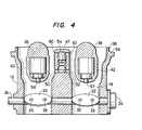
- FIG. 4 which shows another embodiment of the invention, the same reference numerals as those in FIG. 1 denote the same members or portions.
- by-pass passage inlets are respectively provided in the side walls of the injector holders 40, 42, in this embodiment by-pass passage inlets 60, 62 are respectively provided in side walls of the intake tubes 16, 18.
- the static pressures of the flows of air sucked into the intake tubes 16, 18 are introduced into the by-pass passage 47 from the respective by-pass passage inlets 60, 62, thereby making it possible to prevent the intake air pulsation from being transmitted to the detection hot wire 54 of the air flowmeter provided in the by-pass passage 47.
- the air flowmeter output is kept free from pulsations.
- the present invention having the above-described construction, makes it possible to increase the measuring accuracy of the hot-wire type air flowmeter, so that it becomes possible to effect a stable air-fuel ratio control, thereby allowing improvements in exhaust characteristics, performance, output and fuel consumption of the engine.
Landscapes
- Engineering & Computer Science (AREA)
- Chemical & Material Sciences (AREA)
- Combustion & Propulsion (AREA)
- Mechanical Engineering (AREA)
- General Engineering & Computer Science (AREA)
- Fuel-Injection Apparatus (AREA)
- Measuring Volume Flow (AREA)
- Electrical Control Of Air Or Fuel Supplied To Internal-Combustion Engine (AREA)
Applications Claiming Priority (2)
| Application Number | Priority Date | Filing Date | Title |
|---|---|---|---|
| JP145851/83 | 1983-08-09 | ||
| JP58145851A JPS6036777A (ja) | 1983-08-09 | 1983-08-09 | 燃料噴射装置 |
Publications (3)
| Publication Number | Publication Date |
|---|---|
| EP0134024A2 true EP0134024A2 (de) | 1985-03-13 |
| EP0134024A3 EP0134024A3 (en) | 1987-04-01 |
| EP0134024B1 EP0134024B1 (de) | 1989-05-24 |
Family
ID=15394555
Family Applications (1)
| Application Number | Title | Priority Date | Filing Date |
|---|---|---|---|
| EP84109482A Expired EP0134024B1 (de) | 1983-08-09 | 1984-08-09 | Kraftstoffeinspritzeinrichtung |
Country Status (6)
| Country | Link |
|---|---|
| US (1) | US4592326A (de) |
| EP (1) | EP0134024B1 (de) |
| JP (1) | JPS6036777A (de) |
| KR (1) | KR850003186A (de) |
| CA (1) | CA1202538A (de) |
| DE (1) | DE3478331D1 (de) |
Cited By (2)
| Publication number | Priority date | Publication date | Assignee | Title |
|---|---|---|---|---|
| WO1988002067A1 (en) * | 1986-09-17 | 1988-03-24 | Ford Motor Company | Fuel injection system component |
| EP0255054A3 (de) * | 1986-07-28 | 1989-05-24 | Air Sensors, Inc. | Luftmengenmesserhalterung |
Families Citing this family (2)
| Publication number | Priority date | Publication date | Assignee | Title |
|---|---|---|---|---|
| JP2694664B2 (ja) * | 1989-03-07 | 1997-12-24 | 株式会社日立製作所 | 熱線式空気流量計及び該流量計を備えた内燃機関 |
| US5756890A (en) * | 1995-11-30 | 1998-05-26 | Ford Global Technologies, Inc. | Snap mount throttle position sensor |
Family Cites Families (8)
| Publication number | Priority date | Publication date | Assignee | Title |
|---|---|---|---|---|
| GB285984A (en) * | 1926-11-24 | 1928-02-24 | Kent Ltd G | Improved means for measuring the flow of fluids |
| US3977374A (en) * | 1972-05-02 | 1976-08-31 | Paul August | Arrangement for the preparation of the fuel-air mixture for an internal combustion engine |
| US4264535A (en) * | 1978-02-24 | 1981-04-28 | Toyo Kogyo Co., Ltd. | Fuel intake system for multi-cylinder internal combustion engine |
| JPS6047462B2 (ja) * | 1978-06-02 | 1985-10-22 | 株式会社日立製作所 | 電子制御燃料噴射装置の吸入空気量計測装置 |
| DE3032067A1 (de) * | 1980-08-26 | 1982-04-15 | Robert Bosch Gmbh, 7000 Stuttgart | Kraftstoffeinspritzanlage |
| DE3032066A1 (de) * | 1980-08-26 | 1982-04-15 | Robert Bosch Gmbh, 7000 Stuttgart | Gemischbildungsanlage fuer gemischverdichtende fremgezuendete brennkraftmaschinen |
| US4347823A (en) * | 1981-02-24 | 1982-09-07 | General Motors Corporation | Throttle body injection apparatus with distribution skirt |
| DE3130626A1 (de) * | 1981-08-01 | 1983-02-17 | Robert Bosch Gmbh, 7000 Stuttgart | Vorrichtung zur messung der masse eines stroemenden mediums |
-
1983
- 1983-08-09 JP JP58145851A patent/JPS6036777A/ja active Pending
-
1984
- 1984-07-27 KR KR1019840004471A patent/KR850003186A/ko not_active Withdrawn
- 1984-08-06 US US06/638,269 patent/US4592326A/en not_active Expired - Fee Related
- 1984-08-08 CA CA000460558A patent/CA1202538A/en not_active Expired
- 1984-08-09 EP EP84109482A patent/EP0134024B1/de not_active Expired
- 1984-08-09 DE DE8484109482T patent/DE3478331D1/de not_active Expired
Cited By (3)
| Publication number | Priority date | Publication date | Assignee | Title |
|---|---|---|---|---|
| EP0255054A3 (de) * | 1986-07-28 | 1989-05-24 | Air Sensors, Inc. | Luftmengenmesserhalterung |
| WO1988002067A1 (en) * | 1986-09-17 | 1988-03-24 | Ford Motor Company | Fuel injection system component |
| EP0261855A1 (de) * | 1986-09-17 | 1988-03-30 | Ford Motor Company Limited | Bestandteil einer Brennstoffeinspritzanlage |
Also Published As
| Publication number | Publication date |
|---|---|
| DE3478331D1 (en) | 1989-06-29 |
| CA1202538A (en) | 1986-04-01 |
| KR850003186A (ko) | 1985-06-13 |
| EP0134024B1 (de) | 1989-05-24 |
| JPS6036777A (ja) | 1985-02-25 |
| US4592326A (en) | 1986-06-03 |
| EP0134024A3 (en) | 1987-04-01 |
Similar Documents
| Publication | Publication Date | Title |
|---|---|---|
| US4246874A (en) | Internal combustion engine with dual induction system and with fuel injection system to discharge fuel into primary induction system | |
| US5596969A (en) | Flow conditioning gas mass sensor | |
| US4005689A (en) | Fuel injection system controlling air/fuel ratio by intake manifold gas sensor | |
| EP2439499A1 (de) | Sensorstruktur | |
| JPS6223569A (ja) | 内燃機関の液体燃料分配方法および分配装置 | |
| US5988149A (en) | Pressure sensing system for an internal combustion engine | |
| US6014961A (en) | Internal combustion engine intake sensing system | |
| EP0134024A2 (de) | Kraftstoffeinspritzeinrichtung | |
| US4624134A (en) | Hot-wire air-flow meter | |
| SU598576A3 (ru) | Система впрыска топлива дл двигател внутреннего сгорани | |
| US6837220B2 (en) | Multiple cylinder engine | |
| US3549132A (en) | Combustion engine fuel control | |
| US2837074A (en) | Fuel injection system | |
| EP0065288B1 (de) | Kraftstoffversorgungs- oder Einspritzvorrichtung für einen mehrzylindrigen Motor | |
| JP3699226B2 (ja) | 双胴気化器 | |
| US2935053A (en) | Two stroke engines | |
| JP3812242B2 (ja) | ガスエンジンの燃料供給装置 | |
| JP4173847B2 (ja) | 内燃機関の吸気装置 | |
| US4002153A (en) | Intake system in internal combustion engine | |
| EP0138425B1 (de) | Verteilung und Dosieren von Kraftstoff | |
| JP4173834B2 (ja) | 内燃機関の吸気装置 | |
| EP0219746A1 (de) | Kraftstoffeinspritzvorrichtung | |
| US5119787A (en) | Fuel supply system for injection carburetors | |
| JP4173848B2 (ja) | 内燃機関の吸気装置 | |
| JPS58128412A (ja) | 単車用混合気供給装置 |
Legal Events
| Date | Code | Title | Description |
|---|---|---|---|
| PUAI | Public reference made under article 153(3) epc to a published international application that has entered the european phase |
Free format text: ORIGINAL CODE: 0009012 |
|
| 17P | Request for examination filed |
Effective date: 19840822 |
|
| AK | Designated contracting states |
Designated state(s): DE GB |
|
| PUAL | Search report despatched |
Free format text: ORIGINAL CODE: 0009013 |
|
| AK | Designated contracting states |
Kind code of ref document: A3 Designated state(s): DE GB |
|
| 17Q | First examination report despatched |
Effective date: 19880202 |
|
| GRAA | (expected) grant |
Free format text: ORIGINAL CODE: 0009210 |
|
| AK | Designated contracting states |
Kind code of ref document: B1 Designated state(s): DE GB |
|
| REF | Corresponds to: |
Ref document number: 3478331 Country of ref document: DE Date of ref document: 19890629 |
|
| PLBE | No opposition filed within time limit |
Free format text: ORIGINAL CODE: 0009261 |
|
| STAA | Information on the status of an ep patent application or granted ep patent |
Free format text: STATUS: NO OPPOSITION FILED WITHIN TIME LIMIT |
|
| 26N | No opposition filed | ||
| PGFP | Annual fee paid to national office [announced via postgrant information from national office to epo] |
Ref country code: GB Payment date: 19910729 Year of fee payment: 8 |
|
| PGFP | Annual fee paid to national office [announced via postgrant information from national office to epo] |
Ref country code: DE Payment date: 19910904 Year of fee payment: 8 |
|
| PG25 | Lapsed in a contracting state [announced via postgrant information from national office to epo] |
Ref country code: GB Effective date: 19920809 |
|
| GBPC | Gb: european patent ceased through non-payment of renewal fee |
Effective date: 19920809 |
|
| PG25 | Lapsed in a contracting state [announced via postgrant information from national office to epo] |
Ref country code: DE Effective date: 19930501 |