EP0134032B1 - Rouleau sous-sol compacteur - Google Patents
Rouleau sous-sol compacteur Download PDFInfo
- Publication number
- EP0134032B1 EP0134032B1 EP19840109610 EP84109610A EP0134032B1 EP 0134032 B1 EP0134032 B1 EP 0134032B1 EP 19840109610 EP19840109610 EP 19840109610 EP 84109610 A EP84109610 A EP 84109610A EP 0134032 B1 EP0134032 B1 EP 0134032B1
- Authority
- EP
- European Patent Office
- Prior art keywords
- packer
- rings
- land
- frame
- group
- Prior art date
- Legal status (The legal status is an assumption and is not a legal conclusion. Google has not performed a legal analysis and makes no representation as to the accuracy of the status listed.)
- Expired
Links
- 238000010276 construction Methods 0.000 claims description 2
- 230000008878 coupling Effects 0.000 claims 1
- 238000010168 coupling process Methods 0.000 claims 1
- 238000005859 coupling reaction Methods 0.000 claims 1
- 230000015572 biosynthetic process Effects 0.000 description 2
- 238000009826 distribution Methods 0.000 description 2
- 238000003971 tillage Methods 0.000 description 2
- 238000006243 chemical reaction Methods 0.000 description 1
- 230000005484 gravity Effects 0.000 description 1
- 238000000034 method Methods 0.000 description 1
- 238000012856 packing Methods 0.000 description 1
- 238000005192 partition Methods 0.000 description 1
- 238000007363 ring formation reaction Methods 0.000 description 1
- 239000002689 soil Substances 0.000 description 1
- 125000006850 spacer group Chemical group 0.000 description 1
- 238000003860 storage Methods 0.000 description 1
- 239000013589 supplement Substances 0.000 description 1
Images


Classifications
-
- A—HUMAN NECESSITIES
- A01—AGRICULTURE; FORESTRY; ANIMAL HUSBANDRY; HUNTING; TRAPPING; FISHING
- A01B—SOIL WORKING IN AGRICULTURE OR FORESTRY; PARTS, DETAILS, OR ACCESSORIES OF AGRICULTURAL MACHINES OR IMPLEMENTS, IN GENERAL
- A01B29/00—Rollers
- A01B29/04—Rollers with non-smooth surface formed of rotatably-mounted rings or discs or with projections or ribs on the roller body; Land packers
- A01B29/041—Rollers with non-smooth surface formed of rotatably-mounted rings or discs or with projections or ribs on the roller body; Land packers of "Cambridge"-type, i.e. the soil-pressing rings being stacked on a shaft
Definitions
- the invention relates to a single-row underground packer in an embodiment according to the preamble of claim 1.
- the invention has for its object to provide a single-row underground packer of the type specified in the preamble of claim 1 with the stability of a multi-row underground packer. This object is achieved by the underground packer according to the invention by the features specified in claim 1. With regard to further refinements, reference is made to claims 2 to 14.
- an underground packer is created that can be easily suspended and - for example at the furrow ends - can be parked without the device tipping over or experiencing any other noteworthy changes in position compared to an operating position.
- the underground packer according to the invention is ready for operation immediately with the attachment or attachment process to a towing vehicle or towing device and does not require any preparatory conversion or preparation work.
- the soil is only worked once within the working width of the device during one work cycle, whereas with multiple-row packers or other tillage devices, multiple tillage operations are carried out in direct succession during a work cycle, which is undesirable in numerous cases.
- the frame 1 consists of a frame 1, which is constructed from longitudinal struts 3, 4 and 5 aligned parallel to the direction of travel 2 and cross struts 6 and 7 running transversely to the direction of travel 2.
- the frame 1 has connection means 8.9 for a hitch or, with appropriate training, also for an attachment to a towing vehicle, for. B. an agricultural tractor.
- 1 further includes a number of mutually spaced rotatable packer rings 10, 11 which are supported on the longitudinal struts 3, 4, 5 of the frame 1.
- the packer shaft 12 is at its free ends in bearings, not shown, on the longitudinal struts 3 and 4 of the frame, i. H. both sides, stored.
- the packer shaft 13 of the second group is in turn at both ends, i. H. stored on two sides, in separate, not illustrated bearings on the longitudinal struts 4 and 5 of the frame 1.
- the axes of rotation of the packer rings 10, 11 of the two groups defined by the packer shafts 12, 13 can be aligned transversely to the direction of travel 2 in a common alignment line, but in the example according to FIG. 1 they are preferably aligned parallel to one another, but offset horizontally from one another in the direction of travel arranged so that the underground packer, despite its single-row design, offers its own stability, which is particularly advantageous when moving or converting at the end of the field.
- the groups of packer rings 10 and 11 can also be constructed from groups of packer rings of a special design, which are joined together in a shaft-free manner and will be discussed in more detail in connection with the description of FIG. 10.
- the longitudinal and transverse struts 3, 4, 5 or 6 and 7 are preferably releasably connected to one another in order to be able to produce frames of different configurations in a particularly simple and inexpensive manner.
- the longitudinal struts have the same configuration and dimension and an arrangement between the transverse struts 6 and 7, so that, on the one hand, the spacing relationships between the longitudinal struts 3, 4, 5 to one another when assembled with and the same cross struts 6, 7 is variable and on the other hand only cross struts of different length dimensions are required for different working widths and partitions. At the same time as the variability it brings, the frame design becomes cheaper.
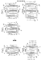
- Fig. 2 illustrates an embodiment similar to Fig. 1, but with extended cross struts 106, 107 to increase the working width, and in which the two groups of packer rings 10 and 11 are each made up of six pieces and accordingly have the same design and working width .
- each group of packer rings 10 and 11 are each arranged in a frame compartment delimited on the longitudinal side by two longitudinal struts 3, 4 and 4, 5, respectively, in the embodiments according to FIGS. 3 and 4
- the frame comprises four longitudinal struts 3, 4, 5 and 15, which accordingly limit three frame compartments on the long side.
- the cross struts 106, 107 project on both sides in the transverse direction a little above the respective outer longitudinal struts 3, 15, so that it is possible to form one or two further frame compartments for the reception of corresponding further groups of packer rings by attaching further frame struts.
- the two outer groups of packer rings 10 and 14 are in turn each supported on packer shafts 12 which are mounted in the manner described above and which define axes of rotation which are aligned with one another.
- the packer rings 11 of the middle group are supported on a packer shaft 13 which is arranged offset in the direction of travel and is mounted on the frame 1.
- the three groups of packer rings 10, 11 and 14 accordingly form a packer design that is symmetrical with respect to a vertical longitudinal center axis.
- FIG. 4 differs from that according to FIG. 3 essentially only in that the three groups of packer rings 10, 11 and 14 are each composed of three packer rings.
- An implementation of the cross struts 106 according to FIG. 3 could be used, but here again elongated cross struts 206, 207 are provided in order to offer the possibility of further enlarging the working width in spite of the already increased working width by adding further groups at the front. These could have axes of rotation that are either aligned with the axes of rotation of the packer shafts 12 or that of the packer shaft 13.
- FIGS. 5 to 9 illustrate a group of exemplary embodiments for an underground packer according to the invention, in which the overall packer rings are divided into two or three groups of packer rings 110, 111 and 114, the axes of rotation 112 and 113 of which are horizontally offset from one another.
- the frames 101 can be designed as in the examples according to FIGS. 1 to 4, instead they can also have an embodiment in which the cross struts 6, 7 or 106, 107 or 206, 207 between the longitudinal struts 3, 4 or 5 are interposed, and are only illustrated as rectangles in FIGS. 5 to 9 without reproducing constructive details.
- All groups of packer rings 110, 111 and 114 are each overhung on their longitudinal struts 3, 4 and 5, however, in such a way that the packer rings of each group are arranged distributed on both sides of the associated longitudinal strut of the frame 101.
- the detailed design of the packer rings and their storage will be discussed in connection with FIG. 10.
- the fifth has in its basic form a first group of two packer rings 110, which can be supplemented on the outside, as is indicated by dash-dotted lines, by a packer ring 110.
- the second group of packer rings 111 comprises three packer rings in the basic design of the machine, and this group can also be supplemented by adding another packer ring 111.
- the division of the packer rings within each group to the associated longitudinal strut 3, 4 is preferably chosen so that a packer ring located inside the frame compartment is provided with at most two outer packer rings. This results in a particularly stable packer design with loads that can be easily absorbed by the group bearings, which are considerably cheaper due to the ring distributions on both sides than with a fully single-sided flying bearing.
- three groups are provided, of which the first and the second group each have two packer rings 110 and 111 in the basic form, while the third group is initially formed by only one packer ring 114.
- the first group can again be added by adding another packer ring and the third group by adding up to two packer rings, so that this version comprises a variation range of five to eight packer rings.
- the first group in the basic form comprises two packer rings 110, the second group four packer rings 111 and the third group two packer rings 114, the first and the third group can be removed by one pack ring. Accordingly, the range of variation is eight to ten packer rings, but can still be increased to the range of variation six to ten if the two outer groups are initially formed by only one packer ring 110 and 114, respectively.
- the first group comprises three packer rings 110 in the basic form, the second group four packer rings 111 and the third group three packer rings 114, and the first and third groups can each again be added by adding a packer ring 110 or 114 get extended.
- the range of variation is accordingly ten to twelve packer rings or eight to twelve packer rings if the first and third groups are initially formed by only two packer rings on the inside.
- FIGS. 1 to 4 and 5 to 9 show forms of a modular system, the designs according to FIGS. 1 to 4 basically assuming that each group is supported on two sides, while the designs according to FIGS. 5 to 9 have floating bearings of the packer rings with double-sided Include distribution of the packer rings to the associated longitudinal struts.
- packer rings 10 are shown, which are provided with a hub body 10 ′ and are arranged adjacent to one another on a continuous packer shaft 12.
- the packer shaft 12 is at its visible end (as well as at its opposite end) in a ball bearing 16 on the underside of the frame struts, e.g. B. the frame strut 3, stored.
- a ball bearing 16 on the underside of the frame struts, e.g. B. the frame strut 3, stored.
- the packer shaft 12 or 13
- each has an end 12 'protruding beyond the bearing 16 which to a certain extent acts as a shaft stub for the cultivation of Packer rings z. B. 110 of the above-mentioned special training for flying or shaft-free support can serve.
- Such a supplement is particularly useful, for example, in the embodiments according to FIGS. 3 and 4.
- a packing ring 110 (or 111 or 114), which instead of a hub body has an inner ring part 110 'and a connecting part 17 connected to it.
- This connecting part comprises a support part 18 which can be screwed to the inner ring part 110' and to which an axially aligned hub sleeve 19 with fixing screw 20 is attached 110 with such connection part 17, as shown, can be placed on the projecting end 12 'of the shaft 12 or on a shaft stub 12', 12 '' projecting on both sides over the bearing 16.
- a packer ring 110 of identical construction can then be connected to the packer ring 110 provided with the connecting part 17, specifically by means of a spacer ring body 21 which is provided with flange ring parts 22 for screw connection with the inner ring parts 110 'of adjacent packer rings 110.
- packer rings 10 it is also possible to place packer rings 10 on a shaft piece 12 ', 12 ".
- connecting parts 17 instead of a hub sleeve 19 are permanently provided with a axially projecting shaft stub (not shown) which can be supported in the bearing 16, an embodiment which also makes it possible to assemble groups of packer rings, e.g. B. in the embodiments of FIGS. 1 to 4 on two sides in opposite bearings 16 on corresponding longitudinal struts of the frame.
- connection means 8, 9 are either designed to be transversely adjustable or have a plurality of connection points arranged next to one another in order to be able to relocate the point of attack to the plane of symmetry or to the center of gravity of the device.
Landscapes
- Life Sciences & Earth Sciences (AREA)
- Engineering & Computer Science (AREA)
- Mechanical Engineering (AREA)
- Soil Sciences (AREA)
- Environmental Sciences (AREA)
- Agricultural Machines (AREA)
- Rolling Contact Bearings (AREA)
- Earth Drilling (AREA)
Claims (14)
Applications Claiming Priority (2)
| Application Number | Priority Date | Filing Date | Title |
|---|---|---|---|
| DE3330998 | 1983-08-27 | ||
| DE19833330998 DE3330998A1 (de) | 1983-08-27 | 1983-08-27 | Untergrundpacker |
Publications (3)
| Publication Number | Publication Date |
|---|---|
| EP0134032A2 EP0134032A2 (fr) | 1985-03-13 |
| EP0134032A3 EP0134032A3 (en) | 1986-06-11 |
| EP0134032B1 true EP0134032B1 (fr) | 1989-03-15 |
Family
ID=6207639
Family Applications (1)
| Application Number | Title | Priority Date | Filing Date |
|---|---|---|---|
| EP19840109610 Expired EP0134032B1 (fr) | 1983-08-27 | 1984-08-13 | Rouleau sous-sol compacteur |
Country Status (2)
| Country | Link |
|---|---|
| EP (1) | EP0134032B1 (fr) |
| DE (1) | DE3330998A1 (fr) |
Families Citing this family (1)
| Publication number | Priority date | Publication date | Assignee | Title |
|---|---|---|---|---|
| DE3606992A1 (de) * | 1986-03-04 | 1987-09-10 | Rabewerk Clausing Heinrich | Pflugnachlaeufer |
Family Cites Families (12)
| Publication number | Priority date | Publication date | Assignee | Title |
|---|---|---|---|---|
| US1677127A (en) * | 1928-07-17 | op chicago | ||
| US976439A (en) * | 1910-06-17 | 1910-11-22 | Joseph T Cunningham | Rotary harrow. |
| US995592A (en) * | 1911-05-01 | 1911-06-20 | William Marshall Fulton | Machine for packing subsurface soil. |
| DE419101C (de) * | 1924-05-17 | 1925-09-19 | Otto Mueller Dipl Ing | Untergrundpacker |
| US1829605A (en) * | 1929-08-05 | 1931-10-27 | Nordstrom Abel | Roller for crushing clods |
| US2818008A (en) * | 1953-09-22 | 1957-12-31 | Kewanee Mach & Conveyor Co | Auxiliary support and disk for disk harrow gangs |
| DE1738823U (de) * | 1956-09-22 | 1957-01-31 | Franz Wiedemer | Motorisierte rasen- und gartenwalze als anbaugeraet zu einachsschleppern oder fraesen. |
| DE1143354B (de) * | 1960-08-09 | 1963-02-07 | Angelo Valdi | Egge fuer die Bodenbearbeitung |
| FR1321576A (fr) * | 1962-02-09 | 1963-03-22 | Appareil brise-mottes | |
| DE1974935U (de) * | 1967-07-28 | 1967-12-14 | Wilhelm Pluemecke Fa | Dreiteilige ackerwalze. |
| FR2417243A1 (fr) * | 1978-02-20 | 1979-09-14 | Trouve Jacques | Dispositif agraire porte rouleaux plombeurs et similaires |
| DE7810047U1 (de) * | 1978-04-05 | 1980-05-29 | Maschinenfabrik Cramer, Inh. Cramer & Soehne, 2950 Leer | Landwirtschaftliches schleppergeraet mit krumenpacker |
-
1983
- 1983-08-27 DE DE19833330998 patent/DE3330998A1/de not_active Withdrawn
-
1984
- 1984-08-13 EP EP19840109610 patent/EP0134032B1/fr not_active Expired
Also Published As
| Publication number | Publication date |
|---|---|
| DE3330998A1 (de) | 1985-03-14 |
| EP0134032A3 (en) | 1986-06-11 |
| EP0134032A2 (fr) | 1985-03-13 |
Similar Documents
| Publication | Publication Date | Title |
|---|---|---|
| DE2463444C2 (fr) | ||
| DE2336277A1 (de) | Walze, insbesondere nachlaufwalze fuer bodenbearbeitungsgeraete | |
| DE1296861B (de) | Bodenbearbeitungsmaschine | |
| DE3330997C2 (fr) | ||
| DE1156595B (de) | Schlepper mit einer Ackerschiene | |
| EP0134032B1 (fr) | Rouleau sous-sol compacteur | |
| DE692007C (de) | Ausgleichgetriebe fuer Kraftfahrzeuge | |
| DE2835635A1 (de) | Maschine zur bodenbearbeitung | |
| DE3885099T2 (de) | Bodenbearbeitungsgerät, insbesondere zum verkleinern und verdichten von erdschollen. | |
| DE3606240A1 (de) | Untersetzungsgetriebe | |
| DE2934982C2 (fr) | ||
| DE7002537U (de) | Balkenfoermiger werkzeugtraeger, insbesondere eggenbalken, fuer landwirtschaftliche maschinen | |
| DE2530105A1 (de) | Bodenbearbeitungsmaschine | |
| DE2850847C2 (de) | Bodenbearbeitungsmaschine | |
| DE2803893A1 (de) | Landwirtschaftliche bodenbearbeitungsmaschine | |
| DE60207111T2 (de) | Bodenbearbeitungswalze mit schraubenförmigen elementen | |
| DE102019205437A1 (de) | Raumoptimierte scheibenegge | |
| DE2925498A1 (de) | Bodenbearbeitungsmaschine | |
| DE2746239A1 (de) | Bodenbearbeitungsmaschine | |
| DE102019205438A1 (de) | Raumoptimiertes Bodenbearbeitungsgerät | |
| DE2713979A1 (de) | Schleppergezogene landwirtschaftliche maschine mit zwei stuetzraedern | |
| DE102019205436A1 (de) | SCHARVERSCHLEIß-REDUZIERUNG | |
| DE3516437C3 (de) | Bodenbearbeitungsmaschine, insbesondere Kreiselegge | |
| DE69102177T2 (de) | Bodenbearbeitungsmaschine. | |
| DE3432547A1 (de) | Walze, insbesondere packerwalze fuer bodenbearbeitungsmaschinen |
Legal Events
| Date | Code | Title | Description |
|---|---|---|---|
| PUAI | Public reference made under article 153(3) epc to a published international application that has entered the european phase |
Free format text: ORIGINAL CODE: 0009012 |
|
| AK | Designated contracting states |
Designated state(s): FR GB NL |
|
| PUAL | Search report despatched |
Free format text: ORIGINAL CODE: 0009013 |
|
| AK | Designated contracting states |
Kind code of ref document: A3 Designated state(s): FR GB NL |
|
| 17P | Request for examination filed |
Effective date: 19860711 |
|
| 17Q | First examination report despatched |
Effective date: 19870827 |
|
| GRAA | (expected) grant |
Free format text: ORIGINAL CODE: 0009210 |
|
| AK | Designated contracting states |
Kind code of ref document: B1 Designated state(s): FR GB NL |
|
| ET | Fr: translation filed | ||
| GBT | Gb: translation of ep patent filed (gb section 77(6)(a)/1977) | ||
| PLBE | No opposition filed within time limit |
Free format text: ORIGINAL CODE: 0009261 |
|
| STAA | Information on the status of an ep patent application or granted ep patent |
Free format text: STATUS: NO OPPOSITION FILED WITHIN TIME LIMIT |
|
| 26N | No opposition filed | ||
| PGFP | Annual fee paid to national office [announced via postgrant information from national office to epo] |
Ref country code: GB Payment date: 19910723 Year of fee payment: 8 |
|
| PGFP | Annual fee paid to national office [announced via postgrant information from national office to epo] |
Ref country code: NL Payment date: 19910831 Year of fee payment: 8 |
|
| PG25 | Lapsed in a contracting state [announced via postgrant information from national office to epo] |
Ref country code: GB Effective date: 19920813 |
|
| PG25 | Lapsed in a contracting state [announced via postgrant information from national office to epo] |
Ref country code: NL Effective date: 19930301 |
|
| GBPC | Gb: european patent ceased through non-payment of renewal fee |
Effective date: 19920813 |
|
| NLV4 | Nl: lapsed or anulled due to non-payment of the annual fee | ||
| PGFP | Annual fee paid to national office [announced via postgrant information from national office to epo] |
Ref country code: FR Payment date: 19930729 Year of fee payment: 10 |
|
| PG25 | Lapsed in a contracting state [announced via postgrant information from national office to epo] |
Ref country code: FR Effective date: 19950428 |
|
| REG | Reference to a national code |
Ref country code: FR Ref legal event code: ST |