EP0134046A2 - Machine à coudre, apte à broder - Google Patents
Machine à coudre, apte à broder Download PDFInfo
- Publication number
- EP0134046A2 EP0134046A2 EP84200681A EP84200681A EP0134046A2 EP 0134046 A2 EP0134046 A2 EP 0134046A2 EP 84200681 A EP84200681 A EP 84200681A EP 84200681 A EP84200681 A EP 84200681A EP 0134046 A2 EP0134046 A2 EP 0134046A2
- Authority
- EP
- European Patent Office
- Prior art keywords
- stitch
- sewing machine
- decorative
- stitches
- values
- Prior art date
- Legal status (The legal status is an assumption and is not a legal conclusion. Google has not performed a legal analysis and makes no representation as to the accuracy of the status listed.)
- Withdrawn
Links
Images



Classifications
-
- D—TEXTILES; PAPER
- D05—SEWING; EMBROIDERING; TUFTING
- D05B—SEWING
- D05B19/00—Program-controlled sewing machines
- D05B19/02—Sewing machines having electronic memory or microprocessor control unit
- D05B19/04—Sewing machines having electronic memory or microprocessor control unit characterised by memory aspects
- D05B19/10—Arrangements for selecting combinations of stitch or pattern data from memory ; Handling data in order to control stitch format, e.g. size, direction, mirror image
- D05B19/105—Physical layout of switches or displays; Switches co-operating with the display
-
- G—PHYSICS
- G05—CONTROLLING; REGULATING
- G05B—CONTROL OR REGULATING SYSTEMS IN GENERAL; FUNCTIONAL ELEMENTS OF SUCH SYSTEMS; MONITORING OR TESTING ARRANGEMENTS FOR SUCH SYSTEMS OR ELEMENTS
- G05B19/00—Program-control systems
- G05B19/02—Program-control systems electric
- G05B19/04—Program control other than numerical control, i.e. in sequence controllers or logic controllers
- G05B19/10—Program control other than numerical control, i.e. in sequence controllers or logic controllers using selector switches
- G05B19/102—Program control other than numerical control, i.e. in sequence controllers or logic controllers using selector switches for input of program steps, i.e. setting up sequence
- G05B19/104—Program control other than numerical control, i.e. in sequence controllers or logic controllers using selector switches for input of program steps, i.e. setting up sequence characterised by physical layout of switches; switches co-operating with display; use of switches in a special way
Definitions
- the machine according to the invention is one of the sewing machines incorrectly referred to as automatic. They are sewing machines that allow the automatic execution of sewing work with special properties of practicality or beauty. As is known, this is achieved in that the needle bar carries out oscillating movements in the transverse direction to the seam line synchronously both with the vertical upward and downward movement of the needle bar and with any repetitive changes in the web transport.
- Cam devices which are attached to sewing machines and serve the purpose of recording and providing a plurality of sewing programs inside the machine are known. All of these cam devices have a number of disadvantages. Above all, the number of programs that can be executed is limited due to the larger space requirement of the cams, since one or two cams are required for each decorative stitch pattern.
- Another disadvantage of the previous sewing machines lies in the complexity of the provision: in order for the sewing machine to be able to carry out the decorative stitch program chosen by it, the seamstress has to carry out a series of cumbersome, often strenuous, not exactly self-evident actions in an order that is difficult to remember.
- Another disadvantage is the mechanical complexity of the system, which is associated with a particular noise, inaccuracy of execution, premature wear of the machine parts, which deteriorates the appearance of the decorative stitches carried out over time.
- Sewing machines which are controlled by a logic circuit which contains a microprocessor or saves the sewing programs in ROM (Read Only Memory). See, for example, Patent Application No. 42904 A / 78. With these machines, the number of sewing programs that can be saved is practically unlimited. The sewing program is easily set by the seamstress by pressing a button without moving elements such as cams or pins. As is known, such sewing machines comprise two linear motors controlled by the logic circuit: one causes the transverse movement of the needle bar, the other controls the stitch length. However, these machines are particularly expensive.
- a cheap group consisting of a certain number of rotary cams, pins and selector elements is provided by two linear motors, a transformer and a rectifier for feeding the motors, an electronic circuit with highly developed and therefore expensive components, synchronization devices and extremely accurate position sensors, especially for stitch length adjustment, replaced.
- the invention is therefore based on the object of creating a sewing machine which, although taking advantage of the modern innovations in technology, represents an acceptable compromise between performance and costs.
- the Eachmann knows, for example, that you can perform many decorative stitches if you have the needle bar programmed to make repeated transverse movements while the transport is constant. Proof of this is the fact that sewing machines designed in this way, which are only commercially available with an automatic mechanical device for controlling the transverse positions of the needle bar.
- a first simplification of the sewing machine according to the invention is therefore the use of an electronic control only for the needle bar.
- the sewing machine only includes a linear motor, a transformer, a rectifier and an electronic circuit of smaller dimensions, as well as half the number of position sensors, which are also less expensive because the transverse movement of the needle bar may be less precise than the setting of the stitch length.
- a sewing machine designed in this way carries out a considerable number of decorative stitch patterns, but is not able to carry out the so-called elastic stitches, which are very useful and very popular with users. These are short-cycle decorative stitches, for which cyclical transport control is required. All desired elastic haptic stitches can be carried out with a single transport program, suitably linked to different programs of the needle position. However, it is obviously uneconomical to use electronic memory and control for only one program.
- the sewing machine is therefore provided with a mechanical device for automatically controlling the stitch length, which is very simple because it has only one cam.
- the invention is based on the further task of entrusting the manual actuation element for stitch adjustment with the function of choosing between at least two (better three) decorative stitch coulters, namely narrow decorative stitches, short-cycle decorative stitches with constant transport, which are also called utility stitches, and the elastic decorative stitches with automatic transport.
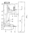
- the sewing machine shown in FIG. 1 has a frame 20, which is preferably free-arm-like in order to enable the sewing of tube material.
- a stand 21 is attached to the frame 20 and carries an arm 22 which extends above the frame 20.
- At the end of the arm 22 there is a head 23 in which the elements which serve for stitch formation are arranged, such as the swing piece 24 which carries the needle bar 25 on which the needle 26 is arranged.
- the head 23 contains other important parts, such as thread tensioner, thread tension, sewing foot, etc., which are not shown, because they are not part of the subject of the invention. For the same reason, neither the thread gripper nor the feed dog, which are contained in the frame 20, are shown. It is also understood that there is an electric motor (not shown) for driving the main shaft 27.
- the up and down movement of the needle bar is driven by an ordinary crank drive, which consists of a balanced crank 28 and the connecting rod 29.
- a handwheel 30 for controlling the needle by hand.
- the preferred position of the main electronic components is also indicated in FIG. 1, it being possible for the position sensor to be installed in the linear motor, which is connected to the flywheel 24 via the connecting rod 32.
- the electronic circuit board 33 comprises, inter alia, a transformer and a rectifier for supplying the linear motor 31, read-only memory (ROM), a logic circuit to which the input signals (input) from the control panel 34, the synchronization device and the position sensor (feedback) are fed. The output signals (output) reach the linear motor and the control panel for appropriate signaling.
- the synchronizing device allows the movement of the linear motor 31 only when the needle is located outside the fabric and consists of a rotary part 35 fastened to the main shaft 27 and a fixed part 36.
- the element sensitive to the angular position can be a "magnistor" or the like. be.
- the control panel 34 is shown in detail in FIG. 2. It contains three decorative stitch coulters, each consisting of eight decorative stitch patterns, for example.
- the first set 37 consists of narrow stitch patterns, which are also called “satin" stitches, and a constant and very short stitch length are marked.
- a warning lamp 38 alerts the seamstress that the machine is ready to perform these decorative stitches.
- a second group 39 consists of clock pulse decorative stitch patterns with a constant stitch length (medium or long) and the corresponding warning lamp 40 is arranged on the side.
- a third group 41 consists of short-cycle decorative stitch patterns with automatic transport and on the side there is the corresponding warning lamp 42.
- the seamstress selects the decorative stitch pattern from a row of buttons 43.
- a warning lamp is preferably installed in the keys 43.
- the seamstress actuates the stitch adjustment button 44.
- the stitch adjustment button 44 is attached to the sliding plate 45, which slides freely on a horizontal plane on guides, not shown, and several Tasks accomplished.
- the ball head 47 of the lever 48 is supported on the profile 46 and is articulated on the pin 49 fastened to the frame and is pressed by the spring 50 against the surface 46 of the sliding plate 45.
- the lever 48 has two prongs 51 which are operatively connected to the pin 52 fastened to the crank 53.
- the crank 53 is rigidly attached to the shaft 54 and has a second arm 55 on which the spring 56 acts in order to make the elementary pair consisting of the lever 48 and the crank 53 effective.
- the shaft 54 is the one that is usually called a stitch setting shaft in sewing machines. As is known, in almost all modern sewing machines the stitch length depends on the angular position of the stitch adjustment shaft. So you have zero feed, ie the fabric does not move, in a certain angular position of the stitch adjustment shaft. If you turn the stitch adjustment shaft in a certain direction, the stitch lengths become up to a maximum value gradually bigger. If you turn the stitch adjustment shaft in the opposite direction, you have the same stitch lengths in reverse order.
- the kinematic chain described represents a normal manual control for setting the stitch length.
- the stitch adjusting shaft 54 gradually turns clockwise due to this kinematic chain.
- a push button 57 built into the bore 58 of the stand 21 with play is connected to the lever 48 via the linkage 59. If you press the button 57 against the force of the springs 50 and 56, the lever 48 leans against the profile 61 of the connecting rods 45 via the ball head 60.
- the profile 61 and the profile 46 are essentially symmetrical, so that the positions occupied by the counterclockwise crank 53 and the positions given by the profile 46 are symmetrical. In this state, the sewing machine carries out the reverse feed.
- the stitch adjustment shaft 54 is also controlled by an automatic device.
- the lower shaft 61 (FIG. 3) of the sewing machine is generally connected to the main shaft 27 via a toothed belt and is brought into circulation by the same with the transmission ratio 1: 1.
- the shaft 61 drives the countershaft 62 via a pair of wheels 63, 64 with the transmission ratio 3: 1, so that each revolution of the countershaft 62 corresponds to three revolutions of the lower shaft 61.
- a cam disk 65 is arranged on the countershaft 62.
- a wedge 66 makes them rotatable with the shaft 62 without preventing their axial displacement for switching on and off.
- the tracer pin 67 acts, which, via a flat four-bar linkage, consists of the moving crank 68 attached to the tracer pin 67, of the connecting rod pull rod 69 and of the there is a crank 70, transmits a programmed pendulum movement to the stitch adjustment shaft 54.
- the contact between the stylus 67 and cam 65 is secured by the spring 56.
- the pin 71 is attached to the frame 20, while the pins 72, 73 are movable and ensure the relative movement between the parts.
- the automatic device described above is switched on and off via a kinematic chain which receives the movement from the profile surface 74 of the plate 45 on which the rung 75 of the lever 76 rests.
- the lever 76 and the lower lever 78 are attached to the standing spindle 77.
- the end member 79 of the lever 78 touches the fork 80, which consists of two parallel parts 81 encompassing the cam disk 65 and of the sleeve 82 arranged on the pin 83 of the frame 20.
- a rung 84 prevents the fork 80 from rotating about the pin 83, but allows it to be adjusted.
- a spring 85 actuates all the elementary pairs described.
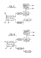
- FIGS. 6, 7, 8 and 9 show a general circuit diagram of the possibilities of the sewing machine.
- Two drive chains start from a control panel 34: a drive chain 86 for the transverse movements of the needle bar controlled by an electronic logic circuit 33 and a drive chain 87 for the stitch length controlled by a mechanical system.
- the read-only memory 88 for the needle positions is divided into two parts A and B, which can be selected by a selector 89.
- a variant of the device in question provides three further settings in order to increase the number of possible decorative stitch patterns (FIG. 15). Instead of the sensitive ele This variant 97 provides up to three sensitive elements 98, 99, 100 which are arranged at 120 ° around the shaft 62.
- FIGS. 16 and 17 show the new decorative stitch patterns that can be carried out as a result.
- the decorative stitch pattern according to FIG. 10 changes into the decorative stitch pattern 16a) when the automatic transport is switched on, if the start of the program is determined, for example, by the synchronization device 98., Into the decorative stitch pattern 16b), if the synchronization device 99 is used, and finally into the decorative stitch pattern 16c) when the synchronization device 100 is used.
Landscapes
- Engineering & Computer Science (AREA)
- Computer Hardware Design (AREA)
- Microelectronics & Electronic Packaging (AREA)
- Textile Engineering (AREA)
- Physics & Mathematics (AREA)
- General Physics & Mathematics (AREA)
- Automation & Control Theory (AREA)
- Sewing Machines And Sewing (AREA)
Applications Claiming Priority (2)
| Application Number | Priority Date | Filing Date | Title |
|---|---|---|---|
| IT42913/83A IT1062704B (it) | 1983-05-17 | 1983-05-17 | Macchina per cucire atta all'esecuzione di ricami |
| IT4291383 | 1983-05-17 |
Publications (2)
| Publication Number | Publication Date |
|---|---|
| EP0134046A2 true EP0134046A2 (fr) | 1985-03-13 |
| EP0134046A3 EP0134046A3 (fr) | 1985-11-27 |
Family
ID=11254677
Family Applications (1)
| Application Number | Title | Priority Date | Filing Date |
|---|---|---|---|
| EP84200681A Withdrawn EP0134046A3 (fr) | 1983-05-17 | 1984-05-14 | Machine à coudre, apte à broder |
Country Status (2)
| Country | Link |
|---|---|
| EP (1) | EP0134046A3 (fr) |
| IT (1) | IT1062704B (fr) |
Cited By (1)
| Publication number | Priority date | Publication date | Assignee | Title |
|---|---|---|---|---|
| EP0753614A1 (fr) * | 1995-07-14 | 1997-01-15 | Fritz Gegauf Ag Bernina-Nähmaschinenfabrik | Procédé pour la configuration de la mémoire de programme d'une machine à coudre électronique, machine à coudre pour la mise en oeuvre de ce procédé et application de la machine à coudre |
Family Cites Families (3)
| Publication number | Priority date | Publication date | Assignee | Title |
|---|---|---|---|---|
| DE905915C (de) * | 1951-04-05 | 1954-03-08 | Emil Woeckel | Steuerungsgetriebe |
| US4147118A (en) * | 1977-11-14 | 1979-04-03 | The Singer Company | Combined electronic and mechanical pattern control for a sewing machine |
| US4184441A (en) * | 1979-04-19 | 1980-01-22 | The Singer Company | Electronically controlled household sewing machine having patch sewing capability |
-
1983
- 1983-05-17 IT IT42913/83A patent/IT1062704B/it active
-
1984
- 1984-05-14 EP EP84200681A patent/EP0134046A3/fr not_active Withdrawn
Cited By (2)
| Publication number | Priority date | Publication date | Assignee | Title |
|---|---|---|---|---|
| EP0753614A1 (fr) * | 1995-07-14 | 1997-01-15 | Fritz Gegauf Ag Bernina-Nähmaschinenfabrik | Procédé pour la configuration de la mémoire de programme d'une machine à coudre électronique, machine à coudre pour la mise en oeuvre de ce procédé et application de la machine à coudre |
| US5899153A (en) * | 1995-07-14 | 1999-05-04 | Fritz Gegauf Ag Bernina-Nahmaschinenfabrik | Process for the organization of the memory of an electronic sewing machine, and sewing machine |
Also Published As
| Publication number | Publication date |
|---|---|
| IT1062704B (it) | 1984-10-31 |
| IT8342913A0 (it) | 1983-05-17 |
| EP0134046A3 (fr) | 1985-11-27 |
Similar Documents
| Publication | Publication Date | Title |
|---|---|---|
| DE2906718C2 (de) | Haushaltsnähmaschine | |
| DE2702488C2 (de) | Elektrische Zick-Zack-Nähmaschine | |
| DE3235121C2 (de) | Nähmaschine mit einer elektronischen Steuereinrichtung | |
| DE2943664C2 (de) | Elektronische Nähmaschine | |
| DE3018886A1 (de) | Einrichtung zur vereinfachung der einstellung und ausruestung an einer naehmaschine | |
| DE3337747A1 (de) | Stickeinrichtung fuer eine elektronische naehmaschine | |
| DE2836728C2 (fr) | ||
| DE3304041C2 (fr) | ||
| DE2502443A1 (de) | Naehmaschine, insbesondere zierstichnaehmaschine | |
| DE2853203C2 (fr) | ||
| DE2709087A1 (de) | Naehmaschine | |
| EP0134046A2 (fr) | Machine à coudre, apte à broder | |
| DE3519849C1 (de) | Blindstichnaehmaschine | |
| DE7035449U (de) | Naehmaschine. | |
| DE1760435C3 (fr) | ||
| DE1924219A1 (de) | Automatische Naeh- und Stickmaschine | |
| DE1903608A1 (de) | Automatische Vorrichtung zum Zufuehren von Knoepfen verschiedener Art fuer Knopfannaehmaschinen | |
| CH677680A5 (fr) | ||
| DE3817599C2 (fr) | ||
| DE2828083A1 (de) | Naehmaschine | |
| DE2945774C2 (de) | Nähmaschine für Musternähbetrieb und Geradstichbetrieb | |
| DE4225846C1 (de) | Steuerung oder Regelung für die Einstellung und/oder den Ablauf von Programmen, insbesondere Waschprogrammen bei Waschmaschinen | |
| CH660890A5 (de) | Verfahren und naehmaschine zur herstellung von naehmustern. | |
| DE2205379A1 (de) | Vorrichtung zur automatischen Ausführung von Zierstichen bei Nähmaschinen | |
| AT237418B (de) | Nähmaschine zum Ausführen von Ziernähten |
Legal Events
| Date | Code | Title | Description |
|---|---|---|---|
| PUAI | Public reference made under article 153(3) epc to a published international application that has entered the european phase |
Free format text: ORIGINAL CODE: 0009012 |
|
| AK | Designated contracting states |
Designated state(s): CH DE FR GB LI SE |
|
| RAP1 | Party data changed (applicant data changed or rights of an application transferred) |
Owner name: NECCHI SOCIETA PER AZIONI |
|
| RIN1 | Information on inventor provided before grant (corrected) |
Inventor name: BIANCHI, NEREO |
|
| PUAL | Search report despatched |
Free format text: ORIGINAL CODE: 0009013 |
|
| AK | Designated contracting states |
Designated state(s): CH DE FR GB LI SE |
|
| 17P | Request for examination filed |
Effective date: 19860207 |
|
| 17Q | First examination report despatched |
Effective date: 19870511 |
|
| STAA | Information on the status of an ep patent application or granted ep patent |
Free format text: STATUS: THE APPLICATION IS DEEMED TO BE WITHDRAWN |
|
| 18D | Application deemed to be withdrawn |
Effective date: 19870921 |
|
| RIN1 | Information on inventor provided before grant (corrected) |
Inventor name: BIANCHI, NEREO |