EP0134075A1 - Kimme - Google Patents
Kimme Download PDFInfo
- Publication number
- EP0134075A1 EP0134075A1 EP84303808A EP84303808A EP0134075A1 EP 0134075 A1 EP0134075 A1 EP 0134075A1 EP 84303808 A EP84303808 A EP 84303808A EP 84303808 A EP84303808 A EP 84303808A EP 0134075 A1 EP0134075 A1 EP 0134075A1
- Authority
- EP
- European Patent Office
- Prior art keywords
- rear sight
- threaded
- ear
- sight
- head
- Prior art date
- Legal status (The legal status is an assumption and is not a legal conclusion. Google has not performed a legal analysis and makes no representation as to the accuracy of the status listed.)
- Withdrawn
Links
- 210000005069 ears Anatomy 0.000 claims description 12
- 238000007373 indentation Methods 0.000 description 3
- 238000010586 diagram Methods 0.000 description 2
- 230000004048 modification Effects 0.000 description 2
- 238000012986 modification Methods 0.000 description 2
- 230000002093 peripheral effect Effects 0.000 description 2
- 241000519995 Stachys sylvatica Species 0.000 description 1
- 238000004519 manufacturing process Methods 0.000 description 1
- 239000003973 paint Substances 0.000 description 1
Images
Classifications
-
- F—MECHANICAL ENGINEERING; LIGHTING; HEATING; WEAPONS; BLASTING
- F41—WEAPONS
- F41G—WEAPON SIGHTS; AIMING
- F41G1/00—Sighting devices
- F41G1/06—Rearsights
- F41G1/16—Adjusting mechanisms therefor; Mountings therefor
- F41G1/26—Adjusting mechanisms therefor; Mountings therefor screw
Definitions
- the present invention generally relates to a weapon sighting assembly and, more particularly, to a rear sight for a weapon, such as a rifle, pistol, machine gun and the like.
- a typical sighting assembly for such a weapon generally referred to as a gun, consists of a front sight and a rear sight.
- the front sight is typically blade-like, often in the shape of a small diameter cylinder which is sometimes tapered so that its top is of minimal diameter. The height of the top is adjustable for ranging purposes.
- the rear sight is typically in the shape of a block with a V-shaped or U-shaped groove. The gun user uses these sights by aligning the top of the front sight with the top of the groove and centered therein. The rear sight is slidable to the right or left for course alignment.
- the present invention is directed to a new improved rear sight which consists of a minimum number of easily machinable parts.
- the present invention may be described as, a rear sight for use with a front sight on a gun comprising:
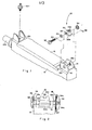
- Fig. 1 is an expanded isometric view primarily of the top of a gun 12, its barrel 12b, its front sight 12f and its rear sight 10, while Fig. 2 is a side back view of the gun and the rear sight 10.
- the prior art rear sight 10 for gun 12 e.g. a submachine gun
- the rear sight 10 may be thought of as consisting of a lead screw 20 which extends through clearance openings 14a and 15a in the two ears.
- a sight block 22 which threadably engages the threads of the screw.
- the sight block has a bottom side 22b which just clears the gun's top side 16 while its top side 22t has a U-shaped slot 30. It is this slot which serves as the sight with which the front sight 12f is being aligned. The latter is threadably engageable in a threaded hole 12t for range adjustment.
- a head 32 beyond ear 14 terminates one end of the screw 20, while a locking washer 34 is locked to and terminates the other end of the screw beyond ear 15 by means of locking pin 36.
- a spring washer 35 biases the head 32 away from ear 14 thus urging washer 34 toward ear 15.
- the locking washer 34 is provided with indentations or slots 34x while a clip element 37, which is fixedly attached to ear 15 has perturbations extending therefrom. These perturbations when extending into slots 34x produce relatively secure locked positions for the screw 20.
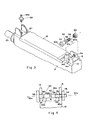
- Figs. 3 and 4 are similar to Figs. 1 and 2 in connection with which the prior art was described.
- Fig. 5 is an enlarged view of part of the sight. Therein elements like those previously described are designated by like numerals.
- the novel rear sight unit essentially consists at most of two parts. They are a bolt-like element 50, hereafter simply referred to as bolt 50, which has a head 52 at one end.
- the bolt may be thought of as consisting of two parts or portions which successively extend from head 52 to the bolt's opposite end 54.
- the first portion which extends from the head toward end 54 is designated by 50a, and the second portion 50b extends from portion 50a to end 54.
- Portion 50a is cylindrically shaped and its outer periphery is not threaded. Its diameter is designated by D1 (see Figs. 4 and 5).
- Bolt portion 50b is of reduced diameter D2, i.e. D1>D2 and is threaded as designated by 56.
- the total length of bolt 50 i.e. portions 50a and 50b is greater than the distance between the outer faces of the ears 14 and 15.
- the diameter of opening 14a in ear 14 is slightly greater than D1, to provide some clearance for the bolt 50 to extend therethrough.
- opening 15a in ear 15 it is a threaded opening whose threads engage threads 56 on the bolt portion 50b.
- the distance between the ears' outer faces is less than the total length of the bolt 50 so that the end of the latter's threaded portion 50b can be threaded through opening 15a in ear 15 as shown in Figs. 4 and 5, and extend therethrough, while the head 52 clears ear 14.
- a nut 58 is used to lock the bolt 50 in any selected fixed position.
- a radial groove or recess 60 is formed in the non-threaded cylindrical portion 50a. It is this recess which acts as the rear sight.
- the recess when viewed above (or below) the bolt longitudinal 50x is shown U-shaped. Clearly its depth, designated R, is less than the bolt's radius, i.e. it is less than (D1)/2, otherwise the bolt would be cut through.
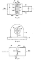
- the recess width, designated by W it is chosen to be wide enough to form an adequate sight so that the front sight 12f could be aligned between its side walls 60a and 60b. (See Fig. 5). More particularly, the top or tip of the front sight is aligned with the top of the recess 60, as shown in Fig. 5, which as stated is an enlarged, side view of a section of the bolt which includes the recess 60.
- the novel sight of the invention is an easily adjustable rear sight consisting of at least one part which is the unique bolt with the sight forming recess. Preferably however it also includes the locking nut 58 in order to secure the bolt in any chosen rotational position.
- the degree of rotation of the bolt and thus the lateral movement of the sight 60 may be indicated by providing one or more slots 52s in head 52 as shown in Figs. 3 and 6, preferably painted with a bright color, e.g. white and a corresponding marking 14m on the ear 14.
- portion 50b of bolt 50 may be of the same diameter as that of section 50a. That is, in general D2 ⁇ Dl. D2 should not be greater than D1. Otherwise the bolt would not be able to pass through opening 14a in ear 14, unless the opening 14a were made much larger than D1. However, the opening 14a should be only slightly greater than D1 just enough to clear the entrance of the bolt, yet secure portion 50a therein. Also, if desired portion 50a, herebefore described as having an unthreaded peripheral surface, may be threaded.
- the rear sight forming recess 60 it may assume other shapes than the inwardly directed recess about the entire bolt periphery.
- one or more slots of selected shapes may be formed in a direction perpendicular to axis 50x to provide individual sight forming recesses, as shown in Fig. 7.
- a rear sight formed by 60A designates an inwardly directed slot from the bolt's periphery which is U-shaped
- 60B designates an opposite rear sight which is V-shaped
- 60C designates a through hole extending perpendicular to axis 50x. It can serve as a pin hole sight for initial sighting. If desired another hole, transverse to hole 60C, and designated by dashed lines 60D may be formed.
- a 180° rotation of bolt 50 is required to switch between sights 60A and 60B. If desired more inward slots, perpendicular to axis 50x oriented less than 180° apart, may be formed.
- a radial recess of preselected shape is intended to include any recess perpendicular to the bolt axis 50x through which one can see from one side of the bolt to the other.
- the rear sight may include one or more of the recesses shown in Fig. 7.
- the rear sight can include only the bolt 50 without the nut 58, but preferably with it, one may form the sight with more parts without departing from the spirit of the invention. Consequently, it is intended that the claims be interpreted to cover such modifications and equivalents.
Landscapes
- Physics & Mathematics (AREA)
- Optics & Photonics (AREA)
- Engineering & Computer Science (AREA)
- General Engineering & Computer Science (AREA)
- Connection Of Plates (AREA)
- Dowels (AREA)
Applications Claiming Priority (2)
| Application Number | Priority Date | Filing Date | Title |
|---|---|---|---|
| IL69516A IL69516A0 (en) | 1983-08-18 | 1983-08-18 | Rear-sight for weapon a rear-sight for a weapon |
| IL69516 | 1983-08-18 |
Publications (1)
| Publication Number | Publication Date |
|---|---|
| EP0134075A1 true EP0134075A1 (de) | 1985-03-13 |
Family
ID=11054471
Family Applications (1)
| Application Number | Title | Priority Date | Filing Date |
|---|---|---|---|
| EP84303808A Withdrawn EP0134075A1 (de) | 1983-08-18 | 1984-06-06 | Kimme |
Country Status (3)
| Country | Link |
|---|---|
| US (1) | US4536966A (de) |
| EP (1) | EP0134075A1 (de) |
| IL (1) | IL69516A0 (de) |
Cited By (1)
| Publication number | Priority date | Publication date | Assignee | Title |
|---|---|---|---|---|
| WO2000050834A1 (en) * | 1999-02-23 | 2000-08-31 | Cbj Tech Ab | Sight |
Families Citing this family (5)
| Publication number | Priority date | Publication date | Assignee | Title |
|---|---|---|---|---|
| US4837937A (en) * | 1988-08-01 | 1989-06-13 | Harold Hasselbusch | Adjustable rear sight unit for a gun |
| US5481818A (en) * | 1994-12-09 | 1996-01-09 | Williams Gunsight Company | Gun sight mounting system |
| US7946074B2 (en) * | 2007-08-10 | 2011-05-24 | William Joseph Nemec | Machine gun sighting system |
| US20110308133A1 (en) * | 2010-06-16 | 2011-12-22 | William Joseph Nemec | Enhanced Accuracy Gun Iron Sighting System |
| US9151575B2 (en) * | 2013-07-26 | 2015-10-06 | Robert Harold Pereira | Firearm accessory rail and method of attachment |
Citations (2)
| Publication number | Priority date | Publication date | Assignee | Title |
|---|---|---|---|---|
| CH82994A (de) * | 1919-02-15 | 1920-04-01 | Eugen Remensberger | Visierkimmenträger zur seitlichen Verschiebung der Kimme für Hand- und Faust-Feuerwaffen |
| US3792534A (en) * | 1972-03-13 | 1974-02-19 | C Lowe | Firearm rear sight |
Family Cites Families (2)
| Publication number | Priority date | Publication date | Assignee | Title |
|---|---|---|---|---|
| DE141708C (de) * | ||||
| US1150791A (en) * | 1915-04-15 | 1915-08-17 | Marlin Firearms Co | Gun-sight. |
-
1983
- 1983-08-18 IL IL69516A patent/IL69516A0/xx unknown
-
1984
- 1984-06-06 EP EP84303808A patent/EP0134075A1/de not_active Withdrawn
- 1984-06-28 US US06/625,653 patent/US4536966A/en not_active Expired - Fee Related
Patent Citations (2)
| Publication number | Priority date | Publication date | Assignee | Title |
|---|---|---|---|---|
| CH82994A (de) * | 1919-02-15 | 1920-04-01 | Eugen Remensberger | Visierkimmenträger zur seitlichen Verschiebung der Kimme für Hand- und Faust-Feuerwaffen |
| US3792534A (en) * | 1972-03-13 | 1974-02-19 | C Lowe | Firearm rear sight |
Cited By (2)
| Publication number | Priority date | Publication date | Assignee | Title |
|---|---|---|---|---|
| WO2000050834A1 (en) * | 1999-02-23 | 2000-08-31 | Cbj Tech Ab | Sight |
| US6615530B2 (en) | 1999-02-23 | 2003-09-09 | Cbj Tech Ab | Sight |
Also Published As
| Publication number | Publication date |
|---|---|
| IL69516A0 (en) | 1985-07-31 |
| US4536966A (en) | 1985-08-27 |
Similar Documents
| Publication | Publication Date | Title |
|---|---|---|
| US4097061A (en) | Ski insert for anchoring a ski binding screw in a ski | |
| US5428915A (en) | Detachable sight mount with elevation adjustment | |
| US4283163A (en) | Cutting tool with replaceable edge cutting bit | |
| US4691442A (en) | Sight system for a firearm | |
| US4799325A (en) | Auxiliary rifle sight | |
| CA2265156A1 (en) | Anti-cross threading fastener | |
| EP0134075A1 (de) | Kimme | |
| US4873779A (en) | Scope mount base for a black powder rifle | |
| GB2196082A (en) | Self aligning screw | |
| US2548031A (en) | Telescope mount with snap rings | |
| US5428901A (en) | Bow sight mount | |
| ATE226693T1 (de) | Schraube mit einer selbstbohrenden spitze | |
| US4455865A (en) | Method and device for locating a fixed point of reference relative to a predetermined segment of rotary member | |
| US20020026196A1 (en) | Device for inserting and removing a bone nail | |
| EP0123220A3 (de) | Werkzeugmaschinenspindel mit hierzu passendem Werkzeughalter | |
| US5133142A (en) | Multi-caliber firearm | |
| ES2136173T3 (es) | Tuerca de bloqueo y procedimiento de fabricacion de la misma. | |
| US4512698A (en) | Holding mechanism, in particular for ski bindings | |
| US4671716A (en) | Locking screw for the adjustable connection of a hinge strap | |
| ES2190005T3 (es) | Cañon de arma. | |
| RU2038567C1 (ru) | Прицел для спортивного оружия | |
| US3377906A (en) | Thread-forming tool | |
| PT942181E (pt) | Prendedor de roscar anti-cruzamento | |
| KR840007454A (ko) | 나 사 | |
| US4477979A (en) | Gun sight |
Legal Events
| Date | Code | Title | Description |
|---|---|---|---|
| PUAI | Public reference made under article 153(3) epc to a published international application that has entered the european phase |
Free format text: ORIGINAL CODE: 0009012 |
|
| AK | Designated contracting states |
Designated state(s): DE FR GB IT NL |
|
| 17P | Request for examination filed |
Effective date: 19850426 |
|
| RAP1 | Party data changed (applicant data changed or rights of an application transferred) |
Owner name: THE STATE OF ISRAEL MINISTRY OF DEFENCE ISRAEL MIL |
|
| 17Q | First examination report despatched |
Effective date: 19861022 |
|
| STAA | Information on the status of an ep patent application or granted ep patent |
Free format text: STATUS: THE APPLICATION IS DEEMED TO BE WITHDRAWN |
|
| 18D | Application deemed to be withdrawn |
Effective date: 19870303 |
|
| RIN1 | Information on inventor provided before grant (corrected) |
Inventor name: ENGEL, ISAAC |