EP0134095A1 - Plattformzur kippbaren Aufnahme von Behältern - Google Patents
Plattformzur kippbaren Aufnahme von Behältern Download PDFInfo
- Publication number
- EP0134095A1 EP0134095A1 EP84305021A EP84305021A EP0134095A1 EP 0134095 A1 EP0134095 A1 EP 0134095A1 EP 84305021 A EP84305021 A EP 84305021A EP 84305021 A EP84305021 A EP 84305021A EP 0134095 A1 EP0134095 A1 EP 0134095A1
- Authority
- EP
- European Patent Office
- Prior art keywords
- base
- support
- container
- springs
- tiltable platform
- Prior art date
- Legal status (The legal status is an assumption and is not a legal conclusion. Google has not performed a legal analysis and makes no representation as to the accuracy of the status listed.)
- Granted
Links
- 230000006835 compression Effects 0.000 claims abstract 6
- 238000007906 compression Methods 0.000 claims abstract 6
- 239000000725 suspension Substances 0.000 claims description 4
- 239000000463 material Substances 0.000 description 11
- 230000005484 gravity Effects 0.000 description 3
- 238000007599 discharging Methods 0.000 description 2
- 238000000605 extraction Methods 0.000 description 2
- 229920000426 Microplastic Polymers 0.000 description 1
- 230000008602 contraction Effects 0.000 description 1
- 230000007423 decrease Effects 0.000 description 1
- 230000000694 effects Effects 0.000 description 1
- 235000013312 flour Nutrition 0.000 description 1
- 239000008187 granular material Substances 0.000 description 1
- 229920001903 high density polyethylene Polymers 0.000 description 1
- 239000007788 liquid Substances 0.000 description 1
- 238000004519 manufacturing process Methods 0.000 description 1
- 239000012254 powdered material Substances 0.000 description 1
- 230000001737 promoting effect Effects 0.000 description 1
Images


Classifications
-
- B—PERFORMING OPERATIONS; TRANSPORTING
- B65—CONVEYING; PACKING; STORING; HANDLING THIN OR FILAMENTARY MATERIAL
- B65G—TRANSPORT OR STORAGE DEVICES, e.g. CONVEYORS FOR LOADING OR TIPPING, SHOP CONVEYOR SYSTEMS OR PNEUMATIC TUBE CONVEYORS
- B65G65/00—Loading or unloading
- B65G65/23—Devices for tilting and emptying of containers
Definitions
- This invention relates to a support means for a container to facilitate the discharge of materials therefrom.
- the invention provides a tiltable platform having a base, a support for the bottom of a container, releasable latching means to pivotally interconnect the base and the support and load compressible resilient suspension means disposed between the base and the support and which will when the latching means is operative bias the support and the bottom of a container mounted thereon into an angular relationship with the horizontal and which when the latching means is inoperative bias them towards a horizontal condition.
- a platform 1 which can be of any suitable form for example a simple rectangular frame, with a pair of aligned spigots 2 extending from opposite sides of the platform.
- an upstanding stop means 3 which may be in the form of lugs or a bar against which a base corner of a container mounted on the platform 1 will bear during the discharge of the container.
- the base 5 which can be of any suitable form for example a simple rectangular frame, has two track forming brackets 6 at opposite sides and the spigots 2 are slidably mounted in the tracks of the brackets 6.
- the rods 9 are pivotally connected to the spring sockets 7 and the upper spring sockets 4 are pivotally supported on the platform,
- the container C has a discharge means adjacent the bottom edge of the front side of the container.
- the springs 8 When a full container C is loaded onto the platform 1 it will cause the springs 8 to be compressed and the platform to come to rest on stop blocks 10 on the base 5 and the spigots 2 to come to rest on the stop blocks 11 on the base 5.
- In descending the spigots 2 would engage the upper sloping faces 12 of hooked upper ends of arms 13 pivoted at 14 to the base and interconnected through arm extensions 15.
- the tilting platform will usually be located adjacent an industrial process, where it is constantly discharging a given product from containers into a hopper or the like, it is possible to design the springs so that after the container has been emptied to a gien level the stored energy in the springs 8 is sufficient to commence elevation of the rear end of the platform 1.
- the upper spring sockets will move upwardly within the limits imposed by the extension limiting rods 9 to produce the configuration shown in Fig.3 which is the designed maximum incline for the illustrated arrangement.
- the arrangement is particularly suitable for liquids but can be used for granular or powdered materials.
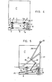
- Fig.4 The arrangement shown in Fig.4 is similar to that shown in Figs. 1 to 3 except that the springs 8.are located more to the rear of the platform and springs 16, weaker than springs 8, are located in spring sockets 4a and 7a adjacent the brackets 6.
- the brackets 6 are formed to provide housings for the springs 16 which are disposed between the spigots 2 and the base 5.
- the springs 16 need only be strong enough to maintain the front end of the platform 1 elevated when the container is empty, and in the case of Figs.5 to 7 maintain the spigots at the upper ends of the tracks in the brackets 6 when the container is empty.
- the springs 8 must however be strong enough to tilt the platform when the container is still partly filled.
- the platform 1 has additional features. These include a bag extractor of the type covered by my Australian patent 531154 and includes corner support columns 17 in place of the lugs 3 and diagonal braces 18 connecting the columns 17 to the platform 1.
- An arch member having a top tie roller 19 and arms 20 pivotally connected at 21 on the braces 18 extends over the container C. Angled extensions 22 of the arms 20 are respectively connected by springs 23 to two spaced apart arms 24 pivotally connected at first ends at 25 to the base 5.
- the arms 24 are interconnected by a bar 26 and the other ends of the arms 24 are connected through links 27 to the'underside of the platform 1.
- the bag extractor is for the elevation and discharge promotional movement of a plastic liner bag used in the container to house in a sterile manner material transported in the container, such as powdered foodstuffs.
- the liner bag has a top tail T which is pulled over the roller 19 when the arms 20 are moved to the dotted position shown in Fig.6 and the tail T is tied down.
- the movement of the arms 20 causes the springs 23 to be tensioned.
- Discharge of the material in the liner bag commences through the bag nose BN extending though an opening in the lower front side of the container C normally covered by the hinged door D.
- the rear springs 8 will cuase the platform to tilt when a predetermined amount of material has been discharged from the container thereby facilitating the gravity discharge of material from the liner bag.
- the springs 23 are designed to be almost in their collapsed state when the Fig.6 configuration exists.
- the arch arms 20 are moved to the dotted position )Fig.6) and this will tension the springs 23 somewhat.
- the bag tail T is connected to the container and emptying commences.
- the spigots 2 are held in the down position by the hooked members and the links 27 connected to the arms 24 prevent them from moving from their lowered position illustrated in Figs.6 and 7.
- the anchor point of the springs 23 to the arm extensions 22 moves away from the bar 26 which results in the springs being further stretched.
- the energy now stored in the springs 23 is sufficient to ensure commencement of bag extraction when the major extractive force is required i.e. when the container is tilted and has a large amount of material remaining therein.
- the springs 23 are able to be stretched by hand to achieve the dotted position in Fig.6, because of their nominal stretched condition, but have energy storing additional stretch applied when required, i.e. when the container tilts and the bag needs extraction.
- Another aspect is that when the spigots 2 are released by the hooked members the upthrust of the springs 16 is supplemented by the contraction force exerted by the springs 23. If the bars 24 were not provided and the springs 23 were anchored to the base 5 the springs 23 would be acting against the springs 8 and 16. Springs acting against springs or arrangements where effects depend upon the balancing of spring strengths are undesirable and this has been taken into account in the design of the present invention.
Landscapes
- Engineering & Computer Science (AREA)
- Mechanical Engineering (AREA)
- Filling Or Emptying Of Bunkers, Hoppers, And Tanks (AREA)
- Details Of Rigid Or Semi-Rigid Containers (AREA)
- Forklifts And Lifting Vehicles (AREA)
- Packaging Of Annular Or Rod-Shaped Articles, Wearing Apparel, Cassettes, Or The Like (AREA)
Priority Applications (1)
| Application Number | Priority Date | Filing Date | Title |
|---|---|---|---|
| AT84305021T ATE27594T1 (de) | 1983-07-26 | 1984-07-24 | Plattformzur kippbaren aufnahme von behaeltern. |
Applications Claiming Priority (2)
| Application Number | Priority Date | Filing Date | Title |
|---|---|---|---|
| AU483/83 | 1983-07-26 | ||
| AUPG048383 | 1983-07-26 |
Publications (2)
| Publication Number | Publication Date |
|---|---|
| EP0134095A1 true EP0134095A1 (de) | 1985-03-13 |
| EP0134095B1 EP0134095B1 (de) | 1987-06-03 |
Family
ID=3770252
Family Applications (1)
| Application Number | Title | Priority Date | Filing Date |
|---|---|---|---|
| EP84305021A Expired EP0134095B1 (de) | 1983-07-26 | 1984-07-24 | Plattformzur kippbaren Aufnahme von Behältern |
Country Status (4)
| Country | Link |
|---|---|
| EP (1) | EP0134095B1 (de) |
| AT (1) | ATE27594T1 (de) |
| CA (1) | CA1213247A (de) |
| DE (1) | DE3464044D1 (de) |
Cited By (10)
| Publication number | Priority date | Publication date | Assignee | Title |
|---|---|---|---|---|
| GB2203719A (en) * | 1987-04-02 | 1988-10-26 | Anthony Ronald Laker | Tipping containers |
| WO1999020539A1 (en) * | 1997-10-16 | 1999-04-29 | Ladislav Stephan Karpisek | A pallet base with tiltable floor panel |
| EP0906221A4 (de) * | 1996-05-06 | 2000-05-10 | Process Packaging & Control In | Entleerungsvorrichtung für bulk bags |
| AU737062B2 (en) * | 1997-10-16 | 2001-08-09 | Technosearch Pty. Limited | A base for a liquid housing container |
| US6340101B1 (en) | 1999-03-09 | 2002-01-22 | Unilever Patent Holdings Bv | Process and device for dispensing a powdery product |
| US6379097B1 (en) * | 2000-05-01 | 2002-04-30 | Our Gang Welding Inc. | Tilt rack apparatus |
| GB2420333A (en) * | 2004-11-17 | 2006-05-24 | Healm Engineering Services Ltd | Handling of large articles |
| AU2005222727B2 (en) * | 2004-03-16 | 2010-01-07 | Rees Operations Pty Ltd | Improved means for emptying bulk liquid containers |
| KR101568064B1 (ko) | 2013-11-15 | 2015-11-10 | 강명수 | 농약 탱크용 수위 조절 장치 |
| CN120191609A (zh) * | 2025-05-27 | 2025-06-24 | 溧阳市万盛铸造有限公司 | 一种防卡铸件周转箱 |
Families Citing this family (1)
| Publication number | Priority date | Publication date | Assignee | Title |
|---|---|---|---|---|
| WO2005090205A1 (en) * | 2004-03-16 | 2005-09-29 | Rees Operations Pty Ltd | Improved means for emptying bulk liquid containers |
Citations (2)
| Publication number | Priority date | Publication date | Assignee | Title |
|---|---|---|---|---|
| GB1580197A (en) * | 1977-03-09 | 1980-11-26 | Leonard & Co Handling Devices | Tipping container devices |
| AU6441980A (en) * | 1979-11-15 | 1981-05-21 | Technosearch Pty. Limited | Bag emptying apparatus |
-
1984
- 1984-07-24 DE DE8484305021T patent/DE3464044D1/de not_active Expired
- 1984-07-24 CA CA000459515A patent/CA1213247A/en not_active Expired
- 1984-07-24 AT AT84305021T patent/ATE27594T1/de active
- 1984-07-24 EP EP84305021A patent/EP0134095B1/de not_active Expired
Patent Citations (2)
| Publication number | Priority date | Publication date | Assignee | Title |
|---|---|---|---|---|
| GB1580197A (en) * | 1977-03-09 | 1980-11-26 | Leonard & Co Handling Devices | Tipping container devices |
| AU6441980A (en) * | 1979-11-15 | 1981-05-21 | Technosearch Pty. Limited | Bag emptying apparatus |
Cited By (12)
| Publication number | Priority date | Publication date | Assignee | Title |
|---|---|---|---|---|
| GB2203719A (en) * | 1987-04-02 | 1988-10-26 | Anthony Ronald Laker | Tipping containers |
| GB2203719B (en) * | 1987-04-02 | 1991-12-18 | Anthony Ronald Laker | Load control apparatus |
| EP0906221A4 (de) * | 1996-05-06 | 2000-05-10 | Process Packaging & Control In | Entleerungsvorrichtung für bulk bags |
| WO1999020539A1 (en) * | 1997-10-16 | 1999-04-29 | Ladislav Stephan Karpisek | A pallet base with tiltable floor panel |
| AU737062B2 (en) * | 1997-10-16 | 2001-08-09 | Technosearch Pty. Limited | A base for a liquid housing container |
| US6357590B1 (en) * | 1997-10-16 | 2002-03-19 | Ladislav Stephan Karpisek | Container base with a floor panel tilting means |
| US6340101B1 (en) | 1999-03-09 | 2002-01-22 | Unilever Patent Holdings Bv | Process and device for dispensing a powdery product |
| US6379097B1 (en) * | 2000-05-01 | 2002-04-30 | Our Gang Welding Inc. | Tilt rack apparatus |
| AU2005222727B2 (en) * | 2004-03-16 | 2010-01-07 | Rees Operations Pty Ltd | Improved means for emptying bulk liquid containers |
| GB2420333A (en) * | 2004-11-17 | 2006-05-24 | Healm Engineering Services Ltd | Handling of large articles |
| KR101568064B1 (ko) | 2013-11-15 | 2015-11-10 | 강명수 | 농약 탱크용 수위 조절 장치 |
| CN120191609A (zh) * | 2025-05-27 | 2025-06-24 | 溧阳市万盛铸造有限公司 | 一种防卡铸件周转箱 |
Also Published As
| Publication number | Publication date |
|---|---|
| CA1213247A (en) | 1986-10-28 |
| ATE27594T1 (de) | 1987-06-15 |
| DE3464044D1 (en) | 1987-07-09 |
| EP0134095B1 (de) | 1987-06-03 |
Similar Documents
| Publication | Publication Date | Title |
|---|---|---|
| EP0134095B1 (de) | Plattformzur kippbaren Aufnahme von Behältern | |
| US5685454A (en) | Tilting unloading apparatus hinged at discharge side | |
| US5971219A (en) | Hood for discharging the contents of an inverted container | |
| US4250690A (en) | Container loading systems | |
| US4266650A (en) | Coupling hinge for two conveyors | |
| US6196784B1 (en) | Apparatus for inverting container means | |
| US4408946A (en) | Dumping hopper | |
| US3065808A (en) | Portable feed measuring and mixing apparatus | |
| US5354166A (en) | Leaning transfer device | |
| US3454974A (en) | Dock leveller units | |
| GB2137159A (en) | Emptying a Flexible Lining of a Container | |
| US20040191036A1 (en) | Collection bin for a laundry | |
| US2939593A (en) | Liquid dumper | |
| RU2219122C1 (ru) | Устройство для разгрузки скипа | |
| US2830720A (en) | Automatic bucket dumping hoist | |
| AU759671B2 (en) | Container hood with locking device | |
| WO1997042078A1 (en) | Improved unloader for bulk bags | |
| US875529A (en) | Apparatus for handling beets. | |
| US3228642A (en) | Tilting and dispensing device | |
| SU1747342A1 (ru) | Устройство дл обрушени сводов сыпучего материала в бункерах | |
| US1004863A (en) | Elevator and loader. | |
| SU1098888A1 (ru) | Кантователь мешков | |
| GB2061221A (en) | Container tipping apparatus | |
| RU1824363C (ru) | Бункер дл легкоповреждаемых грузов | |
| SU1668259A1 (ru) | Поворотный механизм к устройствам дл растаривани контейнеров |
Legal Events
| Date | Code | Title | Description |
|---|---|---|---|
| PUAI | Public reference made under article 153(3) epc to a published international application that has entered the european phase |
Free format text: ORIGINAL CODE: 0009012 |
|
| AK | Designated contracting states |
Designated state(s): AT BE CH DE FR GB IT LI LU NL SE |
|
| 17P | Request for examination filed |
Effective date: 19850909 |
|
| 17Q | First examination report despatched |
Effective date: 19860129 |
|
| GRAA | (expected) grant |
Free format text: ORIGINAL CODE: 0009210 |
|
| AK | Designated contracting states |
Kind code of ref document: B1 Designated state(s): AT BE CH DE FR GB IT LI LU NL SE |
|
| PG25 | Lapsed in a contracting state [announced via postgrant information from national office to epo] |
Ref country code: NL Effective date: 19870603 Ref country code: LI Effective date: 19870603 Ref country code: IT Free format text: LAPSE BECAUSE OF FAILURE TO SUBMIT A TRANSLATION OF THE DESCRIPTION OR TO PAY THE FEE WITHIN THE PRESCRIBED TIME-LIMIT;WARNING: LAPSES OF ITALIAN PATENTS WITH EFFECTIVE DATE BEFORE 2007 MAY HAVE OCCURRED AT ANY TIME BEFORE 2007. THE CORRECT EFFECTIVE DATE MAY BE DIFFERENT FROM THE ONE RECORDED. Effective date: 19870603 Ref country code: FR Free format text: THE PATENT HAS BEEN ANNULLED BY A DECISION OF A NATIONAL AUTHORITY Effective date: 19870603 Ref country code: CH Effective date: 19870603 Ref country code: BE Effective date: 19870603 Ref country code: AT Effective date: 19870603 |
|
| REF | Corresponds to: |
Ref document number: 27594 Country of ref document: AT Date of ref document: 19870615 Kind code of ref document: T |
|
| PG25 | Lapsed in a contracting state [announced via postgrant information from national office to epo] |
Ref country code: SE Effective date: 19870630 |
|
| REF | Corresponds to: |
Ref document number: 3464044 Country of ref document: DE Date of ref document: 19870709 |
|
| PG25 | Lapsed in a contracting state [announced via postgrant information from national office to epo] |
Ref country code: LU Free format text: LAPSE BECAUSE OF NON-PAYMENT OF DUE FEES Effective date: 19870731 |
|
| REG | Reference to a national code |
Ref country code: CH Ref legal event code: PL |
|
| EN | Fr: translation not filed | ||
| NLV1 | Nl: lapsed or annulled due to failure to fulfill the requirements of art. 29p and 29m of the patents act | ||
| PG25 | Lapsed in a contracting state [announced via postgrant information from national office to epo] |
Ref country code: DE Effective date: 19880401 |
|
| PLBE | No opposition filed within time limit |
Free format text: ORIGINAL CODE: 0009261 |
|
| STAA | Information on the status of an ep patent application or granted ep patent |
Free format text: STATUS: NO OPPOSITION FILED WITHIN TIME LIMIT |
|
| 26N | No opposition filed | ||
| PGFP | Annual fee paid to national office [announced via postgrant information from national office to epo] |
Ref country code: GB Payment date: 19930723 Year of fee payment: 10 |
|
| PG25 | Lapsed in a contracting state [announced via postgrant information from national office to epo] |
Ref country code: GB Effective date: 19940724 |
|
| GBPC | Gb: european patent ceased through non-payment of renewal fee |
Effective date: 19940724 |