EP0134148A2 - Agrafe pour relier des boîtes et emballage comportant plusieurs boîtes - Google Patents
Agrafe pour relier des boîtes et emballage comportant plusieurs boîtes Download PDFInfo
- Publication number
- EP0134148A2 EP0134148A2 EP84305603A EP84305603A EP0134148A2 EP 0134148 A2 EP0134148 A2 EP 0134148A2 EP 84305603 A EP84305603 A EP 84305603A EP 84305603 A EP84305603 A EP 84305603A EP 0134148 A2 EP0134148 A2 EP 0134148A2
- Authority
- EP
- European Patent Office
- Prior art keywords
- hook
- clip
- chime
- multiple container
- container package
- Prior art date
- Legal status (The legal status is an assumption and is not a legal conclusion. Google has not performed a legal analysis and makes no representation as to the accuracy of the status listed.)
- Withdrawn
Links
Images



Classifications
-
- B—PERFORMING OPERATIONS; TRANSPORTING
- B65—CONVEYING; PACKING; STORING; HANDLING THIN OR FILAMENTARY MATERIAL
- B65D—CONTAINERS FOR STORAGE OR TRANSPORT OF ARTICLES OR MATERIALS, e.g. BAGS, BARRELS, BOTTLES, BOXES, CANS, CARTONS, CRATES, DRUMS, JARS, TANKS, HOPPERS, FORWARDING CONTAINERS; ACCESSORIES, CLOSURES, OR FITTINGS THEREFOR; PACKAGING ELEMENTS; PACKAGES
- B65D67/00—Kinds or types of packaging elements not otherwise provided for
- B65D67/02—Clips or clamps for holding articles together for convenience of storage or transport
Definitions
- the present invention pertains generally to clip devices for holding cans to form a multiple container package and more particularly to molded clips which engage chime portions of cans.
- a wide variety of can carriers have been used in the prior art to both protect and provide a means for forming a multiple container package which can be easily carried by a consumer. Considerations in providing a multiple container package for mass use include low cost of materials employed, ease of assembly, use of a package with sufficient strength to maintain integrity throughout shipping and handling, aesthetic appearance and the ability to provide advertising and promotional material relating to the product.
- Commonly used can carriers include plastic band carriers, such as disclosed in U.S. Patents 2,874,835 and 2,936,070 by Poupitch. These plastic band carriers are formed from a sheet of plastic material with a plurality of can receiving apertures formed therein that engage each can around its perimeter. Plastic band carriers provide inexpensive manner of forming a multiple container package because of the low cost of fabrication. However, plastic band carriers are not normally reuseable and generally do not provide a means for attaching a cover device to protect the can tops from contaminates,
- Another means of forming a multiple container package comprises the use of sheet carriers which are similar to band carriers in that they engage the entire circumference of the top portion of the can or bottle with a plastic sheet material.
- sheet carriers include U.S. Patent 3,612,266 issued to Graser on Octoberl2, 1971, U.S. Patent 3,653,504 issued to Saum Mattle on April 4, 1972, Canadian Patent 714,401 issued to Illinois Tool Works, Inc. on July 27, 1965, U.S. Patent 3,314,713 issued to Noel on April 18, 1967, U.S. Patent 4,316,538 issued to Manizza on February 3, 1982 and U.S. Patent 3,331,500 issued to Poupitch on July 17, 1959.
- sheet type carriers An advantage of the sheet type carriers is the ability of this type of carrier to easily provide protection to the can surfaces from dirt and other contaminates during transportion and handling. Since the users mouth is placed directly on the can surface, and the can tab is disposed in the can fluid during opening, it is highly desirable to provide a multiple container device having a cover for protecting the tops of the cans.
- sheet carriers require a large amount of compositional material which greatly increases the cost of forming a multiple container package. Additionally, despite the large amount of compositional material and the ability of sheet carriers to protect the top surfaces of the cans from contamination, sheet carriers frequently fail to provide adequate retention of cans in the multiple container package.
- Clip carriers which engage a chime portion of a can have been used to form multiple container packages.
- Examples of clip carriers include the U.S. Patents issued to Poupitch including U.S. Patent 3,321,076 issued on May 23, 1967, U.S. Patent 3,727,752 issued July 7, 1970, U.S. Patent 2,894,662 issued July 14, 1959, U.S. Patent 2,923,405 issued February 2, 1960, U .S. Patent 2,923,406 issued February 2, 1960, U.S. Patent 3,002,612 issued October 3, 1961, and U.S. Patent 3,038,599 issued June 12, 1962.
- Other U . S . Patents pertaining to clip carriers include U.S. Patent 2,806,273 issued to Ruth on September 1 7, 1957, U.S.
- Patent 2,810,171 issued to Brooks et al. on October 22, 1957, U.S. Patent 2,815,855 issued to Fisher on December 10, 1957, U.S. Patent 2,837,803 issued to Wootton on June 10, 1958, U.S. Patent 2,863,556 issued to Bedford on December 9, 1958, U.S. Patent 2,876,896 issued to Ziehmer on March 10, 1959, U.S. Patent 2,876,897 issued to Taylor on March 10, 1959, U.S. Patent 2,898,654 issued to Becker on August 11, 1959, U.S. Patent 2,909,820 issued to Ruth on October 27, 1958, U.S. Patent 3,022,888 issued to Brunsing on February 27, 1962, U.S.
- the clip carriers disclosed in the above referenced patents comprise both metal and plastic clips.
- Metal clips have been found to be unsuitable because of the cost of production and materials and damage caused by the metal clips to the cans.
- Plastic clips have generally been unsuitable because of the inability of the clips to adequately retain or hold the cans in a multiple container package. In other words, conventional plastic clips have been unable to prevent accidental disengagement of cans during normal handling.
- An advantage of the molded clip is the cost and quantity of material required in the clips to form a standard sized multiple container package, which is roughly equivalent to the amount of plastic material used in typical plastic band carriers.
- Another advantage of the molded clip is its ability to be reused in the multiple container package.
- the can clip and package disclosed in U.S. Patent 4,216,859 issued to Bader et al. on August 12, 1980 overcomes many of the disadvantages and limitations of conventional plastic clips by providing a clip having a hinge area to allow movement of cans in a multiple container package in directions parallel to the multiple container package without exerting force on the chime engaging means. This results in a substantial reduction in torque on the chime engaging means of the clip as a result of forces produced during normal handling of the multiple container package. Consequently, the can clip disclosed in the above referenced Bader et al. patent is capable of response to movement of cans in directions parallel to the multiple container package. This has greatly increased the holding ability of the can clip so as to substantially reduce accidental disengagement of cans as a result of forces produced during normal handling.
- the clip disclosed by Bader et al. also substantially reduces the amount of compositional - material to even less than that required in conventional band carriers by utilizing hooks and tabs which are offset along the chime arc. In other words, a large contact area is provided without the necessity for utilizing a tab portion opposing the hook portion, while still maintaining the holding ability of the clip.
- the Bader et al. clip is capable of holding cans in response to movement of the cans in directions parallel to the multiple container package, it has been found that torque produced in response to side diagonal movement of the cans occasionally causes accidental disengagement. For example, forces produced from acceleration in response to rotational movement of the multiple container package along a vertical axis parallel to the cans produces torque in a direction along the hook which can occasionally cause progressive disengagement of the hook along the chime portion of the can.
- the present invention overcomes the disadvantages and limitations of the prior art by providing a clip having a hook with a hook point which is disposed directly in the interface between the chime portion and can body portion of the can.
- the hook point becomes securely seated in the interface so as to become securely attached to the can.
- the hook has a hook radius which is contiguous with the radial shape of the cover hook radius portion of the chime portion of the can so that the hook means conforms to the chime portion to securely hold the can.
- the hook therefore securely engages and holds the can by the chime portion.
- a support wall is provided having an outer wall which is concentric with the hook to uniformly support the hook along the entire predetermined arcuate length which the hook engages the chime portion of the can. Uniform support and secure engagement of the can by virtue of the shape of the hook substantially increases the holding ability of the clip to both radial diagonal movement and side diagonal movement.
- the hook of the present invention also employs hinge means which substantially reduces forces produced on the hook in response to movement on the can in directions parallel to the multiple container package. Because of the substantially increased holding ability of the clip resulting from the uniform support provided by the support wall and the engagement of the hook in the chime portion, flange means are provided in the present invention to maintain the position of the support wall means relative to the clip during disengagementoof the can by movement of the can in a radial diagonal direction so as to allow the holding portion of the ear means to move relative to the hook means to release the cans from the clip. Movement is limited by an amount sufficient to maintain engagement of the hook means and chime portions in response to movement encountered in a radial diagonal direction as a result of the weight of the can and forces produced in response to its momentum during normal handling movements.
- a rib support structure id provided between the concentric support wall and the ear means to limit movement, i.e., arcing of the ear shelf means during disengagement of the can, to allow for easier disengagement of the can by movement of the can in a radial diagonal direction.
- the ear means of the present invesntion includes a holding portion which has sufficient strength to maintain engagement of the hook in the chime means during normal handling and a guiding portion which guides the clip onto the can and has sufficient flexibility to conform to a wide range of countersink depths so that the clip can be universally applied to many different types of cans.
- the present invention provides a clip carrier which uses a small amount of compositional material, which can be reused, which securely holds the cans in a multiple container package and which allows easy removal of the cans from the multiple container package.
- a clip having a plurality of discrete body portions, each of said discrete body portions capable of holding a can to form a multiple container package, said discrete body portions comprising hook means for engaging a chime portion of said can; support wall means coupled to said hook means for uniformly supporting said hook means along a predetermined arc which is concentric with said hook means; ear means for holding said can in engagement with said hook means; hinge means for coupling adjacent discrete body portions along predetermined lines of weakness; and flange means coupled to said support wall means and said hinge means for substantially maintaining the position of said support wall means relative to said plurality of discrete body portions during disengagement of said can from each of said discrete body portions by limiting movement of said support wall means relative to said plurality of discrete body portions by an amount sufficient to maintain engagement of said hook means and said chime portion during normal handling and allow said ear means to move relative to said hook means during disengagement of said can to release said can from said clip.
- a multiple container package comprising one or more clips of the invention and a cover means coupled to said clip or clips for providing a cover for said multiple container package.
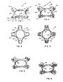
- Fig. 1 comprises a top isometric view of the clip 10 of the present invention having four discrete body portions.
- Each of the discrete body portions has hook means 20 for engaging a chime portion of the can.
- Coupled to each of the hook means 20 is a support wall means 22 having an outer wall surface 23 which is essentially concentric with the arc of the hook means 20 to provide uniform support for hook means 20.
- the discrete body portions also include ear means 12 having guiding portion means 14 and holding portion means 16. Holding portion means 16 are supported by ear shelf means 18.
- Fig. 2 is a schematic isometric bottom view of clip 10.
- Fig. 2 illustrates flange means 24 which is coupled to support wall means 22 along inner wall surface 30.
- Hinge means 26 is coupled to flange means 24 and provides a predetermined line of weakness between discrete body portions of clip 10.
- clip 10 has four discrete body portions with identical parts coupled together by hinge means 26.
- Rib support means 28 is coupled to support wall means 22 and extends beyond end portions 32 of support wall means 22 in an arcuate path, as illustrated in Fig. 2.
- Rib support means 28 is also coupled to ear shelf means 18 and limits movement of ear support means 18 during disengagement of the can.
- Fig. 3 is a schematic top view of clip 10 illustrating the circular central opening 34 which is conveniently shaped for finger engagement.
- Circular central opening 34 is disposed over the interstitial opening between a group of cans forming the multiple container package so that a users finger can be inserted in circular central opening 34 without interference from the cans held by clip 10.
- Fig. 3 also illustrates clip shelf means 36 which comprises a substantially flat upper surface of clip 10.
- Clip shelf means 36, together with ear shelf 18 comprise the upper surface of the clip 10.
- Hook means 20 has a hook point which faces in an upward direction to engage the chime portion of a can.
- Fig. 4 is a schematic bottom plan view of the clip 10. As shown in Fig. 4, flange means 24 has a substantially triangular shape and forms the surface of the circular central opening 34. Hook means 20 and support wall means 22 have a predetermined arcuate length with end portions 32 adjacent to ear means 12 and a middle portion 38 at the center of the arc. Fig. 4 also illustrates inner wall surface 30 which has a larger radius of curvature than outer wall surface 23 so that middle portibn 38 of support wall means 22 has a smaller cross-sectional thickness than end portions 32 of support wall means 22. This provides greater support at end portions 32 of hook means 20.
- Fig. 5 is a schematic bottom isometric view of an alternative embodiment utilizing flange means 24 having a structure 40 with a uniform cross-sectional thickness.
- the uniform cross-sectional thickness of flange means 24 reduces the material utilized in the clip illustrated in Fig. 5. Additional support can be provided, if necessary, by increasing the cross-sectional thickness of the support wall means 22 of the clip illustrated in Fig. 5 to provided support to the hook means 20 of the clip.
- Fig. 6 comprises an alternative embodiment having flange means 24 which are formed from a rib structure 42.
- Rib structure 42 allows removal of plastic material from central portion 44 of the flange means 24 to reduce the amount of compositional material in the clip.
- Rib structure 42 provides essentially the same structural support as the solid structure of flange means 24 in the embodiment illustrated in Figs. 1 - 4 and Fig. 5, while using substantially less compositional material.
- Clip shelf means 36 is coupled to rib structure 42 on the top surface of the clip and also provides support for rib structure 42.
- Fig. 7 is a schematic cross-sectional diagram of the chime portion 46 of a typical beverage can.
- the chime portion 46 is formed from a top portion 48 and a body wall portion 50 in a two piece can.
- Chime portions can also be formed from a body wall portion and a bottom portion in a three piece can.
- the chime portion 46 provides an air tight seal capable of withstanding pneumatic pressures generated within the can.
- Top portion 48 is formed in a configuration to produce a countersink having a predetermined countersink depth 52.
- a chime groove 54 is formed at the interface of the chime portion 46 and can body portion 50 of the can so that a seam is formed between cover hook 56 and body wall portion 50.
- the bottom of chime 46 is referred to as the cover hook radius portion 58 which has a predetermined curvature.
- the curvature of cover hook radius portion 58 is substantially uniform for most chimes formed on beverage containers.
- the cover hook radius portion 58 is coupled to seaming wall 60 which forms the outer most surface of the chime 46.
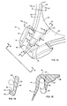
- Figs. 8 discloses the manner in which clip 10 engages chime portion 46 of the can.
- Chime portion 46 is disposed between outer wall surface 23 of support wall means 22 and the inner wall surface of holding portion means 16.
- Holding portion means 16 has sufficient spaces provided between holding portion means 16 and outer wall surface 23 to engage a wide variety of chime configurations.
- Upper portions of the couter- sink rest directly along the inner wall surface of holding portion means 16 for support.
- Hook point means 74 is disposed directly in chime groove 54 to securely engage chime portion 46.
- Hook point means 74 is disposed in the seam between a cover hook 56 and body wall portion 50.
- the shape of hook radius means 76 substantially matches the shape of cover hook radius portion 58 to provide uniform support and to securely engage chime portion 46.
- Guiding portion means 14 sits freely within the countersink of top portion 48 of the can. Sufficient flexibility is provided in guiding portion 14 to allow conformity of the guiding portion 14 to a wide variety of countersink profiles.
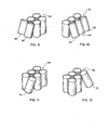
- Figs. 9 - 12 illustrate the various movement of cans in a multiple container package.
- Figs. 9 and 10 illustrate simultaneous movement of adjacent cans in directions which are substantially parallel to the multiple container package.
- Fig. 9 illustrates simultaneous parallel. movement of cans 60 and 62 from the multiple container package.
- Fig. 10 illustrates simultaneous movement of cans 64,66,68 in a direction parallel to the multiple container package.
- Figs. 11 and 12 illustrate movement of cans in a direction substantially diagonal to the multiple container package.
- Fig. 11 illustrates a substantially side diagonal movement of cans 70 relative to the multiple container package.
- Fig. 12 illustrates a substantially radial diagonal movement of can 72 relative to the multiple container package.
- Figs. 13 - 21 comprise detailed drawings of clip 10, illustrating various portions of clip 10 in detail.
- Fig. 13 comprises a detailed plan view of clip 10 illustrating the cross-sectional views of Figs. 14 - 20.
- Fig. 13 also illustrates various portions of clip 10 including ear means 12 having guiding portion means 14 holding portion means 16 and ear shelf means 18 which is coupled to holding portion means 16.
- Hook means 20 is also illustrated in Fig. 13 which is coupled to support wall means 22 having an outer wall surface 23 which is concentric with hook means 20.
- Support wall means 22 has an inner wall surface 30 which can be substantially concentric with outer wall surface 23, or a radius of curvature slightly larger than outer wall surface 23 to provide greater support to end portions which are coupled to flange means 24.
- Flange means 24 are coupled to support wall means 22 and joined by hinge means 26 which function to couple adjacent discrete body portions along a predetermined line of weakness.
- Rib support means 28 comprises an extention of structural wall 22 and are coupled to ear shelf means 18.
- Fig. 14 comprises a cross-sectional view of the support wall means 22 and hook 20.
- Support wall means has an outer wall surface 23 which is concentric with hook 20 and an inner wall surface 30 which produces a support wall which may have a constant or varying cross-sectional thickness as disclosed above.
- Hook means 20 includes hook point means 74 which engages the chime portion of 46 of the can in the chime groove 54.
- the curvature of hook means 20 is defined by hook radius means 76.
- the shape of hook radius means 76 is substantially contiguous with the shape of cover hook radius portion 58 of chime 46. In this manner, hook means 20 is capable of supporting chime 46 in a uniform manner.
- Outer wall surface 23 is substantially contiguous with seaming wall 60 to provide additional support.
- Fig. 15 is a cross-sectional view of clip 10, as illustrated in Fig. 13.
- hinge means 26 is coupled to flange means 24, which is in turn coupled to support wall means 22.
- Flange means 24 has a varying cross-sectional thickness to provide increased support to support wall means 22 at end portions 32 of hook means 20.
- Fig. 15 also illustrates the manner in which outer wall surface 23 is aligned with other portions of the clip.
- Holding portion means 16 is coupled to ear shelf means 18 and functions to maintain engagement of chime 46 with hook means 20.
- Guiding portion means 14 is coupled to holding portion means 16 and functions to guide the clip 10 into engagement with the can.
- Guiding portion means 14 is flared to have a decreasing cross-sectional thickness so as to provide sufficient flexibility to allow guiding portion means 14 to conform to a wide range of countersink depths 52.
- Figs. 16 and l7 comprise cross-sectional views of ear means 12.
- Fig. 16 illustrates guiding portion means 14 and holding portion means l6 of ear means 12 which are coupled to rib support structure 28.
- Flange 24 is coupled to rib support structure 28 and provides support to rib support structure 28 for a substantial portion of the length of ear means 22.
- the curved inclined portion of hinge means 26 is also illustrated in Fig. 16, which forms a line of weakness along the decreased cross-sectional thickness of ear shelf means 18, as illustrated in Fig. 16.
- Fig. 17 illustrates a cross-sectional view of ear means 12 including portions of support wall means 22 and hook means 20. As is shown in Fig. 17, rib support means 28 is coupled to the end portions of hook means 20 and support wall means 22.
- the cross-sectional thickness of ear shelf means 18 along hinge means 26, as illustrated in Fig. 17, provides sufficient flexibility to allow the discrete body portions of the clip to flex along the lines of weakness of hinge means 26.
- Fig. 18 is an end view of ear means 12. Guiding portion means 14 and holding portion means 16 are curved to fit the arcuate path of the chime 46 of the can. Rib support means 28 is curved along the same arcuate path formed in ear groove 90. Fig. 18 also illustrates the manner in which hinge means 26 decreases the cross-sectional thickness of ear shelf means 18 to provide flexibility between discrete body portions.
- Figs. 19 and 20 comprise cross-sectional views of portions of ear means 12.
- Figs. 19 and 20 illustrate the manner in which the width of flange means 24 gradually decreases in a direction toward the end of ear means 12.
- Figs. 19 and 20 also illustrate the reduced cross-sectional thickness of hinge means 26 in comparison to ear shelf means 18.
- Fig.-21 is a cross-sectional view illustrating an alternative embodiment of ear means 12.
- hook means 20, support wall means 22, flange means 24 and ear shelf means 18 are identical to the corresponding parts illustrated in Fig. 15.
- Notches 78 and 80 are provided between guiding portion means 14 and holding portion means 16 in the embodiment of Fig. 21 to provide flexibility to guiding portion means 14 such that ear means 12 is capable of conforming to a wide range of countersink depths.
- Notches 78 and 80 reduce the 1 0coss-sectional thickness at the interface of guiding portion 14 and holding portion 16 to allow guiding portion 14 to flex relative to holding portion 16 to allow the guiding portion 14 to conform to the countersink of the can during engagement.
- Notches 78 and 80 are located below the adjacent portion of hook means 20 so that the holding ability of holding portion 16 is not reduced.
- clip 10 In operation, clip 10, as illustrated in Figs. 1 - 6 and 13 - 21, has four discrete body portions, each of which is capable of holding a can to form a multiple container package.
- Hook means 20 engages the chime portion of the can along a predetermined arcuate length of the chime portion.
- the hook means has a hook point 74 which is disposed in the chime groove 54 of the can at the interface between the body wall portion 50 and cover hook portion 56 to: securely hold the hook means 20 in interlocking engagement with the chime portion 46.
- the hook point means 74 substantially fills the chime groove 54 and is disposed in the seam of the chime groove 54 to increase the holding ability of the hook means 20.
- Hook means 20 has a hook radius 76 with a curved shape which is contiguous with the curved shape of the cover hook radius portion 58 of chime portion 46. This further increases the holding ability of hook means 20 since the clip more securely engages the chime portion 46 of the can.
- Support wall means 22 is coupled to the hook means 20 and has a shape which is concentric with the arcuate shape of the hook means 20 so as to provide uniform support to the hook means along the entire arcuate length which the hook means 20 engages the chime portion 46 of the can.
- the outer wall surface 23 of support wall means 22 comprises a substantially vertical support structure which is concentric with the arcuate path of hook means 20 so as to provide support to end portions 32 of hook means 20 which is essentially equal to the support provided to middle portion 38 of hook means 20.
- the uniform support provided by support wall 22 prevents progressive disengagement of the clip, especially in response to side diagonal movement such as illustrated by the movement of can 70 in Fig. 11.
- Side diagonal movement of the cans in the multiple container package 59 produces increased torque on end portions 32 of hook means 20.
- Support is also provided to ear means 12 by rib support means 28 which follows the arcuate path of support wall means 22 and extends into ear means 12 to support ear shelf means 18 in response to side diagonal movement, such as illustrated in Fig. 11.
- the support wall means 22 can, alternatively have an inner wall surface 30 with a larger radius of curvature, as illustrated in Fig. 4, to provide added support to end portions 32 of support wall means 22.
- Flange means 24 also provides additional support to end portions 32 of support wall means 22, as well as ear shelf means 18. However, flange means 24 has a structure which is aligned with hinge means 26 so that flange means 24 is capable of substantially maintaining the position of support wall means 22 relative to the remaining portions of the clip in response to radial diagonal movement, such as illustrated by can 72 in Fig. 12.
- flange means 24 limits the movement of support wall means 22 and ear shelf means 18 relative to the clip by an amount sufficient to maintain engagement of the hook means 20 and the chime portion 46 of the can in response to forces produced by the cans on the clip 10 during normal handling, while simultaneously allowing holding portion means 16 and guiding portion means 14 of ear means 12 to bend outwardly in response to radial diagonal movement of the can, so as to allow disengagement of the hook means 20 from the chime portion 46 of the can.
- the holding ability of clip 10 is greatly increased by the shape of hook means 20 as well as the uniform support provided by support wall means 22 and rib support means 28, so as to prevent accidental disengagement in response to normal handling movements, such as side diagonal movements, while allowing easy disengagement of the can from clip 10 in response to radial diagonal movement, by limiting movement of the support wall means 22 and ear shelf means 18 relative to other discrete body portions of the clip.
- hinge means 26 which provides a line of weakness allowing simultaneous bending of adjacent discrete body portions of clip 10 joined by hinge means 26.
- the flexible web portion of hinge means 26 allows simultaneous movement of adjacent cans in directions substantially parallel to the multiple container package, such as illustrated in Figs. 9 and 10. This discreases torque on the hook means 20 for movement of cans in directions parallel to the multiple container package 59.
- Figs. 22 and 23 illustrate covers which can be used in conjunction with clip 10, as illustrated in Figs. 1 through 6 and 13 through 21.
- Cover means 82 illustrated in Fig. 22, has a main body portion 83 and side panel portions 84 which maintain the relative position of cover means 82 with respect to the multiple container package 59.
- Cover means 82 has tabs formed in main body portion 83 which engage clip 10 to hold cover means 82 in engagement with clip 10. Tab portions formed in main body portion 83 are inserted thraugh circular central opening 34.
- Cover means 82 covers chime portion 46 of the cans forming the multiple container package 59 and provide protection to the top surfaces of the cans from contaminates.
- Coupon means 88 can be formed from main body portion 83 and detached therefrom by cut and score lines, as illustrated in Fig. 22, or can comprise separate coupon means 88 attached to main body portion 83 for removal from cover means 82.
- Fig. 23 illustrates an additional cover means 86 which covers only a portion of the tops of the cans in the multiple container package 59.
- Cover 86 is attached to clips 10 in the same manner as disclosed in the above- identified application.
- Cover 86 can, itself, comprise a coupon or have a portion thereof formed as a coupon for removal from cover 86, as illustrated in Fig. 23, or have a coupon attabbed thereto.
- the present invention provides a clip for forming a multiple container package which has increased holding ability and provides uniform support to prevent accidental disengagement of cans from the multiple container package, while allowing easy disengagement of individual cans from the multiple container package by radial diagonal movement.
- the clip provides sufficient torque stability as a result of the uniform support provided by a concentric support wall to prevent accidental disengagement in response to side diagonal movement, while simultaneously providing increased holding ability.
- Flange means are also provided which limit movement of discrete body portions during disengagement to allow the holding portion of the ear means to move relative to the hook means so that the container can be disengaged from the clip without substantial difficulty. Consequently, cans are held in the multiple container package with great stability to maintain engagement of the cans with the clip in the multiple container package in response to normal handling movements and allow disengagement from the clip with relative ease by radial diagonal movement.
- the clip of the present invention is normally formed by conventional injection molding techniques using thermo-plastic materials such as acrylonitrile-butadiene-styrene, polyesters such as polyethylene terephthalate, or polypropylene, polystyrene, or other suitable materials or methods of forming the clip can be used.
Landscapes
- Engineering & Computer Science (AREA)
- Mechanical Engineering (AREA)
- Packages (AREA)
Applications Claiming Priority (2)
| Application Number | Priority Date | Filing Date | Title |
|---|---|---|---|
| US06/524,129 US4552265A (en) | 1983-08-17 | 1983-08-17 | Can clip and multiple container package |
| US524129 | 1990-05-14 |
Publications (2)
| Publication Number | Publication Date |
|---|---|
| EP0134148A2 true EP0134148A2 (fr) | 1985-03-13 |
| EP0134148A3 EP0134148A3 (fr) | 1986-05-28 |
Family
ID=24087881
Family Applications (1)
| Application Number | Title | Priority Date | Filing Date |
|---|---|---|---|
| EP84305603A Withdrawn EP0134148A3 (fr) | 1983-08-17 | 1984-08-17 | Agrafe pour relier des boítes et emballage comportant plusieurs boítes |
Country Status (5)
| Country | Link |
|---|---|
| US (1) | US4552265A (fr) |
| EP (1) | EP0134148A3 (fr) |
| JP (1) | JPS6068264A (fr) |
| AU (1) | AU3193784A (fr) |
| ZA (1) | ZA846311B (fr) |
Families Citing this family (6)
| Publication number | Priority date | Publication date | Assignee | Title |
|---|---|---|---|---|
| GB2223314A (en) * | 1988-09-20 | 1990-04-04 | Jinks Alan Peter | Buffering device |
| GB2277506B (en) * | 1993-04-30 | 1996-08-21 | Alloy Wheels Int Ltd | Locking spacer for protecting wheels during transport |
| USD406526S (en) * | 1998-03-30 | 1999-03-09 | Headrick Joseph R | Detachable holder for drink cans |
| WO2011101519A1 (fr) * | 2010-02-18 | 2011-08-25 | Cana Martinez Francisco Javier | Dispositif de fixation pour récipients extractibles |
| USD744832S1 (en) * | 2014-01-17 | 2015-12-08 | Karl Fredrick Biewald | Holder for stacked beverage cans |
| US9669976B2 (en) | 2014-04-11 | 2017-06-06 | Graphic Packaging International, Inc. | Container clip for engaging at least one container |
Family Cites Families (11)
| Publication number | Priority date | Publication date | Assignee | Title |
|---|---|---|---|---|
| US3126599A (en) * | 1964-03-31 | Figure | ||
| US911884A (en) * | 1905-06-13 | 1909-02-09 | John A Kyle | Coupon or tag for cartons. |
| US2810171A (en) * | 1953-03-03 | 1957-10-22 | Norberg | Can holder |
| US2815855A (en) * | 1954-02-24 | 1957-12-10 | Larry Crosby | Container carrier clip |
| US3002612A (en) * | 1956-11-06 | 1961-10-03 | Illinois Tool Works | Can carrier |
| US3331500A (en) * | 1959-07-17 | 1967-07-18 | Illinois Tool Works | Container carrier and package |
| US3357551A (en) * | 1962-02-12 | 1967-12-12 | Combi Clip Co | Package of cans and a clip for interconnecting cans |
| US3321076A (en) * | 1963-12-23 | 1967-05-23 | Illinois Tool Works | Container carrier |
| US3410398A (en) * | 1967-07-17 | 1968-11-12 | Fed Paper Board Co Inc | Clip and wraparound package combination |
| US4216859A (en) * | 1979-01-22 | 1980-08-12 | Adolph Coors Company | Can clip and package |
| US4423810A (en) * | 1981-08-14 | 1984-01-03 | Adolph Coors Company | Cover for multiple unit container packages |
-
1983
- 1983-08-17 US US06/524,129 patent/US4552265A/en not_active Expired - Fee Related
-
1984
- 1984-08-14 ZA ZA846311A patent/ZA846311B/xx unknown
- 1984-08-15 AU AU31937/84A patent/AU3193784A/en not_active Abandoned
- 1984-08-17 JP JP59171413A patent/JPS6068264A/ja active Pending
- 1984-08-17 EP EP84305603A patent/EP0134148A3/fr not_active Withdrawn
Also Published As
| Publication number | Publication date |
|---|---|
| US4552265A (en) | 1985-11-12 |
| JPS6068264A (ja) | 1985-04-18 |
| EP0134148A3 (fr) | 1986-05-28 |
| AU3193784A (en) | 1985-02-21 |
| ZA846311B (en) | 1985-03-27 |
Similar Documents
| Publication | Publication Date | Title |
|---|---|---|
| US4139094A (en) | Carrier for bottles | |
| US4712680A (en) | Reinforced self-centering plastic carrier for bottles | |
| US5443153A (en) | Clip-type article carrier | |
| US5592766A (en) | Container lid/closure with printed closure insert | |
| US6056144A (en) | Beverage cup with locking lid | |
| RU2266247C2 (ru) | Верхний захватный держатель бутылок | |
| US3331500A (en) | Container carrier and package | |
| US5415278A (en) | Clip-type can carrier | |
| US5964343A (en) | Carrying plate for beverage cans | |
| US5520301A (en) | Plastic packaging | |
| US5305877A (en) | Carrier stock with outer band segments having concave edge portions | |
| GB2065061A (en) | Reclosable containers | |
| JPH03133751A (ja) | 缶の蓋を固定する装置 | |
| US4385690A (en) | Package unit carrier | |
| EP1113965A1 (fr) | Accessoire pour goulot de bouteille | |
| JPS60134865A (ja) | びんの一括包装体と、一括包装装置 | |
| US3370700A (en) | Clip for interconnecting cans to form a multiple can package | |
| US4552265A (en) | Can clip and multiple container package | |
| EP0013838B1 (fr) | Porte-boîtes | |
| US3348674A (en) | Container carrier and package | |
| US3527377A (en) | Protective member for sharp-edge dispensing openings | |
| US4457426A (en) | Multiple bottle assembly | |
| US3814274A (en) | Linerless closure for a container | |
| US3263724A (en) | Container cap finish and cap | |
| US4848565A (en) | Carrier devices and packages of containers |
Legal Events
| Date | Code | Title | Description |
|---|---|---|---|
| PUAI | Public reference made under article 153(3) epc to a published international application that has entered the european phase |
Free format text: ORIGINAL CODE: 0009012 |
|
| AK | Designated contracting states |
Designated state(s): AT BE CH DE FR GB IT LI LU NL SE |
|
| PUAL | Search report despatched |
Free format text: ORIGINAL CODE: 0009013 |
|
| AK | Designated contracting states |
Kind code of ref document: A3 Designated state(s): AT BE CH DE FR GB IT LI LU NL SE |
|
| STAA | Information on the status of an ep patent application or granted ep patent |
Free format text: STATUS: THE APPLICATION IS DEEMED TO BE WITHDRAWN |
|
| 18D | Application deemed to be withdrawn |
Effective date: 19870310 |
|
| RIN1 | Information on inventor provided before grant (corrected) |
Inventor name: BADER, JAMES S. |