EP0134286A2 - Procédé et appareil pour séparer un mélange huile-eau - Google Patents
Procédé et appareil pour séparer un mélange huile-eau Download PDFInfo
- Publication number
- EP0134286A2 EP0134286A2 EP83108657A EP83108657A EP0134286A2 EP 0134286 A2 EP0134286 A2 EP 0134286A2 EP 83108657 A EP83108657 A EP 83108657A EP 83108657 A EP83108657 A EP 83108657A EP 0134286 A2 EP0134286 A2 EP 0134286A2
- Authority
- EP
- European Patent Office
- Prior art keywords
- oil
- water
- container
- suction
- mixture
- Prior art date
- Legal status (The legal status is an assumption and is not a legal conclusion. Google has not performed a legal analysis and makes no representation as to the accuracy of the status listed.)
- Granted
Links
- 235000019476 oil-water mixture Nutrition 0.000 title claims abstract description 29
- 238000000034 method Methods 0.000 title claims abstract description 18
- 235000019198 oils Nutrition 0.000 claims abstract description 146
- XLYOFNOQVPJJNP-UHFFFAOYSA-N water Substances O XLYOFNOQVPJJNP-UHFFFAOYSA-N 0.000 claims abstract description 118
- 239000007788 liquid Substances 0.000 claims abstract description 95
- 238000000926 separation method Methods 0.000 claims abstract description 26
- 239000000203 mixture Substances 0.000 claims abstract description 22
- 230000000977 initiatory effect Effects 0.000 claims abstract description 3
- 238000005192 partition Methods 0.000 claims description 9
- 230000005484 gravity Effects 0.000 claims description 6
- 238000000605 extraction Methods 0.000 description 3
- 238000012423 maintenance Methods 0.000 description 2
- 239000003643 water by type Substances 0.000 description 2
- 238000010521 absorption reaction Methods 0.000 description 1
- 230000006978 adaptation Effects 0.000 description 1
- 230000000694 effects Effects 0.000 description 1
- 230000007613 environmental effect Effects 0.000 description 1
- 230000002349 favourable effect Effects 0.000 description 1
- 230000001771 impaired effect Effects 0.000 description 1
- 239000003999 initiator Substances 0.000 description 1
- 239000000463 material Substances 0.000 description 1
- 239000007769 metal material Substances 0.000 description 1
- 229920003023 plastic Polymers 0.000 description 1
- 239000004033 plastic Substances 0.000 description 1
- 230000000630 rising effect Effects 0.000 description 1
- 239000004551 spreading oil Substances 0.000 description 1
- 238000003809 water extraction Methods 0.000 description 1
Images

Classifications
-
- E—FIXED CONSTRUCTIONS
- E02—HYDRAULIC ENGINEERING; FOUNDATIONS; SOIL SHIFTING
- E02B—HYDRAULIC ENGINEERING
- E02B15/00—Cleaning or keeping clear the surface of open water; Apparatus therefor
- E02B15/04—Devices for cleaning or keeping clear the surface of open water from oil or like floating materials by separating or removing these materials
- E02B15/045—Separating means for recovering oil floating on a surface of open water
-
- B—PERFORMING OPERATIONS; TRANSPORTING
- B01—PHYSICAL OR CHEMICAL PROCESSES OR APPARATUS IN GENERAL
- B01D—SEPARATION
- B01D17/00—Separation of liquids, not provided for elsewhere, e.g. by thermal diffusion
- B01D17/02—Separation of non-miscible liquids
- B01D17/0208—Separation of non-miscible liquids by sedimentation
- B01D17/0211—Separation of non-miscible liquids by sedimentation with baffles
-
- B—PERFORMING OPERATIONS; TRANSPORTING
- B01—PHYSICAL OR CHEMICAL PROCESSES OR APPARATUS IN GENERAL
- B01D—SEPARATION
- B01D17/00—Separation of liquids, not provided for elsewhere, e.g. by thermal diffusion
- B01D17/02—Separation of non-miscible liquids
- B01D17/0208—Separation of non-miscible liquids by sedimentation
- B01D17/0214—Separation of non-miscible liquids by sedimentation with removal of one of the phases
-
- Y—GENERAL TAGGING OF NEW TECHNOLOGICAL DEVELOPMENTS; GENERAL TAGGING OF CROSS-SECTIONAL TECHNOLOGIES SPANNING OVER SEVERAL SECTIONS OF THE IPC; TECHNICAL SUBJECTS COVERED BY FORMER USPC CROSS-REFERENCE ART COLLECTIONS [XRACs] AND DIGESTS
- Y02—TECHNOLOGIES OR APPLICATIONS FOR MITIGATION OR ADAPTATION AGAINST CLIMATE CHANGE
- Y02A—TECHNOLOGIES FOR ADAPTATION TO CLIMATE CHANGE
- Y02A20/00—Water conservation; Efficient water supply; Efficient water use
- Y02A20/20—Controlling water pollution; Waste water treatment
- Y02A20/204—Keeping clear the surface of open water from oil spills
Definitions
- the invention relates to a method for separating a mixture of water and oil which is supplied to a closed space and fluctuates in quantity and mixing ratio and has a lower specific weight than water, and a device designed to carry out the method.
- the invention solves the problem of creating a method and a device with which it is possible to economically separate an oil-water mixture, regardless of whether it is the oil-water mixture from an open sea, oil layer floating in the water of a harbor basin or on the water of a river or lake.
- Another object of the invention is to design the separation device in such a way that it is portable and can be used both at sea and on land and also from an aircraft such as a helicopter.
- the invention provides a method for separating a mixture of water and oil, which is supplied to a closed room and fluctuates in quantity and mixing ratio and has a specific gravity that is lower than that of water, according to the invention from the upper region of the closed, the oil-water Mixture-receiving space, the oil of the oil layer collecting on the water, depending on the respective level of the liquid level of the mixture in the room and its lower region, water is sucked off separately, the oil suction being interrupted and resumed when a thin oil layer is reached, when the oil layer has reached a predetermined thickness for initiating the suction process.
- Another method according to the invention is that from the upper area of the closed, the oil-water mixture receiving space, the oil of the oil layer collecting on the water depending on the respective level of the liquid level of the mixture in the room and from the bottom thereof Area water are sucked separately from each other, and that by measuring the changing level of the liquid level of the mixture, the oil suction and the water suction are controlled in such a way that the suction process is interrupted for which the amount of oil or the amount of water to the separating plane oil / Water falls below a minimum value.
- the invention further provides a device for separating a mixture of water and oil having a specific gravity that is lower than that of the water and which is supplied to a container and fluctuates in quantity and mixing ratio, and which is designed according to the invention in such a way that in which a Supply line for the oil-water mixture provided container in the upper area of a floating on the liquid level and the respective height of the liquid level-adjusting float with an oil suction port and a to these subsequent flexible with the container firmly connected oil suction line with a suction pump and in the lower region of the fixed Wasseransaug - opening an Wasserabsaugtechnisch provided with a suction pump, fixed to the container and in the height range of movement of the float with the oil suction opening there are arranged a control signal transmitter or liquid level measuring device which defines the respective upper and lower oil suction limit and in the area of the water suction opening there is another control signal transmitter or liquid level measuring device which defines the respective upper and lower water suction limit, and that the two control signal transmitters or liquid level measuring devices are
- the separation device By means of the separation device, this is done without complex technical equipment Separation of oil and water, in such a way that from the upper part of the container, the oil and from its lower part, the water are sucked out through a line, the oil suction line inside the container on the articulated and height-adjustable with the container connected float attached and elastic, while the water suction line is firmly connected to the container.
- the two suction pumps of the oil suction line and the water suction line are controlled so that the pump is switched off at which the distance of its suction opening in the container to the oil / water separation level falls below a minimum value.
- the container with the separation device can also be mounted on the chassis of a vehicle and can therefore be used as a mobile emergency vehicle wherever oil is to be extracted and separated from the water. Furthermore, there is the possibility of arranging the container with the separating device in the interior of a ship, so that the oil can be taken up by a spread oil slick and separated from the water even on the high seas.
- the separation device with the float having the oil suction opening is arranged in the interior of a container, it is possible to create floating oil layers on the water with a large thickness, so that large amounts of oil can be separated from water and drained. Since the float adapts to the respective height of the liquid level in the interior of the container, optimal separation and absorption of oil is guaranteed. If the oil layer floating on the water in the interior of the container has only a small thickness, then the oil extraction is interrupted and only water is still extracted, so that the entire liquid level in the interior of the container is lowered.
- the embodiment according to the invention according to claim 8 is particularly advantageous, according to which the container is provided with a receptacle which can be closed by means of a removable cover part on which the holder for the float, the two suction lines, the suction pumps, the control device and the connections for the oil drainage and are attached for water drainage.
- This configuration enables the separating device to be exchanged quickly and easily with the float, should this be necessary, for example, for maintenance or the like.
- this configuration has the advantage that only empty containers have to be set up locally in the area of danger points, which are then equipped with the separating device arranged on the cover for the receptacle of the container, in that only the lid with the separating device is placed on the receptacle and with screwed to it.
- the feed line for the oil-water mixture is provided with a hose line, so that the p arian se to oil-water mixture to the container can be supplied.
- the connecting pieces provided on the cover for the oil drainage and water drainage are to be provided with hose lines in a corresponding manner, so that the oil and water can be pumped into appropriately prepared storage containers after separation.
- Both the rising oil bubbles as well as the descending thick water bubbles are looking for the shortest route to the intake manifold in the tank.
- the shortest route is the route through the slot-shaped openings in the upper and lower end regions of the liquid flow guide walls. This achieves a high flow rate and rapid drainage of the oil and water separated from the oil-water mixture.
- the mixture of oil-water bubbles takes a longer time to separate. However, since the separated thick oil bubbles and the thick water bubbles are immediately drained off, this rapid draining cannot be impaired by the mixture of oil-water bubbles. While the thick oil bubbles and the thick water bubbles are being drained, the mixture of oil and water bubbles can be separated, which takes more time because they have to flow through the labyrinth formed by the liquid flow guide walls .
- the invention further provides an apparatus for separating a mixture of water and oil having a specific gravity that is lower than that of water and which is supplied to a container and fluctuates in quantity and mixture ratio, and is designed in such a way that the closed container is formed by means of a vertical partition wall is divided into two chambers, the bottom of which is provided with openings, that the antechamber is provided with an oil-water mixture feed line and in its interior has a control signal transmitter or liquid level measuring device which extends over the entire chamber height and is connected to the outside air via an opening that the suction openings of an oil suction line and a water suction line are arranged in the interior of the airtightly sealed chamber, that both suction lines have suction pumps which are connected to a control device that the oil suction opening of the oil suction line in the upper region the container chamber and the suction opening of the water suction line are arranged in the bottom region of the container chamber, and that a control signal transmitter or liquid level measuring device is arranged in the area of each suction opening, the two control signal
- a device designed in this way has the simplest components and is easy to handle.
- the oil floating on the water in the interior of this container is sucked off, control of the suction pumps being carried out in the same way in that the suction pump is switched off in which the distance of the suction opening of its suction line to the oil / water separation level falls below a minimum value.
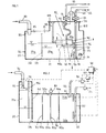
- the device for separating an oil-water mixture consists of a closed container 20 with the bottom 21, the side walls 22, 23, 24, 25 and the top cover 26.
- a feed line 30 is provided, which is connected to the upper cover 26 of the container 20. This connection can also be made by means of a connecting piece 33 (Fig. 2).
- a float 40 which floats on the liquid level FS in the interior of the container and is connected to the upper cover 26 of the container 20 via a holder 49.
- the design of this holder 49 and the connection of the float 40 to this holder is such that the float 40 can freely follow the respective height of the liquid level FS.
- the oil-water mixture supplied via the feed line 30 is located in the interior 27 of the container 20.
- the oil layer is labeled “oil” and the water layer is labeled “water”.
- the float 40 can also be guided and held by means of guides in the interior 27 of the container 20. These guides, indicated at 49a, are provided on the opposite side walls of the container 20. The float 40 is then guided in these two guides 49a.
- the guides 49a are designed in the form of a circular arc, so that the float 40 is properly guided in adaptation to the respective oil level of the liquid level.
- the float 40 which consists of a suitably designed hollow body made of metallic materials, plastics or other suitable materials, has an oil suction opening 41 on its wall surface 40a facing the bottom 21 of the container 20, which is connected to a flexible oil suction line 42, which is connected to a Port 43 is connected in the top cover 26 of the container 20. Outside the container 20, an oil drain 45 is connected to this connecting piece 43, into which a suction pump 44 is switched on, via which the oil of the oil layer of the liquid in the interior 27 of the container 20 is sucked in and supplied via the oil drain 45 to a reservoir, not shown in the drawing becomes.
- the oil suction line 42 is designed as a flexible hose, the oil suction line 42 adapts to any height position of the float 40 in the interior 27 of the container 20.
- a control signal transmitter or liquid level measuring device 46 is arranged in the height movement range of the float 40.
- This control signal generator or liquid level measuring device 46 is fixedly arranged in the interior 27 of the container 20 and controls the operation of the suction pump 44 in the oil suction line 42 or in the oil drain 45 via a control device 60.
- the suction pump 44 is in the connecting piece 43 in the upper cover 26 of the Container 20 arranged.
- the flexible oil suction line 42 receives the necessary electrical lines via which the control pulses for the motor of the suction pump 44 are conducted when the control signal transmitter or the liquid level measuring device 46 operate by means of contact sensors.
- a purely mechanical configuration is also possible. On the operation of the control signal transmitter or rivers liquid level measuring device 46 will be discussed in more detail below.
- the oil suction opening 41 in the float 40 is covered by a plate 48 arranged at a distance from the oil suction opening 41 on the bottom wall surface 40a of the float 40, so that the oil can only flow in radially and in the horizontal direction (FIG. 1).
- a water suction line 52 is also arranged in the interior 27 of the container 20, the water suction opening 51 of which comes to rest in the bottom-side region 20b of the interior 27 of the container 20.
- This water suction line 52 is designed as a rigid pipe and is firmly connected to the upper cover 26 of the container 20.
- the water suction line 52 can be connected to the upper cover 26 of the container 20 by means of a connecting piece 53 which is fastened to the upper cover 26 and to which a water drainage 55 lying outside the container 20 can be connected.
- a suction pump 54 is arranged in the water suction line 52 or in the connecting piece 53 or in the water discharge line 55.
- a control signal transmitter or liquid level measuring device 56 is arranged in the area of the water suction opening 51, which assumes a fixed position in the interior 27 of the container 20. The operation of this control signal transmitter or liquid level measuring device 56 corresponds to that of the control signal transmitter or liquid level measuring device 46.
- An electrical line can also be arranged in the water suction line 52 starting from the control signal transmitter or liquid level measuring device 56 if electrical control devices are provided.
- the respective upper and lower Oil extraction limit and the respective upper and lower water extraction limit By means of the two control signal transmitters and liquid level measuring device 46, 56, the respective upper and lower Oil extraction limit and the respective upper and lower water extraction limit.
- the two control signal transmitters or liquid level measuring devices 46, 56 are brought together in the control device 60, which can be controlled via the two suction pumps 44, 54 in the two suction lines 42, 52 such that the suction pump is switched off, in which the distance between the suction opening and the oil separation plane / Water falls below a minimum value.
- Both control signal transmitters or liquid level measuring devices 46, 56 have end limits A and B or C and D.
- the oil suction pump 44 sucks as long as the measured value is greater than AB.
- the water suction pump 54 is also in operation as long as the measured value is greater than CD.
- the two suction pumps 44, 54 are controlled so that the pump is switched off at which the distance of its suction opening in the container to the oil / water separation level falls below a minimum value.
- the two control signal transmitters or liquid level measuring devices 46, 56 are designed in a manner known per se; they can also be designed as liquid proximity initiators.
- the container interior 27 is divided into two chambers 27a, 27b by means of a partition wall 28.
- the partition wall 28 is designed so that it has at least one opening or a plurality of openings 29 on the bottom side, so that the oil-water mixture introduced into the chamber 27a can enter the chamber 27b, so that the oil layer forming on the water surface forms on the partition wall 28 can collect ( Fi g. L ).
- the overall control of the suction pumps 44, 54 in connection with the inlet for the oil-water mixture via the feed line 30 is such that the thickest possible oil layer is formed in the container interior 27 and that this oil layer is kept in the area of the float 40 if possible, however, due to the arrangement of the float 40 in the container interior 27 of the float height changes stations of the liquid level can easily follow, so that the float 40 is always in the oil layer.
- the container 20 is provided in its upper region 20a with a receptacle 128 for the float 40, the flexible oil suction line 42 and the water suction line 52. Because of the dome formed in this way, it is possible to allow the liquid level in the container interior 27 to rise relatively high, but not to the interior of the receptacle 128, which then serves to accommodate the flexible oil suction line 42 and the float 40.
- the receptacle 128 can be closed by means of a removable cover 129, to which the holder 49 for the float 40, the two suction lines 42 and 52, the suction pumps 44, 54, the control device 60 and the connections for the oil drain 45 and the water drain 55 are fastened .
- the float 40, its oil suction opening 41, the flexible oil suction line 42 connected to it, the suction socket 53 and the suction pump 44 form the oil suction device 10 which, due to the design of the receiving socket 128, is fastened to it with a removable cover 129 and can be effortlessly removed from the interior of the container for maintenance 27 can be removed.
- the water suction line 52 with the suction pump 54 and the connecting piece 53 are also attached to the cover 129 of the receiving piece 128 (FIG. 1).
- the interior 27 of the container 20 is divided by a partition 28 with a bottom opening 29 into two chambers 27a, 27b which are connected to one another via this opening 29, of which the chamber 27b forms the main chamber in which the oil suction device or separation device 10 is arranged, while the chamber 27a is connected as a pre-chamber with the supply line 30 for the supply of the oil-water mixture.
- a liquid level measuring device 156 is arranged in the pre-chamber 27a.
- the chamber 27a is also connected to the outside air via an opening 34.
- the chamber 27b of the container 20, which is separated from the chamber 27a by the partition 28 with the bottom opening 29, is designed to be closed on all sides, except for the connection opening 29 to the chamber 27a.
- the chamber 27b is provided with an air extraction device 87. Furthermore, the oil suction line 42 with the oil suction opening 41 and the water suction line 52 with the water suction opening 51 are arranged in the chamber 27b. In this embodiment shown in FIG. 2, however, the oil suction line 42 need not be designed as a flexible line.
- the suction pump 44 is arranged in the oil suction line 42 and the suction pump 54 is arranged in the water suction line 52. On the pressure port side, the oil drain 45 and the water drain 55 are connected to both suction pumps 44, 54.
- the arrangement of the oil suction line and the water suction line in the chamber 27b is such that the oil suction opening 41 of the oil suction line 42 is arranged in the upper region 20a of the chamber 27b, while the water suction opening 51 of the water suction line 52 lies in the bottom region of the chamber 27b.
- a control signal transmitter or liquid level measuring device 46, 56 is arranged in the area of both suction openings 41, 51.
- the control signal transmitters or liquid level measuring devices 46, 56 are combined in the control device 60.
- liquid flow guide walls 70 are arranged, the length of which is shorter than the width of the container 20 and of which every second liquid flow guide wall is fastened to one of the two side walls 24, 25 of the container 20, while the other liquid flow guide walls 70 are attached to the opposite side wall of the container 20 are connected.
- two liquid flow guide walls are arranged on the container side wall 24 following the partition 28 in the chamber 27b of the container 20, while a single liquid flow guide wall 70 is fastened to the opposite container side wall 25, which wall wall is between the two on the container side wall 26 attached liquid flow guide walls.
- All liquid flow guide walls are dimensioned shorter than the width of the container 20 so that the liquid can flow through between the liquid flow guide walls.
- the free ends of the liquid flow guide walls 70 are provided with liquid deflection profiles 71, so that a favorable flow of the liquid through the chamber 27b is ensured.
- the liquid flow guide walls 70 arranged in the chamber 27b of the container 20 have a height which is lower than the height of the container 20, so that in the two end regions of each liquid flow guide wall 70 adjacent to the upper and lower container walls, slit-shaped openings 70a are formed.
- the container 20 with the oil suction device 10 and the water suction line 52 is designed as an attachment to the chassis of motor vehicles or railway vehicles. It is also possible to install the container 20 in ship rooms.
- the liquid level measuring device 156 arranged in the prechamber 27a of the container interior 27 and the control signal transmitter or liquid level measuring devices 46, 56 arranged in the main chamber 27b are connected to a pump motor speed control device 90 (FIG. 2).
- the pump motor speed control device 90 records the measured values of the measuring devices 46, 56, 156 as actual values and compares these measured values with predetermined target values to control the motors of the suction pumps 44, 54.
Landscapes
- Chemical & Material Sciences (AREA)
- Engineering & Computer Science (AREA)
- Physics & Mathematics (AREA)
- Thermal Sciences (AREA)
- Chemical Kinetics & Catalysis (AREA)
- General Engineering & Computer Science (AREA)
- Oil, Petroleum & Natural Gas (AREA)
- Environmental & Geological Engineering (AREA)
- Mechanical Engineering (AREA)
- Civil Engineering (AREA)
- Structural Engineering (AREA)
- Removal Of Floating Material (AREA)
Priority Applications (3)
| Application Number | Priority Date | Filing Date | Title |
|---|---|---|---|
| AT83108657T ATE45336T1 (de) | 1983-08-27 | 1983-09-02 | Verfahren zum separieren eines oel-wassergemisches und hierfuer ausgebildete vorrichtung. |
| NO83834037A NO160610C (no) | 1983-08-27 | 1983-11-04 | Innretning for separering av en til en beholder tilfoert olje/vannblanding. |
| NO88884251A NO167125C (no) | 1983-08-27 | 1988-09-26 | Innretning for separering av en til en beholder tilfoert olje/vannblanding. |
Applications Claiming Priority (2)
| Application Number | Priority Date | Filing Date | Title |
|---|---|---|---|
| DE19838324679U DE8324679U1 (de) | 1983-08-27 | 1983-08-27 | Vorrichtung zum separieren eines oel-wasser-gemisches |
| DE8324679U | 1983-08-27 |
Publications (3)
| Publication Number | Publication Date |
|---|---|
| EP0134286A2 true EP0134286A2 (fr) | 1985-03-20 |
| EP0134286A3 EP0134286A3 (en) | 1986-09-10 |
| EP0134286B1 EP0134286B1 (fr) | 1989-08-09 |
Family
ID=6756554
Family Applications (1)
| Application Number | Title | Priority Date | Filing Date |
|---|---|---|---|
| EP83108657A Expired EP0134286B1 (fr) | 1983-08-27 | 1983-09-02 | Procédé et appareil pour séparer un mélange huile-eau |
Country Status (2)
| Country | Link |
|---|---|
| EP (1) | EP0134286B1 (fr) |
| DE (2) | DE8324679U1 (fr) |
Cited By (17)
| Publication number | Priority date | Publication date | Assignee | Title |
|---|---|---|---|---|
| EP0206915A3 (en) * | 1985-06-14 | 1988-05-11 | Lucien Chastan-Bagnis | Cleaning apparatus for water surfaces |
| DE3909372A1 (de) * | 1989-03-22 | 1990-09-27 | Preussag Ag | Verfahren und vorrichtung zum entfernen einer auf einer grundwasseroberflaeche schwimmenden, fluessigen phase |
| DE4421026A1 (de) * | 1994-06-16 | 1994-11-03 | Zueblin Ag | Verfahren zur Entfernung von Leichtflüssigkeitsphasen |
| EP0885640A1 (fr) * | 1997-06-21 | 1998-12-23 | Michael Benkeser | Séparateur de liquides |
| WO2003064313A3 (fr) * | 2002-01-30 | 2004-02-19 | Cleanair As | Procede et appareil |
| WO2010066266A1 (fr) * | 2008-12-08 | 2010-06-17 | Statoil Asa | Procédé d'écrémage |
| WO2017205737A1 (fr) * | 2016-05-26 | 2017-11-30 | Kuhn Leroy Thomas | Procédé et appareil de séparation et de mesure de mélanges de fluides multiphases non miscibles |
| CN107792914A (zh) * | 2016-08-31 | 2018-03-13 | 福建省粤华环保科技有限公司 | 一种有机溶剂废水分离控制系统 |
| CN109970145A (zh) * | 2019-04-11 | 2019-07-05 | 山东圣大环保工程有限公司 | 一种用于表面油层处理的吸油装置及方法 |
| CN110963546A (zh) * | 2019-12-27 | 2020-04-07 | 江苏旭龙水务有限公司 | 一种浮油收集设备 |
| US10987677B2 (en) | 2018-12-21 | 2021-04-27 | Cameron International Corporation | Flotation performance enhancement |
| CN113476897A (zh) * | 2021-07-21 | 2021-10-08 | 三马紧固件(浙江)股份有限公司 | 一种油水分离装置 |
| CN114472319A (zh) * | 2022-02-09 | 2022-05-13 | 上海惠而顺精密工具股份有限公司 | 一种高效率的精密件清洗去油装置 |
| WO2022151935A1 (fr) * | 2021-01-12 | 2022-07-21 | 森诺科技有限公司 | Dispositif de traitement huile-gaz-eau intégré, à cavité monocouche, à équilibrage entièrement par gravité |
| CN115072893A (zh) * | 2022-07-15 | 2022-09-20 | 洛阳宇泉环保科技有限公司 | 一种含油脂废水处理装置及含油脂废水处理方法 |
| CN116479600A (zh) * | 2023-03-01 | 2023-07-25 | 广东德润纺织有限公司 | 一种超声波除油水洗设备 |
| CN121020709A (zh) * | 2025-08-20 | 2025-11-28 | 山东省新泰市润兴机械设备有限公司 | 一种高效密闭式旋流气浮除油组合装置 |
Families Citing this family (5)
| Publication number | Priority date | Publication date | Assignee | Title |
|---|---|---|---|---|
| DE4302253C2 (de) * | 1993-01-28 | 1996-08-29 | Alois Kujer | Vorrichtung zum Auffangen von auf der Oberfläche von Gewässern treibenden Stoffen |
| DE9304148U1 (de) * | 1993-03-20 | 1994-08-04 | Weinzierl GmbH & Co. Kies und Beton KG, 8070 Ingolstadt | Abscheider für Fluide |
| DE19713375A1 (de) * | 1996-04-17 | 1997-10-30 | Frembgen Fritz Herbert | Vorrichtung zum Absaugen der Oberflächenschicht einer Flüssigkeit |
| DE102014100467A1 (de) * | 2014-01-16 | 2015-07-16 | Wilhelm Meier | Vortank |
| CN109733625B (zh) * | 2018-12-28 | 2021-02-05 | 北京奥航坤宇科技有限公司 | 一种无人机新型硬壳式隔舱油箱 |
Family Cites Families (6)
| Publication number | Priority date | Publication date | Assignee | Title |
|---|---|---|---|---|
| US2570977A (en) * | 1948-03-05 | 1951-10-09 | Petrolite Corp | Level control system |
| GB779952A (en) * | 1955-01-05 | 1957-07-24 | Vauxhall Motors Ltd | Improvements relating to the separation of liquids from liquids |
| FR2376081A2 (fr) * | 1976-12-28 | 1978-07-28 | Mecanique Transport | Dispositif flottant a niveaux variables pour la recuperation d'hydrocarbures repandus dans l'eau |
| US3849285A (en) * | 1972-09-15 | 1974-11-19 | Combustion Eng | Electric control system |
| US4014791A (en) * | 1972-09-25 | 1977-03-29 | Tuttle Ralph L | Oil separator |
| US4315822A (en) * | 1981-01-26 | 1982-02-16 | Nelson Industries, Inc. | Process and apparatus for separating liquids |
-
1983
- 1983-08-27 DE DE19838324679U patent/DE8324679U1/de not_active Expired
- 1983-09-02 EP EP83108657A patent/EP0134286B1/fr not_active Expired
- 1983-09-02 DE DE8383108657T patent/DE3380347D1/de not_active Expired
Cited By (23)
| Publication number | Priority date | Publication date | Assignee | Title |
|---|---|---|---|---|
| EP0206915A3 (en) * | 1985-06-14 | 1988-05-11 | Lucien Chastan-Bagnis | Cleaning apparatus for water surfaces |
| DE3909372A1 (de) * | 1989-03-22 | 1990-09-27 | Preussag Ag | Verfahren und vorrichtung zum entfernen einer auf einer grundwasseroberflaeche schwimmenden, fluessigen phase |
| DE4421026A1 (de) * | 1994-06-16 | 1994-11-03 | Zueblin Ag | Verfahren zur Entfernung von Leichtflüssigkeitsphasen |
| DE4433448A1 (de) * | 1994-06-16 | 1996-03-21 | Zueblin Ag | Verfahren zur Entfernung von Leichtflüssigkeitsphasen bei stark schwankenden Grundwasserspiegeln |
| EP0885640A1 (fr) * | 1997-06-21 | 1998-12-23 | Michael Benkeser | Séparateur de liquides |
| WO2003064313A3 (fr) * | 2002-01-30 | 2004-02-19 | Cleanair As | Procede et appareil |
| WO2010066266A1 (fr) * | 2008-12-08 | 2010-06-17 | Statoil Asa | Procédé d'écrémage |
| US10619461B2 (en) | 2016-05-26 | 2020-04-14 | Leroy Thomas Kuhn | Method and apparatus for separating and measuring multiphase immiscible fluid mixtures |
| WO2017205737A1 (fr) * | 2016-05-26 | 2017-11-30 | Kuhn Leroy Thomas | Procédé et appareil de séparation et de mesure de mélanges de fluides multiphases non miscibles |
| CN107792914A (zh) * | 2016-08-31 | 2018-03-13 | 福建省粤华环保科技有限公司 | 一种有机溶剂废水分离控制系统 |
| US11383250B2 (en) | 2018-12-21 | 2022-07-12 | Cameron International Corporation | Flotation performance enhancement |
| US10987677B2 (en) | 2018-12-21 | 2021-04-27 | Cameron International Corporation | Flotation performance enhancement |
| CN109970145A (zh) * | 2019-04-11 | 2019-07-05 | 山东圣大环保工程有限公司 | 一种用于表面油层处理的吸油装置及方法 |
| CN110963546A (zh) * | 2019-12-27 | 2020-04-07 | 江苏旭龙水务有限公司 | 一种浮油收集设备 |
| WO2022151935A1 (fr) * | 2021-01-12 | 2022-07-21 | 森诺科技有限公司 | Dispositif de traitement huile-gaz-eau intégré, à cavité monocouche, à équilibrage entièrement par gravité |
| CN113476897A (zh) * | 2021-07-21 | 2021-10-08 | 三马紧固件(浙江)股份有限公司 | 一种油水分离装置 |
| CN113476897B (zh) * | 2021-07-21 | 2023-05-16 | 三马紧固件(浙江)股份有限公司 | 一种油水分离装置 |
| CN114472319A (zh) * | 2022-02-09 | 2022-05-13 | 上海惠而顺精密工具股份有限公司 | 一种高效率的精密件清洗去油装置 |
| CN114472319B (zh) * | 2022-02-09 | 2024-03-15 | 上海惠而顺精密工具股份有限公司 | 一种高效率的精密件清洗去油装置 |
| CN115072893A (zh) * | 2022-07-15 | 2022-09-20 | 洛阳宇泉环保科技有限公司 | 一种含油脂废水处理装置及含油脂废水处理方法 |
| CN115072893B (zh) * | 2022-07-15 | 2024-03-19 | 洛阳宇泉环保科技有限公司 | 一种含油脂废水处理装置及含油脂废水处理方法 |
| CN116479600A (zh) * | 2023-03-01 | 2023-07-25 | 广东德润纺织有限公司 | 一种超声波除油水洗设备 |
| CN121020709A (zh) * | 2025-08-20 | 2025-11-28 | 山东省新泰市润兴机械设备有限公司 | 一种高效密闭式旋流气浮除油组合装置 |
Also Published As
| Publication number | Publication date |
|---|---|
| EP0134286B1 (fr) | 1989-08-09 |
| EP0134286A3 (en) | 1986-09-10 |
| DE3380347D1 (en) | 1989-09-14 |
| DE8324679U1 (de) | 1984-02-16 |
Similar Documents
| Publication | Publication Date | Title |
|---|---|---|
| EP0134286B1 (fr) | Procédé et appareil pour séparer un mélange huile-eau | |
| DE2201273A1 (de) | Verfahren und Vorrichtung zur Abtrennung von OEl od.dgl. aus mit OEl od.dgl. verschmutztem Wasser | |
| DE1284362B (de) | Wasserfahrzeug zum Abschoepfen von Verunreinigungen, insbesondere OEl, von der Wasseroberflaeche | |
| DE2264011A1 (de) | Hydraulische schwimmvorrichtung zum auffangen oelhaltiger, das meer und binnengewaesser verschmutzender produkte | |
| DE19704692A1 (de) | Reinigungsverfahren und Reinigungssystem für Seen und Sümpfe | |
| DE2551251A1 (de) | Verfahren und vorrichtung zur kontinuierlichen behandlung einer fluessigkeit zum waschen eines gases | |
| DE2728821A1 (de) | Vorrichtung zum entfernen fluessiger verunreinigungen an der wasseroberflaeche | |
| DE102011001916B3 (de) | Absaugschwimmer und Sammelvorrichtung sowie Sammelschiff | |
| DE1284363B (de) | Vorrichtung zur Beseitigung von auf Wasser schwimmenden fluessigen Stoffen, insbesondere von OEl | |
| DE2359655C3 (de) | Vorrichtung zum Klaren von feste Stoffe enthaltenden Flüssigkeiten | |
| DE2837554A1 (de) | Fluessigkeitsabscheider, insbesondere benzin- oder oelabscheider | |
| DE19854317A1 (de) | Einrichtung zum Entfernen eines auf der Oberfläche einer Flüssigkeit schwimmenden Stoffes | |
| DE1286458B (de) | OElspeichereinrichtung auf See | |
| DE1049725B (fr) | ||
| EP0820796A2 (fr) | Séparateur d'huile | |
| DE2513479A1 (de) | Verfahren zur nicht-maschinellen foerderung einer angesammelten fluessigkeit und einrichtung zur durchfuehrung des verfahrens | |
| EP0522265A2 (fr) | Séparateur de liquide | |
| DE2931795A1 (de) | Verfahren zur separierung des durch schlitze in der aussenhaut eines schiffes zum aufnehmen von auf see schwimmendem oel, einstroemenden oel-wasser-gemisches und ein hierfuer ausgebildetes schiff | |
| DE2652632A1 (de) | Vorrichtung zur wiedergewinnung von oel | |
| DE3739087A1 (de) | Verfahren zur beseitigung von auf der wasseroberflaeche treibendem oel und vorrichtung zur durchfuehrung des verfahrens | |
| DE533758C (de) | Einrichtung zur Trennung von Fluessigkeiten verschiedenen spezifischen Gewichtes | |
| WO1982000671A1 (fr) | Procede et dispositif permettant de prelever des substances surnageantes sur un milieu aqueux | |
| EP0130943B1 (fr) | Procédé de séparation continuelle de matières à partir d'un liquide pollué contenant des tensides | |
| DE2357461A1 (de) | Vorrichtung zum klaeren von fluessigkeiten | |
| DE3151749A1 (de) | Erdoel-wasser-scheider |
Legal Events
| Date | Code | Title | Description |
|---|---|---|---|
| PUAI | Public reference made under article 153(3) epc to a published international application that has entered the european phase |
Free format text: ORIGINAL CODE: 0009012 |
|
| AK | Designated contracting states |
Designated state(s): AT BE CH DE FR GB IT LI NL SE |
|
| PUAL | Search report despatched |
Free format text: ORIGINAL CODE: 0009013 |
|
| AK | Designated contracting states |
Kind code of ref document: A3 Designated state(s): AT BE CH DE FR GB IT LI NL SE |
|
| 17P | Request for examination filed |
Effective date: 19860918 |
|
| 17Q | First examination report despatched |
Effective date: 19880226 |
|
| ITF | It: translation for a ep patent filed | ||
| GRAA | (expected) grant |
Free format text: ORIGINAL CODE: 0009210 |
|
| AK | Designated contracting states |
Kind code of ref document: B1 Designated state(s): AT BE CH DE FR GB IT LI NL SE |
|
| REF | Corresponds to: |
Ref document number: 45336 Country of ref document: AT Date of ref document: 19890815 Kind code of ref document: T |
|
| PGFP | Annual fee paid to national office [announced via postgrant information from national office to epo] |
Ref country code: CH Payment date: 19890825 Year of fee payment: 7 |
|
| GBT | Gb: translation of ep patent filed (gb section 77(6)(a)/1977) | ||
| PGFP | Annual fee paid to national office [announced via postgrant information from national office to epo] |
Ref country code: AT Payment date: 19890914 Year of fee payment: 7 |
|
| REF | Corresponds to: |
Ref document number: 3380347 Country of ref document: DE Date of ref document: 19890914 |
|
| ET | Fr: translation filed | ||
| PLBE | No opposition filed within time limit |
Free format text: ORIGINAL CODE: 0009261 |
|
| STAA | Information on the status of an ep patent application or granted ep patent |
Free format text: STATUS: NO OPPOSITION FILED WITHIN TIME LIMIT |
|
| 26N | No opposition filed | ||
| PG25 | Lapsed in a contracting state [announced via postgrant information from national office to epo] |
Ref country code: AT Effective date: 19900902 |
|
| PG25 | Lapsed in a contracting state [announced via postgrant information from national office to epo] |
Ref country code: LI Effective date: 19900930 Ref country code: CH Effective date: 19900930 |
|
| ITPR | It: changes in ownership of a european patent |
Owner name: CESSIONE;BLOHM & VOSS INTERNATIONAL GMBH |
|
| REG | Reference to a national code |
Ref country code: CH Ref legal event code: PL |
|
| NLS | Nl: assignments of ep-patents |
Owner name: BLOHM + VOSS INTERNATIONAL GMBH TE HAMBURG, BONDSR |
|
| REG | Reference to a national code |
Ref country code: FR Ref legal event code: TP |
|
| PGFP | Annual fee paid to national office [announced via postgrant information from national office to epo] |
Ref country code: SE Payment date: 19930730 Year of fee payment: 11 Ref country code: FR Payment date: 19930730 Year of fee payment: 11 |
|
| PGFP | Annual fee paid to national office [announced via postgrant information from national office to epo] |
Ref country code: GB Payment date: 19930901 Year of fee payment: 11 |
|
| PGFP | Annual fee paid to national office [announced via postgrant information from national office to epo] |
Ref country code: BE Payment date: 19930915 Year of fee payment: 11 |
|
| ITTA | It: last paid annual fee | ||
| PGFP | Annual fee paid to national office [announced via postgrant information from national office to epo] |
Ref country code: NL Payment date: 19930930 Year of fee payment: 11 |
|
| PG25 | Lapsed in a contracting state [announced via postgrant information from national office to epo] |
Ref country code: GB Effective date: 19940902 |
|
| PG25 | Lapsed in a contracting state [announced via postgrant information from national office to epo] |
Ref country code: SE Effective date: 19940903 |
|
| PG25 | Lapsed in a contracting state [announced via postgrant information from national office to epo] |
Ref country code: BE Effective date: 19940930 |
|
| EAL | Se: european patent in force in sweden |
Ref document number: 83108657.4 |
|
| BERE | Be: lapsed |
Owner name: BLOHM + VOSS INTERNATIONAL G.M.B.H. Effective date: 19940930 |
|
| PG25 | Lapsed in a contracting state [announced via postgrant information from national office to epo] |
Ref country code: NL Effective date: 19950401 |
|
| GBPC | Gb: european patent ceased through non-payment of renewal fee |
Effective date: 19940902 |
|
| NLV4 | Nl: lapsed or anulled due to non-payment of the annual fee | ||
| PG25 | Lapsed in a contracting state [announced via postgrant information from national office to epo] |
Ref country code: FR Effective date: 19950531 |
|
| EUG | Se: european patent has lapsed |
Ref document number: 83108657.4 |
|
| REG | Reference to a national code |
Ref country code: FR Ref legal event code: ST |
|
| PGFP | Annual fee paid to national office [announced via postgrant information from national office to epo] |
Ref country code: DE Payment date: 19951017 Year of fee payment: 13 |
|
| PG25 | Lapsed in a contracting state [announced via postgrant information from national office to epo] |
Ref country code: DE Effective date: 19970603 |