EP0134335A1 - Verfahren zur katalytischen Reformierung - Google Patents
Verfahren zur katalytischen Reformierung Download PDFInfo
- Publication number
- EP0134335A1 EP0134335A1 EP83304722A EP83304722A EP0134335A1 EP 0134335 A1 EP0134335 A1 EP 0134335A1 EP 83304722 A EP83304722 A EP 83304722A EP 83304722 A EP83304722 A EP 83304722A EP 0134335 A1 EP0134335 A1 EP 0134335A1
- Authority
- EP
- European Patent Office
- Prior art keywords
- reformate
- heat exchange
- reaction effluent
- indirect heat
- hydrogen
- Prior art date
- Legal status (The legal status is an assumption and is not a legal conclusion. Google has not performed a legal analysis and makes no representation as to the accuracy of the status listed.)
- Granted
Links
Images
Classifications
-
- C—CHEMISTRY; METALLURGY
- C10—PETROLEUM, GAS OR COKE INDUSTRIES; TECHNICAL GASES CONTAINING CARBON MONOXIDE; FUELS; LUBRICANTS; PEAT
- C10G—CRACKING HYDROCARBON OILS; PRODUCTION OF LIQUID HYDROCARBON MIXTURES, e.g. BY DESTRUCTIVE HYDROGENATION, OLIGOMERISATION, POLYMERISATION; RECOVERY OF HYDROCARBON OILS FROM OIL-SHALE, OIL-SAND, OR GASES; REFINING MIXTURES MAINLY CONSISTING OF HYDROCARBONS; REFORMING OF NAPHTHA; MINERAL WAXES
- C10G35/00—Reforming naphtha
- C10G35/04—Catalytic reforming
Definitions
- the art of catalytic reforming is well known in the petroleum refining industry and does not require detailed description herein.
- catalytic reforming art is largely concerned with the treatment of hydrocarbonaceous feedstocks to improve their anti-knock characteristics.
- the hydrocarbonaceous feedstock comprises a petroleum gasoline fraction.
- Such a gasoline fraction may be a full boiling range fraction having an initial boiling point of from 50°-110°F (10°-38°C) and an end boiling point of from 325°-425°F (163°-218°C).
- the gasoline fraction will have an initial boiling point of from 150°-250°F (66°-121°C) and an end boiling point of from 350°-425°F (177°-218°C), this higher boiling fraction being commonly referred to as naphtha.
- the reforming process is particularly applicable to the treatment of those straight-run gasolines comprising relatively large concentrations of naphthenic and substantially straight chain paraffinic hydrocarbons which are subject to aromatization through dehydrogenation and/or cyclization reactions.
- Various other concomitant reactions also occur, such as isomerization and hydrogen transfer, which are beneficial in upgrading the anti-knock properties of the selected gasoline fraction.
- feedstock preferably a petroleum gasoline fraction
- feedstock and hydrogen mixture is thereafter heated to reaction temperature and then contacted with reforming catalyst.
- the reaction effluent is then separated to provide a vapor phase comprising hydrogen at least a portion of which is recycled for admixture with the feedstock and to provide a liquid phase which comprises a hydrocarbon reformate of improved anti-knock characteristics with volatile C 1 to C 4 components dissolved therein.
- the liquid phase is then stabilized to remove the volatile C 1 to C 4 components by fractionation, typically in a debutanizing fractionation column.
- catalytic reforming necessitates great quantities of heat.
- heat for catalytic reforming is provided by a fired heater.
- the hydrocarbon and hydrogen mixture is passed through the radiant heating section of the fired heater where it is heated to reaction temperature. Since only a portion of the total heat liberated in the fired heater is actually absorbed by the hydrocarbon and hydrogen mixture, large quantities of fuel must be combusted in the fired heaters to assure sufficient heat for catalytic reforming.
- unstabilized hydrocarbon reformate to a fractionation step following the separation thereof from the hydrogen-containing vapor phase.
- the fractionation step is effected to remove hydrogen and C 1 to C 4 hydrocarbons from the unstabilized reformate.
- Such a fractionation step requires heat input into the fractionation column.
- a source of such heat is a fired heater in which reformate, withdrawn from the column bottom, is heated to a desired temperature and reintroduced into the column.
- the stabilizer column fired heater consumes significant amounts of fuel with only a percentage of the total heat liberated being absorbed by the reformate from the column bottom. It would, therefore, be advantageous to eliminate the stabilizer column fired heater.
- the heated reformate is then returned to the column.
- Use of the reforming reaction zone effluent as a stabilizer column heat input control source will increase the duty of the reforming reactants fired heater, there being less heat available in the reaction effluent for preheating the feedstock and hydrogen mixture. Notwithstanding the increased reforming reactants fired heater duty, there is still an overall fuel saving compared to the traditional practice of utilizing a separate stabilizer column fired heater without benefit of the reforming reactants fired heater as a heat source for the stabilizer column.
- the present invention embodies a process for catalytic reforming which comprises the steps of: (a) heating a mixture of a hydrocarbonaceous feedstock and hydrogen in a radiant heating section of a fired heater and thereafter contacting the heated mixture with a reforming catalyst at reforming conditions to produce a reaction effluent; (b) subjecting at least a portion of the reaction effluent to a first indirect heat exchange with a portion of a hereinafter specified hydrocarbon reformate; (c) subjecting at least a portion of the reaction effluent to a second indirect heat exchange with said mixture of hydrocarbonaceous feedstock and hydrogen prior to the heating thereof in the fired heater; (d) separating the reaction effluent into a hydrogen-rich vapor phase and a substantially liquid hydrocarbon phase and recycling at least a portion of said hydrogen-rich vapor phase for admixture with said hydrocarbonaceous feedstock; (e) introducing said liquid phase into a stabilizer column, said column being maintained at fractionation conditions sufficient to provide an overhead
- said fixed quantity of heat supplied by the first predetermined amount of hydrocarbon reformate is from 50 to 80% of the reboiler heat requirement of the stabilizer column.
- the quantity of said portion of reaction effluent which is subjected to the first indirect heat exchange with the hydrocarbon reformate is determined in response to a predetermined stabilizer column reboiler temperature.
- the catalytic reforming of petroleum gasoline fractions is a vapor phase operation and is generally effected at conversion conditions which include catalyst bed temperatures in the range of from about 500° to about 1050°F (260° to about 566"C), and preferably from about 600° to about 1000°F (316° to about 538°C).
- reforming conditions include a pressure of from about 50 to about 1000 psig (345 to about 6900 kPa gauge), preferably from about 75 to about 350 psig (520 to about 2400 kPa gauge), and a liquid hourly space velocity (defined as liquid volume of fresh charge per volume of catalyst per hour) of from about 0.2 to about 10 hr.-1
- the reforming reaction is carried out generally in the presence of sufficient hydrogen to provide a hydrogen/hydrocarbon mole ratio of from about 0.5:1.0 to about 10.0:1.0.
- the catalytic reforming reaction is carried out at the aforementioned reforming conditions in a reaction zone comprising either a fixed or a moving catalyst bed.
- the reaction zone will comprise a plurality of catalyst beds, commonly referred to as stages, and the catalyst beds may be stacked and enclosed within a single reactor or the catalyst bed may be enclosed in a separate reactor in a side-by-side reactor arrangement.
- the reaction zones will generally comprise two to four catalyst beds in either the stacked or side-by-side configuration.
- the endothermic nature of catalytic reforming requires the heating of both fresh charge stock and catalyst bed effluents before the introduction thereof to subsequent catalyst beds.
- the amount of catalyst used in each of the catalyst beds may be varied to compensate for the endothermic nature of the reforming reaction.
- the first bed will contain from about 10 to about 30 vol.%, the second from about 25 to about 45 vol.%, and the third from about 40 to about 60 vol.%.
- suitable catalyst loadings would be from about 5 to about 15 vol.% in the first bed, from about 15 to about 25 vol.% in the second, from about 25 to about 35 vol.% in the third, and from about 35 to about 50 vol.% in the fourth.
- Unequal catalyst distribution increasing in the serial direction of reactant stream flow, facilitates and enhances the distribution of the reactions as well as the overall heat of reaction.
- Reforming catalytic composites known and described in the art are intended for use in the process encompassed by the present invention.
- catalytic reforming reactions are multifarious and include dehydrogenation of naphthenes to aromatics, the dehydrocyclization of paraffins to aromatics, the hydrocracking of long-chain paraffins into lower boiling normally liquid material and, to a certain extent, the isomerization of paraffins.
- These reactions are generally effected through utilization of catalysts comprising one or more Group VIII noble metals (e.g. platinum, osmium, iridium, rhodium, ruthenium, palladium) combined with a halogen (e.g.
- Group VIII noble metals e.g. platinum, osmium, iridium, rhodium, ruthenium, palladium
- a halogen e.g.
- a porous carrier material such as alumina.
- a catalytic modifier these are generally selected from the group of iron, cobalt, copper, nickel, gallium, zinc, germanium, tin, cadmium, rhenium, bismuth, vanadium, alkali and alkaline-earth metals, and mixtures thereof.
- the reforming operation further includes the separation of the hydrogen-rich vapor phase from the reaction effluent recovered from the reaction zone, at least a portion of which is recycled to the reaction zone.
- This separation is usually effected at substantially the same pressure as employed in the reaction zone, allowing for pressure drop in the system, and at a temperature in the range of about 60° to about 120OF (16°C to about 49°C) to yield a vapor phase comprising relatively pure hydrogen.
- the principally liquid hydrocarbon phase is further treated in a product stabilizer column for the recovery of the reformed product which is commonly referred to as reformate.
- the reformate product stabilizer is operated at conditions selected to separate a normally gaseous hydrocarbon fraction generally comprising C47 hydrocarbons or, if desired, C 5 - hydrocarbons, and usually some residual hydrogen.
- Operating conditions typically include a pressure of from about 100 to about 300 psig (690 to about 2100 kPa gauge), the pressure generally being less than that at which the hydrogen-rich vapor phase is separated from reaction effluent to avoid the necessity of pumping the liquid hydrocarbon phase into the stabilizer column.
- Other operating conditions within the column include a bottoms temperature of from about 400° to about 500°F (200° to about 260°C), and a top temperature of from about 110° to about 200°F (43° to about 93°C).
- th ⁇ present invention utilizes the reforming reactants fired heater as a source of heat for the stabilizer column without use of a separate fired heater.
- Fired heaters which may be employed in the present invention are those commonly used in the petroleum and chemical industries. They may be gas or oil fired. Fired heaters of the box or rectangular form may be used as well as the center-wall updraft type. Such heaters incorporate a radiant heat section comprising one or more banks of tubes, carrying the process fluid, along the different wall surfaces positioned in a manner to receive radiant heat from the burners. In the center-wall configuration, the radiant heat section comprises a row of burners which fire against each side of a longitudinal center partitioning wall and the resulting radiant heat is supplied to the process fluid tubes positioned along each sidewall. As an alternative to the traditional tube banks, it is also possible to employ inverted U-tube sections such as those disclosed in U.S. Patent 3,566,845. A preferred process fluid tube configuration and heater design is set forth in U.S. Patent 3,572,296 which discloses a low pressure drop heater particularly well suited for application in catalytic reforming operations.
- convection heat sections may have various configurations. They may be designed to allow uniform flow of combustion gases through the convection heating section. Alternatively nonuniform flow of combustion gases may be employed by varying the symmetry of the combustion gas flow path. Irrespective of its exact configuration, the convection section is arranged to allow the hot combustion gases to contact process fluid tubes, thereby effecting convective heat transfer between the gases and the tubes.
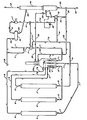
- a petroleum-derived naphtha fraction is charged to the process at a rate of about 529.8 moles per hour for a liquid hourly space velocity of about 3 hr: l by way of line 1. It is then admixed with about 3336.2 moles per hour of a hydrogen-rich gaseous stream, originating as hereinafter described, comprising about 71 mol.% hydrogen introduced from line 2 for a hydrogen to hydrocarbon ratio of about 4.5.
- the fresh feed is continued through heat exchanger 3 in line 1 wherein it is preheated to about 879°F (470°C) by indirect heat exchange with an effluent stream in line 13 recovered from reactor 11.
- Reactor 5 is the first of three reactors comprising the catalytic reforming reaction zone, each of said reactors being maintained at reforming conditions including a temperature of about 990°F. (530°C) and a pressure of about 325 psig (2240 kPa gauge). Said reforming conditions further include the utilization of a platinum-containing catalyst.
- the heated reaction mixture is transferred from said heater 4 to the initial reactor 5 via line 6.
- the effluent stream from reactor 5 is directed through line 7 to another heating coil 7a in the radiant heating section of the fired heater 4 wherein said effluent stream is reheated to provide a temperature of about 990°F (530°C) at the inlet to the catalyst bed of reactor 9.
- the reheated reactor 5 effluent stream is withdrawn from the heater 4 and introduced into the second reactor 9 by way of line 8.
- the effluent from reactor 9 is recovered through line 10 and passed to still another heating coil 10a in the radiant heating section of the fired heater 4 to be reheated before introduction into the last reactor 11 of the series of reactors which comprise the catalytic reaction zone, the reheated effluent beinq withdrawn from said heater and introduced into said reactor 11 by way of line 12.
- the effluent stream from the last reactor 11 is withdrawn through line 13 at a temperature of about 970°F (520°C) and at a rate of about 4540.5 moles per hour. Approximately 183.7 moles per hour of the last mentioned effluent stream is diverted from line 13 into line 14, and this diverted stream is passed through heat exchanger 15 associated with stabilizer column 16.
- the diverted effluent stream is utilized in said exchanger 15 to effect indirect heat exchange with a portion of the reformate product recovered from the stabilizer column 16 and recycled thereto by way of line 24.
- the amount of reactor 11 effluent that is diverted to exchanger 15 is controlled by control valve 26 in a manner hereinafter related.
- the diverted effluent stream continues through line 14 to be recombined with the main portion of the reactor 11 effluent stream from line 13, this main portion, about 4356.8 moles per hour, having been routed through heat exchanger 3 to preheat the fresh feed passing through line 1 as heretofore mentioned.
- the recombined reactor 11 effluent stream is passed through cooler 17 contained in line 14 and deposited into a separator 18 at a temperature of about 100°F (38°C).
- the separator 18 is maintained at conditions to separate a hydrogen-rich gaseous phase and a substantially liquid hydrocarbon phase, said conditions including a temperature of about 100°F. (38°C) and a pressure of about 305 psig (152 kPa gauge).
- the hydrogen-rich gaseous phase comprising about 71 mol.% hydrogen, is recovered through an overhead line 19 with one portion, about 3336.2 moles per hour, being diverted through line 2 and admixed witi the aforementioned naphtha fraction charged to the process through line 1.
- the balance of the gaseous phase from the separator 18 is discharged from the process through line 19 at a rate of about 583 moles per hour.
- the substantially liquid hydrocarbon phase is withdrawn from the separator 18 by way of line 20 and introduced into the stabilizer column 16 which is maintained at conditions of temperature and pressure to separate an overhead fraction comprising normally gaseous hydrocarbons, i.e. C 4 - hydrocarbons.
- This overhead fraction is withdrawn from the stabilizer column through line 21 at a rate approximating 122 moles per hour.
- the reformate product is withdrawn as a bottoms fraction from the stabilizer column 16 via line 22 at a rate of about 1322.3 moles per hour at a temperature of about 459°F. (237°C).
- the reformate product stream is diverted into line 23 with a predetermined amount, about 75%, of said stream being passed through line 23 and processed through heating coil 23a in the convection heating section of the fired heater 4 in indirect heat exchange with the hot combustion gases passing therethrough.
- the predetermined amount is selected to provide about 75% of the reboiler heat requirement of the stabilizer column.
- the predetermined amount may be controlled by any conventional means such as a pump or flow controller.
- the reformate product stream, after heating in the convection heating section, is returned to the stabilizer column via lines 25 and 24 at a temperature of about 503°F. (262°C).
- Control valve 26 operates to divert from line 13 sufficient quantities of reactor 11 effluent to exchanger 15 to provide the remainder of the heat necessary to obtain the predetermined stabilizer reboiler temperature. Control valve 26 further operates to maintain the predetermined reboiler temperature by varying the flow of reactor 11 effluent to exchanger 15 as necessary.
- a prior art reforming process having two separate fired heaters and a charge rate equal to that of the illustrative embodiment, would have a reforming reactants fired heater duty of about 23.7 x 10 6 BTU/hr (25.0 x 10 6 kJ/hr) and a stabilizer reboiler fired heater duty of about 5.8 x 10 6 BUT/hr (6.1 x 10 6 kJ/hr).
- An all radiant reforming reactants fired heater typically has a heater efficiency of about 54% based on the lower heating value of the fuel. Accordingly, the reforming reactants fired heater would necessarily need to fire about 43.9 x 10 6 BTU/hr (46.3 x 10 6 kJ/hr) to achieve a heater duty of 23.7 x 10 6 BTU/hr (25.0 x 10 6 kJ/hr).
- a stabilizer reboiler fired heater would typically have a heater efficiency of about 84.5 % based on a 100°F (38°C) approach temperature with the heater flue gas and the lower heating value of the fuel.
- a catalytic reforming process in accordance with the illustrative embodiment of the invention has a reforming reactants fired heater duty of about 25.0 x 10 6 BTU/hr (26.4 x 10 6 kJ/hO. It should be noted that this heater duty is larger than the corresponding heater duty of the prior art. This results from the fact that, in accordance with the invention, a portion of the reactor 11 effluent heat is utilized to reboil the stabilizer and consequently is not available to preheat the fresh feed. In the prior art process, all of the reactor effluent is available for preheat of the reactor feed and therefore the feed enters the reforming reactants fired heater at a higher inlet temperature, reducing the fired heater duty.
- the heater efficiency would be about 54% as before.
- the amount of fuel fired to achieve the heater duty is 46.2 x 10 6 BTU/hr. (48.7 x 1 0 6 kJ/hr).
- about 75% of the stabilizer reboiler duty or about 4.3 x 10 6 BrU/hr (4.5 x 10 6 kJ/hr) is picked up in the convection heating section of the fired heater.
- this heat comes from the hot combustion gases rather than by firing additional fuel. Therefore, the invention results in an overall fuel efficiency of:
- the invention results in increased efficiency even though the reforming reactants fired heater has a greater duty than the corresponding heater in the prior art process. This is because reactor 11 effluent is utilized to provide part of the heat requirements for the stabilizer and is not available to preheat the feed mixture. Accordingly, the reforming reactants fired heater duty is increased to compensate for the lower level of feed preheat. For this reason, it would not be readily apparent that utilizing the reactor effluent and convection heating section to reboil the stabilizer would lead to an increase in fuel efficiency.
- heater duty is in effect being shifted from the higher efficiency prior art stabilizer reboiler fired heater to the less efficient radiant heating section of the reforming reactants fired heater in the invention, it would not be expected that shifting heater duty from a more efficient heater to a less efficient heater would lead to the overall increase in fuel efficiency achieved by the invention.
- the portion of the reaction effluent which is subjected to the first indirect heat exchange with the reformate is a different portion than the portion of the reaction effluent which is subjected to the second indirect heat exchange with the mixture of hydrocarbonaceous feedstock and hydrogen.
- the reactor effluent heat exchange flow pattern may be arranged so that the portion of the reaction effluent which is subjected to the second indirect heat exchange with the hydrocarbonaceous feedstock and hydrogen includes at least part of the portion of the reaction effluent previously subjected to the first indirect heat exchange with the reformate.
Landscapes
- Chemical & Material Sciences (AREA)
- Oil, Petroleum & Natural Gas (AREA)
- Engineering & Computer Science (AREA)
- Chemical Kinetics & Catalysis (AREA)
- General Chemical & Material Sciences (AREA)
- Organic Chemistry (AREA)
- Production Of Liquid Hydrocarbon Mixture For Refining Petroleum (AREA)
- Organic Low-Molecular-Weight Compounds And Preparation Thereof (AREA)
Priority Applications (3)
| Application Number | Priority Date | Filing Date | Title |
|---|---|---|---|
| EP83304722A EP0134335B1 (de) | 1983-08-15 | 1983-08-15 | Verfahren zur katalytischen Reformierung |
| AT83304722T ATE28333T1 (de) | 1983-08-15 | 1983-08-15 | Verfahren zur katalytischen reformierung. |
| DE8383304722T DE3372497D1 (en) | 1983-08-15 | 1983-08-15 | A catalytic reforming process |
Applications Claiming Priority (1)
| Application Number | Priority Date | Filing Date | Title |
|---|---|---|---|
| EP83304722A EP0134335B1 (de) | 1983-08-15 | 1983-08-15 | Verfahren zur katalytischen Reformierung |
Publications (2)
| Publication Number | Publication Date |
|---|---|
| EP0134335A1 true EP0134335A1 (de) | 1985-03-20 |
| EP0134335B1 EP0134335B1 (de) | 1987-07-15 |
Family
ID=8191252
Family Applications (1)
| Application Number | Title | Priority Date | Filing Date |
|---|---|---|---|
| EP83304722A Expired EP0134335B1 (de) | 1983-08-15 | 1983-08-15 | Verfahren zur katalytischen Reformierung |
Country Status (3)
| Country | Link |
|---|---|
| EP (1) | EP0134335B1 (de) |
| AT (1) | ATE28333T1 (de) |
| DE (1) | DE3372497D1 (de) |
Cited By (1)
| Publication number | Priority date | Publication date | Assignee | Title |
|---|---|---|---|---|
| US10753646B2 (en) | 2015-06-30 | 2020-08-25 | Uop Llc | Reactor and heater configuration synergies in paraffin dehydrogenation process |
Citations (5)
| Publication number | Priority date | Publication date | Assignee | Title |
|---|---|---|---|---|
| US2943998A (en) * | 1956-08-27 | 1960-07-05 | Sinclair Refining Co | Catalytic reforming of straight-run or cracked naphtha fractions in the presence of added hydrogen in a multiple reactor fixed-bed system |
| US3572296A (en) * | 1969-07-25 | 1971-03-23 | Universal Oil Prod Co | Low pressure drop heater for fluids |
| US3882014A (en) * | 1972-10-26 | 1975-05-06 | Universal Oil Prod Co | Reaction zone effluents separation and hydrogen enrichment process |
| US4110197A (en) * | 1976-01-19 | 1978-08-29 | Uop Inc. | Hydrocarbon conversion with gravity-flowing catalyst particles |
| WO1981000415A1 (en) * | 1979-07-12 | 1981-02-19 | Cosden Technology | Catalytic reforming process |
-
1983
- 1983-08-15 DE DE8383304722T patent/DE3372497D1/de not_active Expired
- 1983-08-15 EP EP83304722A patent/EP0134335B1/de not_active Expired
- 1983-08-15 AT AT83304722T patent/ATE28333T1/de not_active IP Right Cessation
Patent Citations (5)
| Publication number | Priority date | Publication date | Assignee | Title |
|---|---|---|---|---|
| US2943998A (en) * | 1956-08-27 | 1960-07-05 | Sinclair Refining Co | Catalytic reforming of straight-run or cracked naphtha fractions in the presence of added hydrogen in a multiple reactor fixed-bed system |
| US3572296A (en) * | 1969-07-25 | 1971-03-23 | Universal Oil Prod Co | Low pressure drop heater for fluids |
| US3882014A (en) * | 1972-10-26 | 1975-05-06 | Universal Oil Prod Co | Reaction zone effluents separation and hydrogen enrichment process |
| US4110197A (en) * | 1976-01-19 | 1978-08-29 | Uop Inc. | Hydrocarbon conversion with gravity-flowing catalyst particles |
| WO1981000415A1 (en) * | 1979-07-12 | 1981-02-19 | Cosden Technology | Catalytic reforming process |
Cited By (1)
| Publication number | Priority date | Publication date | Assignee | Title |
|---|---|---|---|---|
| US10753646B2 (en) | 2015-06-30 | 2020-08-25 | Uop Llc | Reactor and heater configuration synergies in paraffin dehydrogenation process |
Also Published As
| Publication number | Publication date |
|---|---|
| EP0134335B1 (de) | 1987-07-15 |
| DE3372497D1 (en) | 1987-08-20 |
| ATE28333T1 (de) | 1987-08-15 |
Similar Documents
| Publication | Publication Date | Title |
|---|---|---|
| US4409095A (en) | Catalytic reforming process | |
| US5211838A (en) | Fixed-bed/moving-bed two stage catalytic reforming with interstage aromatics removal | |
| US5354451A (en) | Fixed-bed/moving-bed two stage catalytic reforming | |
| US4364820A (en) | Recovery of C3 + hydrocarbon conversion products and net excess hydrogen in a catalytic reforming process | |
| US8282814B2 (en) | Fired heater for a hydrocarbon conversion process | |
| KR101444487B1 (ko) | 탄화수소 변환 공정을 위한 스트림 가열 방법 | |
| US3392107A (en) | Process for reforming naphthene and paraffin containing hydrocarbons in the naphtha boiling point range in several stages to obtain a high octane gasoline | |
| US4431522A (en) | Catalytic reforming process | |
| US4627909A (en) | Dual recycle pressure-step reformer with cyclic regeneration | |
| US4441988A (en) | Catalytic reformer process | |
| WO2008060848A2 (en) | A process for heating a hydrocarbon stream entering a reaction zone with a heater convection section | |
| US6106696A (en) | Moving bed reforming process without heating between the combined feed exchanger and the lead reactor | |
| US5186909A (en) | Reaction chamber comprising a calender reactor and means for bedding the flow of a heat-carrying fluid | |
| US11084994B2 (en) | Reforming process with improved heater integration | |
| US4190520A (en) | Hydrocarbon conversion process | |
| EP0134335B1 (de) | Verfahren zur katalytischen Reformierung | |
| US9206358B2 (en) | Methods and apparatuses for heating hydrocarbon streams for processing | |
| US4073716A (en) | Process for producing synthetic natural gas and high octane motor fuel components | |
| US10947462B2 (en) | Catalyst staging in catalytic reaction process | |
| CA1209511A (en) | Catalytic reforming process | |
| FI77886B (fi) | Katalytiskt reformeringsfoerfarande. | |
| JPS6049087A (ja) | 接触改質法 | |
| EP0031847A1 (de) | Katalytisches reforming-verfahren | |
| WO2021112897A1 (en) | Staged catalytic reforming process | |
| WO1993012203A1 (en) | Fixed-bed/moving-bed two stage catalytic reforming |
Legal Events
| Date | Code | Title | Description |
|---|---|---|---|
| PUAI | Public reference made under article 153(3) epc to a published international application that has entered the european phase |
Free format text: ORIGINAL CODE: 0009012 |
|
| AK | Designated contracting states |
Designated state(s): AT BE CH DE FR GB IT LI NL SE |
|
| 17P | Request for examination filed |
Effective date: 19850731 |
|
| 17Q | First examination report despatched |
Effective date: 19860925 |
|
| GRAA | (expected) grant |
Free format text: ORIGINAL CODE: 0009210 |
|
| AK | Designated contracting states |
Kind code of ref document: B1 Designated state(s): AT BE CH DE FR GB IT LI NL SE |
|
| REF | Corresponds to: |
Ref document number: 28333 Country of ref document: AT Date of ref document: 19870815 Kind code of ref document: T |
|
| REF | Corresponds to: |
Ref document number: 3372497 Country of ref document: DE Date of ref document: 19870820 |
|
| ET | Fr: translation filed | ||
| ITF | It: translation for a ep patent filed | ||
| PLBE | No opposition filed within time limit |
Free format text: ORIGINAL CODE: 0009261 |
|
| STAA | Information on the status of an ep patent application or granted ep patent |
Free format text: STATUS: NO OPPOSITION FILED WITHIN TIME LIMIT |
|
| 26N | No opposition filed | ||
| ITTA | It: last paid annual fee | ||
| PGFP | Annual fee paid to national office [announced via postgrant information from national office to epo] |
Ref country code: AT Payment date: 19940812 Year of fee payment: 12 |
|
| PGFP | Annual fee paid to national office [announced via postgrant information from national office to epo] |
Ref country code: CH Payment date: 19940815 Year of fee payment: 12 |
|
| EAL | Se: european patent in force in sweden |
Ref document number: 83304722.8 |
|
| PG25 | Lapsed in a contracting state [announced via postgrant information from national office to epo] |
Ref country code: AT Effective date: 19950815 |
|
| PG25 | Lapsed in a contracting state [announced via postgrant information from national office to epo] |
Ref country code: LI Effective date: 19950831 Ref country code: CH Effective date: 19950831 |
|
| REG | Reference to a national code |
Ref country code: CH Ref legal event code: PL |
|
| PGFP | Annual fee paid to national office [announced via postgrant information from national office to epo] |
Ref country code: DE Payment date: 19990721 Year of fee payment: 17 |
|
| PG25 | Lapsed in a contracting state [announced via postgrant information from national office to epo] |
Ref country code: DE Free format text: LAPSE BECAUSE OF NON-PAYMENT OF DUE FEES Effective date: 20010501 |
|
| PGFP | Annual fee paid to national office [announced via postgrant information from national office to epo] |
Ref country code: FR Payment date: 20010718 Year of fee payment: 19 |
|
| PGFP | Annual fee paid to national office [announced via postgrant information from national office to epo] |
Ref country code: SE Payment date: 20010719 Year of fee payment: 19 |
|
| PGFP | Annual fee paid to national office [announced via postgrant information from national office to epo] |
Ref country code: GB Payment date: 20010720 Year of fee payment: 19 |
|
| PGFP | Annual fee paid to national office [announced via postgrant information from national office to epo] |
Ref country code: NL Payment date: 20010723 Year of fee payment: 19 |
|
| PGFP | Annual fee paid to national office [announced via postgrant information from national office to epo] |
Ref country code: BE Payment date: 20010810 Year of fee payment: 19 |
|
| REG | Reference to a national code |
Ref country code: GB Ref legal event code: IF02 |
|
| PG25 | Lapsed in a contracting state [announced via postgrant information from national office to epo] |
Ref country code: GB Free format text: LAPSE BECAUSE OF NON-PAYMENT OF DUE FEES Effective date: 20020815 |
|
| PG25 | Lapsed in a contracting state [announced via postgrant information from national office to epo] |
Ref country code: SE Free format text: LAPSE BECAUSE OF NON-PAYMENT OF DUE FEES Effective date: 20020816 |
|
| PG25 | Lapsed in a contracting state [announced via postgrant information from national office to epo] |
Ref country code: BE Free format text: LAPSE BECAUSE OF NON-PAYMENT OF DUE FEES Effective date: 20020831 |
|
| BERE | Be: lapsed |
Owner name: *UOP INC. Effective date: 20020831 |
|
| PG25 | Lapsed in a contracting state [announced via postgrant information from national office to epo] |
Ref country code: NL Free format text: LAPSE BECAUSE OF NON-PAYMENT OF DUE FEES Effective date: 20030301 |
|
| EUG | Se: european patent has lapsed | ||
| GBPC | Gb: european patent ceased through non-payment of renewal fee |
Effective date: 20020815 |
|
| PG25 | Lapsed in a contracting state [announced via postgrant information from national office to epo] |
Ref country code: FR Free format text: LAPSE BECAUSE OF NON-PAYMENT OF DUE FEES Effective date: 20030430 |
|
| NLV4 | Nl: lapsed or anulled due to non-payment of the annual fee |
Effective date: 20030301 |
|
| REG | Reference to a national code |
Ref country code: FR Ref legal event code: ST |