EP0134347B1 - Elektrodenhaltevorrichtung zur kontinuierlichen Galvanisierung - Google Patents
Elektrodenhaltevorrichtung zur kontinuierlichen Galvanisierung Download PDFInfo
- Publication number
- EP0134347B1 EP0134347B1 EP19830304937 EP83304937A EP0134347B1 EP 0134347 B1 EP0134347 B1 EP 0134347B1 EP 19830304937 EP19830304937 EP 19830304937 EP 83304937 A EP83304937 A EP 83304937A EP 0134347 B1 EP0134347 B1 EP 0134347B1
- Authority
- EP
- European Patent Office
- Prior art keywords
- support
- electrolyte
- trough
- electrodes
- gaps
- Prior art date
- Legal status (The legal status is an assumption and is not a legal conclusion. Google has not performed a legal analysis and makes no representation as to the accuracy of the status listed.)
- Expired
Links
- 238000009713 electroplating Methods 0.000 title claims description 17
- 239000003792 electrolyte Substances 0.000 claims description 28
- 239000002184 metal Substances 0.000 claims description 23
- 229910052751 metal Inorganic materials 0.000 claims description 23
- 229910000831 Steel Inorganic materials 0.000 claims description 4
- 238000000576 coating method Methods 0.000 claims description 4
- 239000010959 steel Substances 0.000 claims description 4
- 230000007797 corrosion Effects 0.000 claims description 3
- 238000005260 corrosion Methods 0.000 claims description 3
- 210000005069 ears Anatomy 0.000 claims description 3
- 239000011248 coating agent Substances 0.000 claims description 2
- 238000007747 plating Methods 0.000 description 8
- HCHKCACWOHOZIP-UHFFFAOYSA-N Zinc Chemical compound [Zn] HCHKCACWOHOZIP-UHFFFAOYSA-N 0.000 description 2
- 230000003247 decreasing effect Effects 0.000 description 2
- 238000004090 dissolution Methods 0.000 description 2
- 238000011144 upstream manufacturing Methods 0.000 description 2
- 239000002699 waste material Substances 0.000 description 2
- 229910052725 zinc Inorganic materials 0.000 description 2
- 239000011701 zinc Substances 0.000 description 2
- OKTJSMMVPCPJKN-UHFFFAOYSA-N Carbon Chemical compound [C] OKTJSMMVPCPJKN-UHFFFAOYSA-N 0.000 description 1
- 238000005266 casting Methods 0.000 description 1
- 230000008021 deposition Effects 0.000 description 1
- 238000010891 electric arc Methods 0.000 description 1
- 229910002804 graphite Inorganic materials 0.000 description 1
- 239000010439 graphite Substances 0.000 description 1
- 230000001788 irregular Effects 0.000 description 1
- 238000004519 manufacturing process Methods 0.000 description 1
- 230000003014 reinforcing effect Effects 0.000 description 1
- 238000003466 welding Methods 0.000 description 1
Images


Classifications
-
- C—CHEMISTRY; METALLURGY
- C25—ELECTROLYTIC OR ELECTROPHORETIC PROCESSES; APPARATUS THEREFOR
- C25D—PROCESSES FOR THE ELECTROLYTIC OR ELECTROPHORETIC PRODUCTION OF COATINGS; ELECTROFORMING; APPARATUS THEREFOR
- C25D7/00—Electroplating characterised by the article coated
- C25D7/06—Wires; Strips; Foils
- C25D7/0614—Strips or foils
Definitions
- This invention relates to a continuous electroplating bath having a radial cell containing consumable electrodes which are progressively renewed to correct changes in thickness of the electrodes caused by dissolution of the electrodes into the electrolyte.
- radial type electrolytic cells are used in, for example, continuous zinc plating lines for metal strips such as cold rolled thin plates.
- the cells comprise large diameter rotating drums for current supply and the lower halves of the drums are immersed in an electrolyte in the cell.
- a metal strip to be plated is trained over the immersed lower halves so that it passes into and out of the cell, during which electric current is supplied from anodes arranged in opposition to the strip and spaced therefrom to provide gaps therebetween in the radial direction of the drums.
- Such an arrangement is advantageous for plating only one surface of a strip without plating the other surface thereof. Since, however, great electric power is required for a large scale plant including such electrolytic cells, it is essential to maintain the gaps as small as possible so as to eliminate ineffective or superfluous consumption of power.
- the anodes are insoluble and, in the other, the anodes are soluble electrodes.
- the latter case is simple to maintain because the metal component is continuously replenished from the anodes and is useful particularly to obtain thick plating coatings with large electric power because there is less gas production at the electrodes.
- the anodes tend to dissolve as the plating proceeds so they become thinner and the gaps progressively enlarge thereby increasing the electric resistance and decreasing the current density and therefore progressively decreasing the plating deposition. Accordingly in a plating system using soluble electrodes, the enlarged gaps must be successively corrected in response to the consumption of the electrodes with the lapse of time.
- DE-A-2165329 there is shown an electroplating bath wherein the anode is a consumable electrode and means is provided to displace it radially towards the rotating drum so as to compensate for the enlargement of the gap caused by dissolution of the anode.
- the electrode support is generally mainly made of a graphite rod having a fairly large square cross-section (approximately 450 x 450 mm) for fulfilling conditions required for such plants, i.e. corrosion-resistance to the electrolyte, low overvoltage and low cost.
- the electrode supports are not accurately positioned at the bottom of the electrolyte bath, the gaps cannot be properly maintained while the consumable electrodes are being renewed. Accordingly, the electrode supports have been supported on stationary bases rigidly mounted on the bottom of the bath by support troughs having core members of (L-shaped) angle steels upwardly opening as shown in Figs. 1a and 1b of the accompanying drawing.
- a metal strip 3 passes along lower halves of drums 1 immersed in electrolyte T.
- the bath includes an assembly of anodes 3 which consists of groups of consumable electrodes 3' arranged side by side in opposition to metal strip 2 with gaps G relative thereto in the radial direction of the rotating drums 1.
- the anodes 3 are arranged on opposite sides of the rotating drums 1 upstream and downstream of the running direction of the metal strip 2 and are anchored on support surfaces 6 of electrode supports 5 with the aid of protrusions 4 formed on the outer surfaces of the consumable electrodes 3' so as to permit the electrodes 3' to be moved in succession along the support surfaces of the electrode supports.
- the electrode supports 5 are securely supported by support troughs 8 on the stationary bases 9 rigidly mounted on the bottom of the bath.
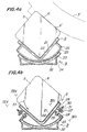
- gaps G' and G" in the proximity of the ends of the anodes 3 become relatively narrow as shown in Figs. 2a and 2b, as a result of the plating of metal strips 2 and 2' of different width.
- a continuous electroplating bath which comprises a current supply rotatable drum having a lower part immersed in electrolyte and about which a metal strip to be plated is trained so as to pass through the electrolyte, electrode supports having support surfaces and supported by a support trough mounted on a stationary base, an assembly of arcuate consumable electrodes arranged side by side along generatrices of said rotating drum and successively movable along said support surfaces whereby new consumable electrodes may be supplied at one end of the assembly and consumed electrodes may be removed from the other end of the assembly, and adjusting means for adjusting the gaps between said metal strip and said consumable electrodes characterised in that said adjusting means is provided by said support trough being rotatably mounted for tilting about said base and being fixed thereto by adjusting bolts whereby said support surfaces of said electrode support can be adjustably tilted so as to adjust said gaps.
- a continuous electroplating bath which comprises a current supply rotatable drum having a lower part immersed in electrolyte and about which a metal strip to be plated is trained so as to pass through the electrolyte, electrode supports having support surfaces and supported by a support trough mounted on a stationary base, an assembly of arcuate consumable electrodes arranged side by side along generatrices of said rotating drum and successively movable along said support surfaces whereby new consumable electrodes may be supplied at one end of the assembly and consumed electrodes may be removed from the other end of the assembly, and adjusting means for adjusting the gaps between said metal strip and said consumable electrodes characterised in that said adjusting means comprises hanging members supporting each of said electrode supports and extending upwardly from the surface of the electrolyte and extending downwardly beyond the surface of the electrolyte each member having a part in sliding engagement with a guide extending in a direction substantially parallel to a radius of said current supply rotating drum whereby sliding movement of the part with respect
- the electroplating bath comprises rotating drums 1 for supplying electric current.
- a metal strip 2 passes along the lower halves of the drums 1 below the surface of the electrolyte (not shown for clarity).
- Anodes 3 consists of groups of consumable electrodes 3' arranged side by side in opposition to and spaced from the metal strip to provide gaps extending in radial directions with respect to the rotating drums 1.
- the anodes 3 are arranged on opposite sides of an axis of the rotating drums 1 upstream and downstream of the running direction of the strip 2 and are anchored on a pair of electrode supports 5, fixed substantially in parallel with the axis of the drums 1, with the aid of protrusions 4 formed centrally on the outer surfaces of the consumable electrodes 3' so as to permit the electrodes 3' to be moved in succession along the axial direction of the electrode supports 5.
- Each of the consumable electrodes 3' is in the form of a generally arcuate zinc casting.
- Each electrode support 5 has an electrode support surface 6 immediately below the protrusions 4 of the consumable electrodes 3' for supporting the outer surfaces of the electrodes 3'.
- each electrode support is slightly angularly arranged relative to a generatrix of the rotating drum with a gradient corresponding to the consumed amount of the consumable electrode 3' during the time taken for a new electrode 3" to become a waste electrode 3"'.
- the electrode support 5 is supported with such a gradient on a support trough 8 at the bottom of the bath, which is in turn held by a stationary base 9.
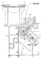
- each stationary base 9 is suspended in the electrolyte bath by the inclining lifts 11 of adjusting devices 10 arranged outside the electrolyte bath and including inclining lift guides 12.
- the arrangement shown in Fig. 3 includes bearings 13 for the drums 1, a motor 14 for driving the drums 1, a reduction gear 15, a current collector ring 16, cathode bus bars 17, current supply bars 18 forthe electrode supports 5, anode bus bars 19 and rectifiers 20.
- the support trough 8 comprises a core member 21 made of L-sectioned steel arranged so that its L-shaped groove faces upwardly and a corrosion-resistant coating such as a rubber lining 22 on the L-shaped groove and the stationary base 9 comprises a trough-shaped core member 23 and a rubber lining 24 applied thereto as shown in Figs. 4a and 4b.
- the support trough 8 is provided in the vicinity of its ends with a pair of arcuate projection pieces 25 extending downward towards and engaging with the trough-shaped stationary base 9 and lined with a.rubber lining so as to permit the support trough 8 to be rotated about the axis of the electrode support 5.
- Connecting core members 26 serve to connect ends of the arcuate projection pieces 25 to the support trough 8 at its upper edges and have a length longer than the width of the arcuate projection pieces 25 as shown in Fig. 4d.
- Each connecting core member 26 is formed with a pair of bolt apertures 27.
- the stationary base 9 is provided with a pair of ears 28 on both sides adjacent each arcuate projection piece 25.
- the support trough 8 is fixed to the stationary base 9 by means of adjusting bolts 30 with nuts 31 passing through, and fastening between, notches 29 formed in the ears 28 and the bolt apertures 27 of the connecting core members 26.
- Reference numeral 32 denotes reinforcing core members for the stationary base 9 as shown in Fig. 4b.
- the base 9 with the support trough 8 for the electrode support 5 is suspended in the electrolyte bath by the inclining lifts 11 as above mentioned.
- An end piece 40 at each end of the base 9 is provided with two clevis 11 a and 11b connected by pins 42' to lower bifurcated ends of a hanging member 42.
- the hanging member 42 is movable in the direction of the inclining lift or translation guide 12 with the aid of a lower edge 44 of a hanging portion 43 upwardly extending above the surface (not shown) of the electrolyte and further downwardly extending beyond the upper edge of the bath.
- Reference numeral 46 denotes an operating wheel for the purpose.
- the operating wheel 46 is fixedly keyed to an end of a worm shaft in a worm gear box 48 mounted on a bracket 47 fixed by welding to a sidewall w of the electrolyte bath.
- the lower edge 44 of the hanging portion 43 is connected by a pin 50' to, and embraced by, an end piece 50 of a screw threaded stem 49 actuated by a worm and a worm gear in mesh with each other in the gear box 48.
- the lower edge 44 of the hanging portion 43 is provided with a slider 51 having an inverted T-shaped cross-section slidably guided by a translation guide 52 provided on a bracket 53 fixed to the sidewall w of the bath.
- the sliding direction of the slider 51 and hence of the hanging portion 43 is arranged to be parallel to the radial axis of the current supply rotating drums 1 including the center of the electrode support 5 as shown in Fig. 5b, so that the distance between the anode 3 and the metal strip 2 can easily be adjusted without causing any unevenness in the gaps at upper and lower portions of the anode.
- the ends of the electrode supports 5 are separately adjusted so as to change the gradients relative to generatrices of the current supply rotating drums 1.
- Such an adjustment enables the electroplating apparatus to be easily applicable to metal strips of various widths and the consumable electrodes 3' to be effectively utilized so as to lower the unit price of the anodes.
- the gaps between the assembled electrodes and the metal strip to be plated can be externally adjusted according to the width direction of the strip to meet the electrolytic conditions, thereby eliminating edge-overcoating which would occur when the width of the strip is increased and making proper the rate at which the electrodes are consumed until wasted thereby lowering the unit price thereof.
Landscapes
- Chemical & Material Sciences (AREA)
- Engineering & Computer Science (AREA)
- Chemical Kinetics & Catalysis (AREA)
- Electrochemistry (AREA)
- Materials Engineering (AREA)
- Metallurgy (AREA)
- Organic Chemistry (AREA)
- Electroplating Methods And Accessories (AREA)
Claims (5)
Priority Applications (2)
| Application Number | Priority Date | Filing Date | Title |
|---|---|---|---|
| EP19830304937 EP0134347B1 (de) | 1983-08-25 | 1983-08-25 | Elektrodenhaltevorrichtung zur kontinuierlichen Galvanisierung |
| DE8383304937T DE3375932D1 (en) | 1983-08-25 | 1983-08-25 | Electrode support device for continuous electroplating bath |
Applications Claiming Priority (1)
| Application Number | Priority Date | Filing Date | Title |
|---|---|---|---|
| EP19830304937 EP0134347B1 (de) | 1983-08-25 | 1983-08-25 | Elektrodenhaltevorrichtung zur kontinuierlichen Galvanisierung |
Publications (2)
| Publication Number | Publication Date |
|---|---|
| EP0134347A1 EP0134347A1 (de) | 1985-03-20 |
| EP0134347B1 true EP0134347B1 (de) | 1988-03-09 |
Family
ID=8191265
Family Applications (1)
| Application Number | Title | Priority Date | Filing Date |
|---|---|---|---|
| EP19830304937 Expired EP0134347B1 (de) | 1983-08-25 | 1983-08-25 | Elektrodenhaltevorrichtung zur kontinuierlichen Galvanisierung |
Country Status (2)
| Country | Link |
|---|---|
| EP (1) | EP0134347B1 (de) |
| DE (1) | DE3375932D1 (de) |
Families Citing this family (2)
| Publication number | Priority date | Publication date | Assignee | Title |
|---|---|---|---|---|
| US4661213A (en) * | 1986-02-13 | 1987-04-28 | Dorsett Terry E | Electroplate to moving metal |
| CN115764428A (zh) * | 2022-12-06 | 2023-03-07 | 芜湖豫越强机械设备有限公司 | 一种活动式导电结构 |
Family Cites Families (2)
| Publication number | Priority date | Publication date | Assignee | Title |
|---|---|---|---|---|
| GB419391A (en) * | 1933-07-04 | 1934-11-12 | Arthur Ivor Wynne Williams | Improvements in or relating to the electro-deposition of metals |
| DE2165329A1 (de) * | 1971-01-04 | 1972-07-27 | Battelle Memorial Institute | Verfahren zum schnellen galvanischen Niederschlagen von Nickel |
-
1983
- 1983-08-25 EP EP19830304937 patent/EP0134347B1/de not_active Expired
- 1983-08-25 DE DE8383304937T patent/DE3375932D1/de not_active Expired
Also Published As
| Publication number | Publication date |
|---|---|
| DE3375932D1 (en) | 1988-04-14 |
| EP0134347A1 (de) | 1985-03-20 |
Similar Documents
| Publication | Publication Date | Title |
|---|---|---|
| US2544510A (en) | Apparatus and method for plating strips | |
| US2461556A (en) | Method and apparatus for the electrolytic coating of metal strip | |
| EP0554793B2 (de) | Galvanisierverfahren, Vorrichtung zur Herstellung einer Metallfolie und dabei verwendete geteilte unlösliche Elektrode | |
| US4451345A (en) | Electrode support device for continuous electroplating bath | |
| EP0134347B1 (de) | Elektrodenhaltevorrichtung zur kontinuierlichen Galvanisierung | |
| EP1699949B1 (de) | Verbesserte metallbandgalvanisierung | |
| JP3207973B2 (ja) | 電気めっき方法および電気めっき用分割型不溶性電極 | |
| EP0585586B1 (de) | Verfahren zur elektrolytischen Behandlung | |
| JP3207977B2 (ja) | 電気めっき方法および電気めっき用分割型不溶性電極 | |
| JPS58151494A (ja) | ラジアルセル型電解槽における極間調整装置 | |
| JPH04221091A (ja) | 電解銅箔の製造方法及び装置 | |
| EP1278899B1 (de) | Verfahren und vorrichtung zur elektrolytischen beschichtung eines metallbandes | |
| JP2506575B2 (ja) | 電解銅箔の製造方法及び装置 | |
| AU2001256857A1 (en) | Method and device for the electrolytic coating of a metal strip | |
| JP2003247100A (ja) | 帯状金属板の連続電気めっき方法 | |
| JPS6058317B2 (ja) | ラジアルセル型電解槽の組立て電極支持装置の通電ギャップ調整装置 | |
| JPS6033918B2 (ja) | ラジアルセル型電解槽における陽極調整装置 | |
| JPS58151497A (ja) | ラジアルセル型電気めつき装置のアノ−ドサポ−ト | |
| EP3763850A1 (de) | Anode und verfahren zur elektrolytischen abscheidung einer metallschicht auf ein metallsubstrat | |
| JPH05339797A (ja) | ラジアルセル型電気めっき装置の可溶性電極 | |
| JPH046295A (ja) | ラジアルセル型めっき用アノード | |
| JPH11124700A (ja) | 電気めっき方法および電気めっき装置 | |
| ES8407119A1 (es) | Dispositivo de soporte de electrodo para un bano galvanoplastico continuo. | |
| JPS58151495A (ja) | ラジアルセル型電気めつき装置のアノ−ドサポ−ト | |
| JPS58113398A (ja) | ラジアルセル型電気めつき装置のアノ−ドサポ−ト |
Legal Events
| Date | Code | Title | Description |
|---|---|---|---|
| PUAI | Public reference made under article 153(3) epc to a published international application that has entered the european phase |
Free format text: ORIGINAL CODE: 0009012 |
|
| 17P | Request for examination filed |
Effective date: 19840718 |
|
| AK | Designated contracting states |
Designated state(s): DE FR GB |
|
| 17Q | First examination report despatched |
Effective date: 19860421 |
|
| D17Q | First examination report despatched (deleted) | ||
| GRAA | (expected) grant |
Free format text: ORIGINAL CODE: 0009210 |
|
| AK | Designated contracting states |
Kind code of ref document: B1 Designated state(s): DE FR GB |
|
| REF | Corresponds to: |
Ref document number: 3375932 Country of ref document: DE Date of ref document: 19880414 |
|
| ET | Fr: translation filed | ||
| PLBE | No opposition filed within time limit |
Free format text: ORIGINAL CODE: 0009261 |
|
| STAA | Information on the status of an ep patent application or granted ep patent |
Free format text: STATUS: NO OPPOSITION FILED WITHIN TIME LIMIT |
|
| 26N | No opposition filed | ||
| PGFP | Annual fee paid to national office [announced via postgrant information from national office to epo] |
Ref country code: GB Payment date: 19950814 Year of fee payment: 13 |
|
| PGFP | Annual fee paid to national office [announced via postgrant information from national office to epo] |
Ref country code: DE Payment date: 19950828 Year of fee payment: 13 |
|
| PG25 | Lapsed in a contracting state [announced via postgrant information from national office to epo] |
Ref country code: GB Effective date: 19960825 |
|
| GBPC | Gb: european patent ceased through non-payment of renewal fee |
Effective date: 19960825 |
|
| PG25 | Lapsed in a contracting state [announced via postgrant information from national office to epo] |
Ref country code: DE Effective date: 19970501 |
|
| PGFP | Annual fee paid to national office [announced via postgrant information from national office to epo] |
Ref country code: FR Payment date: 19990810 Year of fee payment: 17 |
|
| PG25 | Lapsed in a contracting state [announced via postgrant information from national office to epo] |
Ref country code: FR Free format text: LAPSE BECAUSE OF NON-PAYMENT OF DUE FEES Effective date: 20010430 |
|
| REG | Reference to a national code |
Ref country code: FR Ref legal event code: ST |