EP0134503A1 - Dichtungseinrichtung für ein Absperrorgan - Google Patents
Dichtungseinrichtung für ein Absperrorgan Download PDFInfo
- Publication number
- EP0134503A1 EP0134503A1 EP84108237A EP84108237A EP0134503A1 EP 0134503 A1 EP0134503 A1 EP 0134503A1 EP 84108237 A EP84108237 A EP 84108237A EP 84108237 A EP84108237 A EP 84108237A EP 0134503 A1 EP0134503 A1 EP 0134503A1
- Authority
- EP
- European Patent Office
- Prior art keywords
- seal ring
- groove
- sealing
- sealing mechanism
- mechanism according
- Prior art date
- Legal status (The legal status is an assumption and is not a legal conclusion. Google has not performed a legal analysis and makes no representation as to the accuracy of the status listed.)
- Granted
Links
Images


Classifications
-
- F—MECHANICAL ENGINEERING; LIGHTING; HEATING; WEAPONS; BLASTING
- F16—ENGINEERING ELEMENTS AND UNITS; GENERAL MEASURES FOR PRODUCING AND MAINTAINING EFFECTIVE FUNCTIONING OF MACHINES OR INSTALLATIONS; THERMAL INSULATION IN GENERAL
- F16K—VALVES; TAPS; COCKS; ACTUATING-FLOATS; DEVICES FOR VENTING OR AERATING
- F16K1/00—Lift valves or globe valves, i.e. cut-off apparatus with closure members having at least a component of their opening and closing motion perpendicular to the closing faces
- F16K1/16—Lift valves or globe valves, i.e. cut-off apparatus with closure members having at least a component of their opening and closing motion perpendicular to the closing faces with pivoted closure-members
- F16K1/18—Lift valves or globe valves, i.e. cut-off apparatus with closure members having at least a component of their opening and closing motion perpendicular to the closing faces with pivoted closure-members with pivoted discs or flaps
- F16K1/22—Lift valves or globe valves, i.e. cut-off apparatus with closure members having at least a component of their opening and closing motion perpendicular to the closing faces with pivoted closure-members with pivoted discs or flaps with axis of rotation crossing the valve member, e.g. butterfly valves
- F16K1/226—Shaping or arrangements of the sealing
- F16K1/2263—Shaping or arrangements of the sealing the sealing being arranged on the valve seat
- F16K1/2266—Shaping or arrangements of the sealing the sealing being arranged on the valve seat and being forced into sealing contact with the valve member by a spring or a spring-like member
-
- F—MECHANICAL ENGINEERING; LIGHTING; HEATING; WEAPONS; BLASTING
- F16—ENGINEERING ELEMENTS AND UNITS; GENERAL MEASURES FOR PRODUCING AND MAINTAINING EFFECTIVE FUNCTIONING OF MACHINES OR INSTALLATIONS; THERMAL INSULATION IN GENERAL
- F16K—VALVES; TAPS; COCKS; ACTUATING-FLOATS; DEVICES FOR VENTING OR AERATING
- F16K5/00—Plug valves; Taps or cocks comprising only cut-off apparatus having at least one of the sealing faces shaped as a more or less complete surface of a solid of revolution, the opening and closing movement being predominantly rotary
- F16K5/06—Plug valves; Taps or cocks comprising only cut-off apparatus having at least one of the sealing faces shaped as a more or less complete surface of a solid of revolution, the opening and closing movement being predominantly rotary with plugs having spherical surfaces; Packings therefor
- F16K5/0663—Packings
- F16K5/0673—Composite packings
Definitions
- the present invention relates generally to sealing mechanisms, and more particularly to seal rings having application to valves.
- the present invention is an improvement over prior art high-performance sealing mechanisms which have attempted to provide leak proof sealing and which continue to function even in the event of and following high temperature situations or fire.
- the need for such sealing mechanisms is particularly acute in the petroleum industry, where petroleum drilling and processing are subject, on occasion, to very high temperatures or even combustion of the material handled.
- a prior art invention of Simmons et al, U.S. Patent No. 4,113,268, provides a fire proof, bubble-tight sealing mechanism which utilizes a two stage arrangement.
- a soft primary seal for example of teflon, is inserted in the rib of a metal seal ring for contact with the complementary surface of a closure member.
- the teflon material extending radially inward beyond the metal rib, provides a bubble-tight seal under normal conditions. In the event of fire, the teflon is destroyed. Subsequently, the metal rib of the seal ring dynamically moves into position to form a secondary or metal to metal seal.
- Benware in U.S. Patent No. 3,642,248, discloses a valve sealing mechanism which discloses the type of dynamic sealing utilized in a preferred embodiment of the present invention.
- the seal ring is fitted within a circumferential groove of a body member. A portion of the seal ring extends out of the groove, radially inward, for mating engagement with a closure member or disk.
- the seal ring is arranged within the groove for moveable adjustment in response to the pressure of the system.
- the seal ring of Benware in a preferred embodiment, has a backing ring which is held within the groove, beneath the seal ring. This backing ring provides a preloaded sealing force for the side-sealing of the seal ring with the walls of the groove.
- the seal ring of Benware is preferably constructed of a soft material such as teflon.
- a second embodiment discloses a metal seal ring.
- a pair of inclined surfaces at the sides of the seal ring abut the lateral sides of the groove and are preloaded by being of a slightly greater dimension than the width of the groove.
- the front of the seal ring is curved slightly and concavely in relation to the disk surface. This causes the upstream and downstream edges of the seating surface of the seal ring to bite against the disk surface when the seal ring is pushed against the disk.
- the present invention has important advantages over the prior art. It provides essentially leak proof sealing in a fire proof metal to metal seal.
- the seal ring may be manufactured conveniently and inexpensively. Due to its metal construction, it may be formed rather than machined and does not require the insertion of a soft plastic part.
- the metal seal ring design results in high-strength, resilient characteristics which provide for superior sealing and durability.
- the present invention can be employed in many kinds of systems which contain fluids at differing pressures, such as hydraulic or pneumatic systems where it is desirable to provide a seal in one or more portions thereof.
- hydraulic or pneumatic systems where it is desirable to provide a seal in one or more portions thereof.
- components which can be opened or closed, i.e., positioned so that fluid flow is permitted or obstructed.
- the present invention is intended to prevent leakage of fluid when such components are in a closed position, while, without diminishing the efficiency of the seal thus created, permitting such components to be opened with a minimum of force.
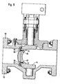
- the trunnion valve in Figure 1 includes a valve body 1 in the form of a flat annular wafer having an internal passageway 2 with an inlet 3 and an outlet 4.
- the downstream or outlet face 5 of the valve body is counterbored with an annular recess 6 for flush mounting a retainer ring 7 by means of flat head machine screws 8.
- Retainer ring 7 serves to hold a sealing ring 9 within a circumferential groove 11 machined in the downstream edge of passageway 2.
- a valve disk 12 having a circumferential sealing surface 13 is adapted to be mounted within passageway 2 for rotation about a diametrical axis between an open position in which the valve disk is substantially parallel to the axis of passageway 2 and a shut position in which the valve disk is substantially perpendicular to the passageway axis and sealing surface 13 makes mating contact with the seal ring 9.
- Means for pivotally mounting the valve disk in the passageway for rotation between the open and shut positions includes a valve stem 14 mounted in upper and lower bushings 15 and 16 for rotation within a blind hole 17 bored diametrically through the valve body.
- Valve stem 14 passes through a hole 18 drilled through a diametrical boss 19 on the upstream face of the valve disk, which is locked to the stem by pins 20.
- valve stem 14 Leakage past the upper end of valve stem 14 is prevented by conventional stem packing means including spacer 21 and resilient packing rings 22, which are compressed in hole 17 against the top of bushing 15 by forcing gland 23 and follower 24 downward by means of nuts 25 screwed down on studs 26.
- Valve stem 14 is rotated in its bushings by a handle or motor drive (not shown) attached to the squared upper end 27 of the valve stem.
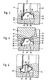
- Figure 2 shows a section of the assembled seating arrangement of the valve of Figure 1, but showing in detail a preferred embodiment of the seal ring of the present invention.
- the combination, in general, of a seal ring within a groove is described in the previously mentioned Benware U.S. Patent No. 3,642,248, the disclosure of which is hereby incorporated by reference in the present specification.
- the valve comprises a groove 27 having a base 28 and sidewalls 29,30.
- the groove 27 in the preferred embodiment extends annularly since the closure member is a circular disk, in the valve described above. It is noted, however, that the present embodiment is not meant to limit the scope of the invention and the closure member may alternatively be, for example, a door mounted in a rectilinear frame.
- the mouth of the groove 27 is defined by a pair of lip flanges 31, 32 extending from the sidewalls 29,30 respectively.
- the groove by means of said lip flanges fittingly hold the seal ring 33, the seating portion 34 of which projects through the mouth of said groove.
- the seating portion 34 of said seal ring is thus adapted to extend radially inward for sealing engagement with the complementary surface of the disk 35.
- the seating portion 34 of the seal ring 33 is convexly shaped with respect to the axis of the valve passageway.
- the seal ring 33 is provided with shoulder portions 36, 37, which integrally extend on either side from said seating portion.
- the anterior surfaces of said shoulder portions 36, 37 are adapted to abut against the lip flanges 31, 32 such that said seal ring is held within said groove.
- the lateral surfaces of said shoulder portions are thus contained within said groove, abut the sidewalls 29, 30, and are slideably engageable therewith.
- the shoulder portions are resiliently biased against the sidewalls 29, 30, which serves to impart side-sealing contact to the engagement of the seal ring with the sides of the groove, as described hereafter.
- the resilient bias of the seal ring 33 is achieved by the latter being of greater width than the circumferential groove 27 in which it is fitted. Consequently, said seal ring is compressed like a spring when held in said groove.
- seal ring Variations in the dimensions of the seal ring are permitted to the extent that a satisfactory pre-loaded fit is obtained. However, the seal ring should be capable of returning to its uncompressed width so that the lateral side-sealing forces are maintained sufficiently high.
- the surface of the seating portion 34 of the seal ring 33 is intended to engage disk 35 (Figure 3), in order to seal against leakage.
- Said disk 35 includes a sealing surface 38 engageable with said seating surface of said seal ring.
- the disk 35 is representative of a great variety of components which are intended to be sealed in a pressurized system.
- disk 35 is a valve disk which is to be sealed against hydraulic or pneumatic leakage and is slidably engageable or otherwise abuttable against the seating portion 34 of seal ring 33.
- Said disk could also be a cover or hatch intended to be sealed against such leakage, it being understood that the specific reference herein to the nature of the disk 35 is only illustrative and is not intended as a limitation of the nature or application of this invention.
- FIG. 4 A second embodiment of the present invention is shown in Figure 4.
- a seal ring similar to the one shown in Figures 2 and 3 is shown, except that legs 43,44 integrally extend from each of the shoulder portions.
- Each leg extends generally in the posterior direction, with respect to the passageway of the valve, and together obliquely converge toward a radial axis of said seal ring.
- feet 45, 46 contact the base 28 of said groove.
- the seal ring is confined in the circumferential groove 27 disposed in the body of the valve.
- the seal ring is a hollow toroid constructed of metal and having the cross-sectional shape shown in Figure 5.
- the seal ring is comprised of a front seating portion 34, shoulder portions 36, 37 and a back portion 47.
- the front seating portion abuts the sealing surface 38 of the disk 35 when the latter is in the closed position.
- the seating portion is integrally joined to the shoulder portions which are held within the circumferential groove by flange lips 31 and 32.
- the shoulder portions are integrally joined at each of the ends opposite the seating portion by the back portion, the seal ring thereby forming one continuous surface enclosing a toroidal cavity 48.
- the back portion 47 forms a convex surface with respect to the base of the circumferential groove and abuts the base of the circumferential groove when the seal ring is in sealing engagement with the disk. The summit of said convex surface contacts the base of the groove as is evident from Figure 5.
- the seal ring is modified from the embodiment shown in Figure 5 by having dual protuberances 49 and 50, convex with respect to the base of the groove. These protuberances contact said base at two isolated circumferential locations when the seal ring is in mating engagement with the disk.
- the seal ring of Figure 6 is otherwise identical to the seal ring of Figure 5.
- Figure 7 illustrates a further preferred embodiment of the instant invention wherein the seal ring 33 is provided with two protuberances 52 and 53 at the mating surface between the seal ring 33 and the mating sealing surface, disk 35, such that a groove 54 is provided therebetween.
- the purpose of the groove is to provide a recessed space in which an insert material (not shown) can be placed.
- the insert material can be metallic or non-metallic and should be selected based upon its wear and sealing properties. Possible candidates for filler materials include silver, copper, asbestos, graphite, plastics and elastomers.
- the insert can be designed with tapered sides and the metal seal pinched or formed around the insert to lock it firmly in place. The insert enhances the seal between the seal and its mating sealing surface and offers improved cycle life.
- the back portion 47 of the seal ring is shown in contact with the base of the circumferential groove. This is not a requirement, however, and embodiments of the invention are contemplated where the back portion 47 of the seal need not necessarily be in contact with the base of the circumferential groove.
- seal rings shown in Figures 5, 6 and 7 may be obtained by reforming a hollow metal 0-ring. Hence, the seal ring may be conveniently and inexpensively manufactured.
- the hollow reformed O-rings are relatively thin walled for high resilience.
- the degree of stiffness or resiliency may be controlled by varying the thickness of the seal ring wall. Consequently, spring-like forces may be achieved when the seal ring of the present invention is compressed.
- the strength and resilience of the seal rings shown in Figures 5, 6 and 7 may be enhanced by pressurization of the interior or toroidal cavity of the seal ring.
- the seal ring may be pressurized by injecting a gas into the cavity of the 0-ring during fabrication.
- the interior of the seal ring may be pressurized by providing optional apertures 51 ( Figure 5) in the upstream wall of the seal ring. System fluid pressure is thereby permitted to enter the interior of the seal ring.
- purge holes may be placed in various other locations along the seal, e.g. in the back of the seal or in either side of the seal, in any of the embodiments of Figures 5, 6 and 7, ' so that the same would result in improved performance of the seal.
- the continuous cross-section of the seal ring has the advantage of providing stability to the sealing mechanism, particularly at elevated temperatures. Due to the continuous configuration of the seal ring, the bearing force remains unaffected by high temperatures, whereas other seal rings may tend to loose their sealing force on account of thermal expansion.
- All of the seal ring embodiments of the present invention are preferably composed of a high temperature resistant, high corrosion resistant metal alloy exhibiting high yield strength and a satisfactory modulus of elasticity.
- High alloy materials such as Inconels or Hastalloys may be used.
- Stainless steel or bronze may also be employed.
- the seal rings of the various embodiments of the present invention are formed with a seating portion which is convex with respect to the sealing surface of the closure member.
- the convex seating portion is integrally joined on both sides through an inflection point 39 to a pair of lateral shoulder portions 36, 37 which are convex with respect to the sidewalls of the groove.
- inflection is meant a change of curvature, with respect to a fixed line intersecting the juncture of the seating portion and shoulder portion, said curvature serving to continuously join the convex surfaces of said seating portion and said shoulder portion.
- bubble-tight sealing may be obtained by applying a suitable coating to the seating portion of the metal seal ring or to the complementary sealing surface of the closure member.
- a suitable coating for example, a thin layer of teflon may be adhesively coated on the seating portion of the seal ring.
- the seating surface may be coated or plated with such materials as gold, silver, copper, nickel, graphite, or other coatings that would enhance performance.
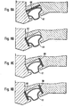
- a gasket or gaskets may be inserted into the seal groove, between the seal ring and surface of the groove, to improve the performance of the seal by insuring more consistent leakage results.
- the use of such seals is illustrated in the drawings of Figures 8A through 8D, which, respectively, show gaskets 60 between the back portion of the seal and the base of the groove ( Figure 8A); between alternate shoulder portions of the seal and their respective sides of the groove ( Figures 8B and 8C); and simultaneously between both shoulder portions and their respective sides of the groove ( Figure 8D).
- Such a gasket may comprise materials such as graphite, asbestos, rubber or other materials. Non-asbestos gasket materials are particularly comprehended for future use.
- Alternate embodiments of the invention further include those embodiments where the seal is placed on the valve closure member as opposed to its being placed in the valve body.
- Figure 9 which illustrates a ball valve, with a sealing mechanism according to the instant invention, wherein the seal 91 is placed in the ball segment 95. To effect closure, the ball segment 95 is rotated until the seal 91 mounted thereon is compressed against the ball valve body 93.
- the ball valve utilized may be a six inch 600 ANSI segmented ball valve.
- the seal may be secured within the groove by a ring 98 and fastening means 96, 97 such as metal screws. The chamfer around the periphery of the ring may be machined smooth.
- valve body may be modified at the sealing surface to contain a removable metal ring 99 with an erosion, corrosion and wear resistant surface coating.
- a removable metal ring 99 with an erosion, corrosion and wear resistant surface coating.
- Such a ring may be held in place by an interference fit, wherein the diameter of the outer retaining body is greater than the diameter of the ring 99.
- seal ring 33 in cooperation with the groove 27, is adapted to communicate high fluid pressure from the region upstream of disk 35 to the interior of the groove 40. This fluid pressure is employed to aid in urging the seal ring 33 and hence seating surface 34 against disk 35 to maintain seal efficiency and avoid leakage therebetween.
- the operation of the seal ring in response to pressure is as follows. Referring to Figure 3, when there is a sufficient pressure differential between regions 41 and 42, pressure will be introduced into the interior region 40 of the groove. Because the shape of the seal ring 33 is adapted for flexibility, the fluid pressure is permitted to enter the interior region even though the shoulder portions 36, 37 normally abut the sidewalls of the groove. The system pressure in the interior region 40 will act upon the exposed back surface of the seal ring so as to urge it toward the complementary surface of the circumferential edge of the disk.
- Said system pressure thus creates a thrust beneath said seal ring 33 which achieves enhanced sealing contact with the disk.
- the pressure exerted by the seal ring against the disk is referred to as the bearing pressure.
- This bearing pressure is concentrated along the summit of the convexly shaped seating portion of the seal ring.
- the sealing contact, between the sealing surface of the disk and the seating portion of the seal ring, is maintained along a circumferential, relatively narrow surface. This is particularly the case when, as shown in Figures 3 and 4, the sealing surface of the disk is convexly shaped with respect to the seal ring, hence resulting in the meeting of opposing convex surfaces.
- the disk when closed exerts a generally radial force against the seating portion of the seal ring. This radial force is resisted by the bearing pressure transmitted through the seal ring, as explained above.
- the disk in the closed position, pushing against the seating portion of the seal ring, would expand the distance between the shoulder portions were the latter not constrained by the sidewalls of the groove. This counteraction between the lateral and radial forces serves to further increase the side preload of the seal ring against the sidewalls of the groove.
- the legs 43, 44 of the seal ring include feet 45, 46 which contact the base of the groove. This contact further contributes to the sealing by providing a secondary seal.
- seal rings of Figures 5 and 6 are not completely analogous to the previous embodiments.
- the seal ring is similarly partially confined within the circumferential groove in the valve body, there is comparatively less space for radial adjustment of the seal ring within the groove.
- the back portion of the seal ring must abut the base of the circumferential groove when the disk is moved to the closed position.
- the closure of the disk causes a radial force to bear against the seating portion of the seal ring. This force would tend to expand the axial diameter of the seal ring if it were not limited by the side walls of the circumferential groove.
- This sealing contact is capable of withstanding and responding to system pressures which would otherwise separate the mating surfaces and break the seal.
- the sealing mechanism responds to the pressure within the system to strengthen the sealing forces in direct proportion to said pressure so that said sealing forces are at all times greater or equal to the resultant forces which urge the mating surfaces apart.
- the embodiment of Figure 7 is similar in operation to the embodiments of Figures 5 and 6, however, with the embodiment of Figure 7, the filler material placed within groove 54 further enhances the seal between the seal ring and its mating sealing surface.
- a further difference in the operation of the embodiment of Figure 7 is that the back portion of the seal ring of this embodiment need not necessarily contact the base of the circumferential groove during operation.
- a gasket in embodiments of the instant invention may in operation serve to improve (or insure more consistent) leakage results.
- the presence of the gasket serves not only to lessen leakage at the point of contact where the seal meets the gasket and where the gasket meets the groove, there providing a typical gasket function, but it also results in a tighter seal at the remaining contact points of the sealing mechanism.
- the gasket 60 is placed between the back of the seal and the base of the groove, the consequent lessening of area available for expansion of the seal when pressure is applied thereto will result in increased contact pressure at the points where the seal shoulders contact the sides of the groove.
- valve Although the operation of the valve was described for illustrative purposes in a system having a greater pressure in the upstream passageway, it will be readily understood that the sealing mechanism of the present invention will accomplish sealing action, in an analogous manner, if the higher pressure originates from the other direction.
- a trunion valve according to the present preferred embodiment shown in Figure 2 and of the same size and pressure exhibits a typical leakage rate of 1.45 SCFH (average of three tests).
- the valves having the seal ring of the present invention are shown to have superior sealing effectiveness. These valves evidenced a leakage rate of no more than 0.145 standard cubic feet per hour per inch of valve diameter. In comparison, the prior art valve showed leakage rates exceeding 5.4 standard cubic feet per hour per inch of valve diameter.
- the seal ring of the present invention achieves an extraordinary degree of sealing effectiveness in view of its simple and economical design.
- the all metal nature of the seal ring renders unnecessary the teflon inserts utilized in the prior art. Hence, destruction of the seal by fire, or the necessity for a back-up or secondary seal is obviated.
- the ability of the seal ring to function under high temperature conditions responds to the need for a fire safe sealing mechanism for a butterfly valve usable in such industrial fields of applications as petroleum processing.
- the metal seal ring may be inexpensively and conveniently manufactured by forming rather than machining. This permits the use of high alloy metals having high strength and resilience. Hence, the construction of the seal ring of the present invention assures reliability and durability.
Landscapes
- Engineering & Computer Science (AREA)
- General Engineering & Computer Science (AREA)
- Mechanical Engineering (AREA)
- Lift Valve (AREA)
- Gasket Seals (AREA)
- Discharge Heating (AREA)
- Processing Of Solid Wastes (AREA)
- Push-Button Switches (AREA)
- Sealing Devices (AREA)
Priority Applications (1)
| Application Number | Priority Date | Filing Date | Title |
|---|---|---|---|
| AT84108237T ATE63623T1 (de) | 1983-07-13 | 1984-07-12 | Dichtungseinrichtung fuer ein absperrorgan. |
Applications Claiming Priority (4)
| Application Number | Priority Date | Filing Date | Title |
|---|---|---|---|
| US51335383A | 1983-07-13 | 1983-07-13 | |
| US513353 | 1983-07-13 | ||
| US61174184A | 1984-05-18 | 1984-05-18 | |
| US611741 | 1984-05-18 |
Publications (2)
| Publication Number | Publication Date |
|---|---|
| EP0134503A1 true EP0134503A1 (de) | 1985-03-20 |
| EP0134503B1 EP0134503B1 (de) | 1991-05-15 |
Family
ID=27057833
Family Applications (1)
| Application Number | Title | Priority Date | Filing Date |
|---|---|---|---|
| EP84108237A Expired EP0134503B1 (de) | 1983-07-13 | 1984-07-12 | Dichtungseinrichtung für ein Absperrorgan |
Country Status (6)
| Country | Link |
|---|---|
| EP (1) | EP0134503B1 (de) |
| JP (1) | JPH0446151Y2 (de) |
| CN (1) | CN1004021B (de) |
| AT (1) | ATE63623T1 (de) |
| CA (1) | CA1240970A (de) |
| DE (1) | DE3484580D1 (de) |
Cited By (2)
| Publication number | Priority date | Publication date | Assignee | Title |
|---|---|---|---|---|
| CN116171358A (zh) * | 2020-06-30 | 2023-05-26 | 亚当斯有限公司 | 用于瓣阀的金属密封件 |
| CN116513368A (zh) * | 2023-07-05 | 2023-08-01 | 常州耐普德新能源科技有限公司 | 一种舱室微压的密封装置及工作方法 |
Families Citing this family (2)
| Publication number | Priority date | Publication date | Assignee | Title |
|---|---|---|---|---|
| DE102011101453A1 (de) | 2011-05-12 | 2012-11-15 | Ekkehard Schneider | Kugelhahnventil |
| CN102322299B (zh) * | 2011-08-25 | 2014-03-26 | 上海电气电站设备有限公司 | 汽缸中分面密封结构及密封方法 |
Citations (7)
| Publication number | Priority date | Publication date | Assignee | Title |
|---|---|---|---|---|
| US1043065A (en) * | 1910-06-14 | 1912-11-05 | Arthur W Cash | Valve. |
| FR2015867A1 (de) * | 1968-08-19 | 1970-04-30 | Grove Valve & Regulator Co | |
| DE2038905A1 (de) * | 1969-08-06 | 1971-02-18 | Hills Mccanna Co | Ventil mit verbessertem Dichtring |
| US3642248A (en) * | 1969-05-07 | 1972-02-15 | Allen & Co Fof Proprietary Fun | Sealing mechanism |
| US4113268A (en) * | 1977-03-15 | 1978-09-12 | Posi-Seal International, Inc. | Extended temperature range valve seal |
| DE2916984A1 (de) * | 1978-04-26 | 1979-11-08 | Fmc Corp | Sitz fuer ein absperrelement eines absperrorgans und absperrorgan mit einem solchen sitz |
| US4277047A (en) * | 1979-01-30 | 1981-07-07 | Tokyo Koso Kabushiki Kaisha | Metallic sealing device for valve |
Family Cites Families (1)
| Publication number | Priority date | Publication date | Assignee | Title |
|---|---|---|---|---|
| FR2497905A2 (fr) * | 1981-01-13 | 1982-07-16 | Amri | Double joint torique flexible |
-
1984
- 1984-07-12 DE DE8484108237T patent/DE3484580D1/de not_active Expired - Lifetime
- 1984-07-12 AT AT84108237T patent/ATE63623T1/de not_active IP Right Cessation
- 1984-07-12 EP EP84108237A patent/EP0134503B1/de not_active Expired
- 1984-07-12 CA CA000458724A patent/CA1240970A/en not_active Expired
-
1985
- 1985-05-20 CN CN85103937.5A patent/CN1004021B/zh not_active Expired
-
1990
- 1990-03-19 JP JP1990028112U patent/JPH0446151Y2/ja not_active Expired
Patent Citations (7)
| Publication number | Priority date | Publication date | Assignee | Title |
|---|---|---|---|---|
| US1043065A (en) * | 1910-06-14 | 1912-11-05 | Arthur W Cash | Valve. |
| FR2015867A1 (de) * | 1968-08-19 | 1970-04-30 | Grove Valve & Regulator Co | |
| US3642248A (en) * | 1969-05-07 | 1972-02-15 | Allen & Co Fof Proprietary Fun | Sealing mechanism |
| DE2038905A1 (de) * | 1969-08-06 | 1971-02-18 | Hills Mccanna Co | Ventil mit verbessertem Dichtring |
| US4113268A (en) * | 1977-03-15 | 1978-09-12 | Posi-Seal International, Inc. | Extended temperature range valve seal |
| DE2916984A1 (de) * | 1978-04-26 | 1979-11-08 | Fmc Corp | Sitz fuer ein absperrelement eines absperrorgans und absperrorgan mit einem solchen sitz |
| US4277047A (en) * | 1979-01-30 | 1981-07-07 | Tokyo Koso Kabushiki Kaisha | Metallic sealing device for valve |
Cited By (3)
| Publication number | Priority date | Publication date | Assignee | Title |
|---|---|---|---|---|
| CN116171358A (zh) * | 2020-06-30 | 2023-05-26 | 亚当斯有限公司 | 用于瓣阀的金属密封件 |
| CN116513368A (zh) * | 2023-07-05 | 2023-08-01 | 常州耐普德新能源科技有限公司 | 一种舱室微压的密封装置及工作方法 |
| CN116513368B (zh) * | 2023-07-05 | 2023-08-29 | 常州耐普德新能源科技有限公司 | 一种舱室微压的密封装置及工作方法 |
Also Published As
| Publication number | Publication date |
|---|---|
| ATE63623T1 (de) | 1991-06-15 |
| JPH0446151Y2 (de) | 1992-10-29 |
| DE3484580D1 (de) | 1991-06-20 |
| JPH02135771U (de) | 1990-11-13 |
| CN85103937A (zh) | 1986-12-03 |
| CA1240970A (en) | 1988-08-23 |
| EP0134503B1 (de) | 1991-05-15 |
| CN1004021B (zh) | 1989-04-26 |
Similar Documents
| Publication | Publication Date | Title |
|---|---|---|
| US4744572A (en) | All-metal, valve sealing mechanism | |
| US4113268A (en) | Extended temperature range valve seal | |
| US3986699A (en) | Positive shut-off seal | |
| US4398695A (en) | Metal seal structure | |
| US3960364A (en) | High pressure tight shutoff valve seal | |
| US3131906A (en) | Valve seat | |
| US3883112A (en) | Plug valve having composite seat element | |
| US3455534A (en) | Valve and two-piece seat assembly | |
| US4396199A (en) | Fluid pressure sealing member for a valve | |
| US4378104A (en) | Fluid-pressure-loaded seal for butterfly valves | |
| US4155536A (en) | Seat ring assembly for a valve | |
| US4418889A (en) | Fire safe seat for a valve | |
| EP0675304B1 (de) | Dichtung | |
| EP0025402B1 (de) | Ventil für Tieftemperaturbetrieb und Dichtung dafür | |
| GB1571875A (en) | Extendend temperature range valve seal | |
| EP0146568B1 (de) | Ventildichtung für kryogene verwendung | |
| US4401292A (en) | Valve seat structure | |
| US4341233A (en) | Fire safe seat for a rotary valve | |
| CA1240970A (en) | Valve sealing mechanism | |
| US4335748A (en) | Bidirectional control valve | |
| US3722859A (en) | Ball valve seal for high temperature operation | |
| US5478047A (en) | Flexible seating structure for valves | |
| US3373968A (en) | Between-flange ball valve with slidable seats | |
| GB2140896A (en) | Ball valve seals | |
| CA1208191A (en) | Bidirectional valve seal |
Legal Events
| Date | Code | Title | Description |
|---|---|---|---|
| PUAI | Public reference made under article 153(3) epc to a published international application that has entered the european phase |
Free format text: ORIGINAL CODE: 0009012 |
|
| AK | Designated contracting states |
Designated state(s): AT BE CH DE FR GB IT LI LU NL SE |
|
| 17P | Request for examination filed |
Effective date: 19850920 |
|
| 17Q | First examination report despatched |
Effective date: 19860613 |
|
| GRAA | (expected) grant |
Free format text: ORIGINAL CODE: 0009210 |
|
| AK | Designated contracting states |
Kind code of ref document: B1 Designated state(s): AT BE CH DE FR GB IT LI LU NL SE |
|
| REF | Corresponds to: |
Ref document number: 63623 Country of ref document: AT Date of ref document: 19910615 Kind code of ref document: T |
|
| ITF | It: translation for a ep patent filed | ||
| REF | Corresponds to: |
Ref document number: 3484580 Country of ref document: DE Date of ref document: 19910620 |
|
| ET | Fr: translation filed | ||
| PLBE | No opposition filed within time limit |
Free format text: ORIGINAL CODE: 0009261 |
|
| STAA | Information on the status of an ep patent application or granted ep patent |
Free format text: STATUS: NO OPPOSITION FILED WITHIN TIME LIMIT |
|
| 26N | No opposition filed | ||
| PGFP | Annual fee paid to national office [announced via postgrant information from national office to epo] |
Ref country code: AT Payment date: 19930611 Year of fee payment: 10 |
|
| PGFP | Annual fee paid to national office [announced via postgrant information from national office to epo] |
Ref country code: CH Payment date: 19930616 Year of fee payment: 10 |
|
| PGFP | Annual fee paid to national office [announced via postgrant information from national office to epo] |
Ref country code: BE Payment date: 19930621 Year of fee payment: 10 |
|
| PGFP | Annual fee paid to national office [announced via postgrant information from national office to epo] |
Ref country code: LU Payment date: 19930701 Year of fee payment: 10 |
|
| PGFP | Annual fee paid to national office [announced via postgrant information from national office to epo] |
Ref country code: NL Payment date: 19930731 Year of fee payment: 10 |
|
| EPTA | Lu: last paid annual fee | ||
| PG25 | Lapsed in a contracting state [announced via postgrant information from national office to epo] |
Ref country code: LU Free format text: LAPSE BECAUSE OF NON-PAYMENT OF DUE FEES Effective date: 19940712 Ref country code: AT Effective date: 19940712 |
|
| PG25 | Lapsed in a contracting state [announced via postgrant information from national office to epo] |
Ref country code: LI Effective date: 19940731 Ref country code: CH Effective date: 19940731 Ref country code: BE Effective date: 19940731 |
|
| BERE | Be: lapsed |
Owner name: POSI-SEAL INTERNATIONAL INC. Effective date: 19940731 |
|
| EAL | Se: european patent in force in sweden |
Ref document number: 84108237.3 |
|
| PG25 | Lapsed in a contracting state [announced via postgrant information from national office to epo] |
Ref country code: NL Effective date: 19950201 |
|
| NLV4 | Nl: lapsed or anulled due to non-payment of the annual fee | ||
| REG | Reference to a national code |
Ref country code: CH Ref legal event code: PL |
|
| PGFP | Annual fee paid to national office [announced via postgrant information from national office to epo] |
Ref country code: GB Payment date: 19970703 Year of fee payment: 14 |
|
| PGFP | Annual fee paid to national office [announced via postgrant information from national office to epo] |
Ref country code: FR Payment date: 19970709 Year of fee payment: 14 |
|
| PGFP | Annual fee paid to national office [announced via postgrant information from national office to epo] |
Ref country code: SE Payment date: 19970716 Year of fee payment: 14 |
|
| PGFP | Annual fee paid to national office [announced via postgrant information from national office to epo] |
Ref country code: DE Payment date: 19970718 Year of fee payment: 14 |
|
| PG25 | Lapsed in a contracting state [announced via postgrant information from national office to epo] |
Ref country code: GB Free format text: LAPSE BECAUSE OF NON-PAYMENT OF DUE FEES Effective date: 19980712 |
|
| PG25 | Lapsed in a contracting state [announced via postgrant information from national office to epo] |
Ref country code: SE Free format text: LAPSE BECAUSE OF NON-PAYMENT OF DUE FEES Effective date: 19980713 |
|
| GBPC | Gb: european patent ceased through non-payment of renewal fee |
Effective date: 19980712 |
|
| EUG | Se: european patent has lapsed |
Ref document number: 84108237.3 |
|
| PG25 | Lapsed in a contracting state [announced via postgrant information from national office to epo] |
Ref country code: FR Free format text: LAPSE BECAUSE OF NON-PAYMENT OF DUE FEES Effective date: 19990331 |
|
| PG25 | Lapsed in a contracting state [announced via postgrant information from national office to epo] |
Ref country code: DE Free format text: LAPSE BECAUSE OF NON-PAYMENT OF DUE FEES Effective date: 19990501 |
|
| REG | Reference to a national code |
Ref country code: FR Ref legal event code: ST |