EP0134537A2 - Véhicule à roues actionnées au pied - Google Patents
Véhicule à roues actionnées au pied Download PDFInfo
- Publication number
- EP0134537A2 EP0134537A2 EP84109158A EP84109158A EP0134537A2 EP 0134537 A2 EP0134537 A2 EP 0134537A2 EP 84109158 A EP84109158 A EP 84109158A EP 84109158 A EP84109158 A EP 84109158A EP 0134537 A2 EP0134537 A2 EP 0134537A2
- Authority
- EP
- European Patent Office
- Prior art keywords
- impeller according
- rockers
- impeller
- saddle
- wheels
- Prior art date
- Legal status (The legal status is an assumption and is not a legal conclusion. Google has not performed a legal analysis and makes no representation as to the accuracy of the status listed.)
- Granted
Links
Images
Classifications
-
- B—PERFORMING OPERATIONS; TRANSPORTING
- B62—LAND VEHICLES FOR TRAVELLING OTHERWISE THAN ON RAILS
- B62K—CYCLES; CYCLE FRAMES; CYCLE STEERING DEVICES; RIDER-OPERATED TERMINAL CONTROLS SPECIALLY ADAPTED FOR CYCLES; CYCLE AXLE SUSPENSIONS; CYCLE SIDECARS, FORECARS, OR THE LIKE
- B62K17/00—Cycles not otherwise provided for
Definitions
- the invention relates to an impeller according to the preamble of the main claim.
- the trolley is considered the forerunner of the bicycles and has a saddle which remains rigid at a certain height and which, in order to allow a certain step size when running, must be arranged relatively low.
- the feet are very relieved of their body weight when they are far forward or far back, but in the middle, where the distance between the saddle and the ground is significantly less than the leg length of the runner, the legs have to do almost that carry entire body weight.
- the object on which the invention is based is to provide an aid for runners with which the feet are relieved of the load on the body and in which the natural course of movement can be largely maintained while running.
- This object on which the invention is based is achieved by a seat which can be moved up and down relative to the wheels as a function of the up and down movement of the rotor.
- An impeller is preferably used with a frame bridge to which the saddle is attached and two rockers that can be rotated vertically about horizontal axes and each have a wheel at their bottom ends, the two rockers being connected to one another by spring elements.
- a height-adjustable fastening of the SatteLs offers the possibility of adapting the use of the wheel to a wide range of body sizes.
- a height-adjustable fixing of the spring elements in the middle area between the two rockers enables the springs to be pretensioned in different ways and thus to adapt the wheel to different body weights.
- an impeller according to the invention has stops which limit the downward movement of the rockers in order to limit a movement of the two rockers which leads to one another when the impeller is relieved.
- the impeller advantageously has stops which limit the upward movement of the rockers, so that the saddle surface cannot sag to near the ground in the event of a heavy load.
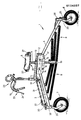
- the drawing shows an embodiment of an impeller according to the invention.
- 1 denotes an impeller which has a frame which consists of a frame bridge 2 to which a front rocker arm 3 and a rear rocker arm 4 are fastened in a vertically rotatable manner about horizontal axes 12, 14. Furthermore, a handlebar bracket 5 pointing forward is attached to the frame bridge 2 and a saddle 6.
- the two rockers 3 and 4 have at their bottom ends a front wheel 7 and a rear wheel 8 and are connected to one another by spring elements in the form of rubber tension springs 9.
- the rubber tensioning springs 9 do not, however, lead directly from the front rocker 3 to the rear rocker 4, but are essentially fixed in their central region on a height-adjustable adjusting tube 10.
- the adjusting 1o is mounted with a clamp-like clamping means adjustable in height on a seat tube 11, which in a guide tube 12 vertically adjustable within the frame bridge ge 2 - is leading.
- This independent height adjustment of both the saddle 6 and the rubber tension springs 9 ensures that the height of the saddle can be adjusted depending on the size of the user and that regardless of this size an adaptation to the different weights of the users can be achieved that the bias of the rubber tension springs 9 can be changed by a different height arrangement of the adjusting tube 1o. If, for example, the adjusting tube 10 is moved far upward, the rubber tensioning springs 9 are relieved of the condition shown in the drawing, so that the rubber tensioning springs 9 respond earlier and act softer, which is desirable for use by lighter persons.
- the upper steering lever 18 is connected to a handlebar 19 and rotates with it about a vertical axis.
- a lower steering lever 2 0 which is fixedly connected to the front wheel 7 rotatably mounted about a vertical axis, cooperates with the upper steering lever 18, since the two outer ends of each steering lever are connected in a variable length to the corresponding outer ends of the other steering lever.
- This variable-length connection consists of a chain 21, which has a tension spring 22 in the area of the lower steering lever 2o, so that the distance between the two steering levers is variable. Since the axle 14 and the upper steering lever 18 are essentially at the same height, the distance between the upper steering lever 18 and the lower steering lever 2o would correspond approximately to the length of the front rocker arm 3 if it were to point vertically downwards. If the front rocker arm 3 is aligned essentially horizontally, the distance between the upper steering lever 18 and the lower steering arm 20 is smaller by the amount than the length of the front rocker arm 3, which corresponds to the distance between the upper steering arm 18 and the axle 14 .
- the position of the front rocker 3 changes and thus also the distance between the upper steering lever and the lower steering lever 2 0 changes .
- the steering commands could also be transmitted, for example, by telescoping pipes or the like.
- a brake lever 24 for actuating a brake 25 acting on the rear wheel 8 by means of a Bowden cable is conveniently arranged for easy access.
- the saddle 6 has an elongated narrow shape and is formed by a leather-covered air-filled cushion, the hardness of which can be adjusted by means of different air pressure, the necessary valve means or the like are not shown.
- a frame structure 26 carrying the SatteL has, at its two longitudinal ends, releasable fastening means in the form of screws 27, with the aid of which the actual saddle 6 is fixed removably from the frame structure 26, so that it can be exchanged for another saddle with, for example, a different surface or other Interior element is made possible.
- the arrangement of the two wheels 7 and 8 at the bottom ends of the rockers 3 and 4 takes place via forks 29 rotatably mounted about vertical axes 28, which are designed such that the wheels 7 and 8 are arranged in a trailing manner, so that the wheels are stabilized independently done while running.
- the spring preload can be set so hard that the body weight to be borne by the patient himself is very low and this portion of the self-supporting weight can gradually be increased over time until the patient can walk completely safely again on his own.
- the wheel enables the natural course of movement to be maintained when running, in that it follows the up and down movement of the runner by deflecting the saddle height.
- the feet of the runner can be largely relieved of the burdening body weight, so that the covering of long distances or of high-speed distances for athletes or learning to walk for convalescent patients is made much easier by the impeller.
Landscapes
- Engineering & Computer Science (AREA)
- Mechanical Engineering (AREA)
- Handcart (AREA)
- Rehabilitation Tools (AREA)
- Automatic Cycles, And Cycles In General (AREA)
- Transplanting Machines (AREA)
Priority Applications (1)
| Application Number | Priority Date | Filing Date | Title |
|---|---|---|---|
| AT84109158T ATE34954T1 (de) | 1983-08-04 | 1984-08-02 | Laufrad. |
Applications Claiming Priority (2)
| Application Number | Priority Date | Filing Date | Title |
|---|---|---|---|
| DE3328103 | 1983-08-04 | ||
| DE3328103A DE3328103C2 (de) | 1983-08-04 | 1983-08-04 | Laufrad |
Publications (3)
| Publication Number | Publication Date |
|---|---|
| EP0134537A2 true EP0134537A2 (fr) | 1985-03-20 |
| EP0134537A3 EP0134537A3 (en) | 1986-03-05 |
| EP0134537B1 EP0134537B1 (fr) | 1988-06-08 |
Family
ID=6205721
Family Applications (1)
| Application Number | Title | Priority Date | Filing Date |
|---|---|---|---|
| EP84109158A Expired EP0134537B1 (fr) | 1983-08-04 | 1984-08-02 | Véhicule à roues actionnées au pied |
Country Status (3)
| Country | Link |
|---|---|
| EP (1) | EP0134537B1 (fr) |
| AT (1) | ATE34954T1 (fr) |
| DE (1) | DE3328103C2 (fr) |
Cited By (3)
| Publication number | Priority date | Publication date | Assignee | Title |
|---|---|---|---|---|
| EP1167171A1 (fr) * | 2000-06-30 | 2002-01-02 | Paul Ducourret | Véhicule roulant à propulsion pédestre |
| FR2821331A1 (fr) * | 2001-02-28 | 2002-08-30 | Marie France Lieutard | Dispositif destine au deplacement de personnes |
| KR101069503B1 (ko) | 2011-01-21 | 2011-09-30 | 이흥재 | 전륜과 후륜의 간격조절로 추진하는 자전거 |
Families Citing this family (9)
| Publication number | Priority date | Publication date | Assignee | Title |
|---|---|---|---|---|
| DE3704672A1 (de) * | 1987-02-14 | 1988-08-25 | Gertrud Fissl | Einrichtung als stand- bzw. gehhilfe fuer koerperlich behinderte personen |
| DE3720368A1 (de) * | 1987-06-19 | 1989-01-05 | Jens Ranke | Laufrad |
| DE3837185A1 (de) * | 1988-11-02 | 1990-05-03 | Herbert Ludwig | Faltbares und zerlegbares multifunktionales verwandlungs-sport- und freizeitgeraet zur muskel- oder motorisch angetriebenen rollenden und gleitenden fortbewegung auf der strasse, im gelaende, auf wasser, schnee und eis sowie als standgeraet fuer ruhenden gebrauch |
| DE29504467U1 (de) * | 1995-03-16 | 1996-07-18 | Hammer Sport Vertriebs-Gmbh, 89231 Neu-Ulm | Heimfahrrad für Trainingszwecke |
| DE29509586U1 (de) | 1995-06-12 | 1995-08-24 | Bauer, Ekkehard, 82266 Inning | Laufrad |
| DE10229698A1 (de) * | 2002-07-02 | 2004-01-29 | Martin Hoerdum | Faltrad |
| DE102004014500A1 (de) * | 2004-03-25 | 2005-10-13 | Oskar Seyschab | Sport- und Therapiegerät |
| RU2452649C1 (ru) * | 2011-02-17 | 2012-06-10 | Андрей Андреевич Захаров | Рама велосипеда |
| CN105109604B (zh) * | 2015-09-29 | 2017-11-03 | 太仓市车中宝休闲用品有限公司 | 绷紧布车座式三轮娱乐车 |
Family Cites Families (7)
| Publication number | Priority date | Publication date | Assignee | Title |
|---|---|---|---|---|
| DE649433C (de) * | 1937-08-24 | Paul Grunert | Gehrad | |
| GB191329499A (en) * | 1913-12-22 | 1914-02-05 | Hobbies Ltd | Improvements in Hobby-horses. |
| US1373814A (en) * | 1919-03-21 | 1921-04-05 | Edward J Hemington | Child's vehicle |
| FR545657A (fr) * | 1922-01-06 | 1922-10-18 | Cadre pour appareil de locomotion à deux roues | |
| US1668623A (en) * | 1925-05-05 | 1928-05-08 | Ralph C Avril | Coaster |
| CH176970A (de) * | 1934-08-15 | 1935-05-15 | Laarmann Otto | Reitroller. |
| DE7530321U (de) * | 1975-09-25 | 1976-03-18 | Schmitt, Karl, Dipl.-Ing., 6400 Fulda | Zweiradaehnliches spiel- und uebungsgeraet fuer kinder |
-
1983
- 1983-08-04 DE DE3328103A patent/DE3328103C2/de not_active Expired
-
1984
- 1984-08-02 EP EP84109158A patent/EP0134537B1/fr not_active Expired
- 1984-08-02 AT AT84109158T patent/ATE34954T1/de not_active IP Right Cessation
Cited By (4)
| Publication number | Priority date | Publication date | Assignee | Title |
|---|---|---|---|---|
| EP1167171A1 (fr) * | 2000-06-30 | 2002-01-02 | Paul Ducourret | Véhicule roulant à propulsion pédestre |
| FR2810959A1 (fr) * | 2000-06-30 | 2002-01-04 | Paul Ducourret | Vehicule roulant a propulsion pedestre |
| FR2821331A1 (fr) * | 2001-02-28 | 2002-08-30 | Marie France Lieutard | Dispositif destine au deplacement de personnes |
| KR101069503B1 (ko) | 2011-01-21 | 2011-09-30 | 이흥재 | 전륜과 후륜의 간격조절로 추진하는 자전거 |
Also Published As
| Publication number | Publication date |
|---|---|
| DE3328103A1 (de) | 1985-02-21 |
| EP0134537A3 (en) | 1986-03-05 |
| ATE34954T1 (de) | 1988-06-15 |
| DE3328103C2 (de) | 1987-01-29 |
| EP0134537B1 (fr) | 1988-06-08 |
Similar Documents
| Publication | Publication Date | Title |
|---|---|---|
| EP0960586B1 (fr) | Chaise, notamment chaise de bureau | |
| DE3309253C2 (fr) | ||
| EP0134537B1 (fr) | Véhicule à roues actionnées au pied | |
| DE2700402A1 (de) | Fahrzeug mit zur senkrechten schwenkbarem lotrechten rahmen (cambering vehicle) | |
| DE3508776C2 (de) | Stoßdämfpungseinrichtung zur Verwendung bei einem Fahrzeugsitz | |
| DE2725602A1 (de) | Stossabsorber fuer rollstuehle o.dgl. | |
| DE102008024745A1 (de) | Aufrichtrollstuhl | |
| DE2236253A1 (de) | Fahrzeugsitz | |
| DE3837018C2 (de) | Fahrrad mit verschiedenen Sitzpositionen | |
| DE3506026C2 (fr) | ||
| DE3232862C2 (fr) | ||
| DE19612632C2 (de) | Trainingsgerät | |
| DE9300997U1 (de) | Verstellbarer Sitz | |
| WO2002046032A1 (fr) | Vehicule repliable | |
| DE2922691A1 (de) | Dreirad | |
| DE9003931U1 (de) | Zusammenlegbares Farrad | |
| DE19637268B4 (de) | Kinderwagen | |
| DE3526264C2 (fr) | ||
| EP0628465B1 (fr) | Article de sport | |
| DE29512141U1 (de) | Gehhilfe | |
| DE3825124C2 (fr) | ||
| DE10019731A1 (de) | Kinder- oder Puppenwagengestell | |
| EP1059075A2 (fr) | Chaise mobile à roulettes | |
| DE3133381A1 (de) | Universell einbaubares zusatzgeraet zur handbetaetigung der fussbremse und der gaszufuhr von kraftfahrzeugen fuer beinbehinderte fahrer | |
| DE19844430C2 (de) | Fahrradrahmen |
Legal Events
| Date | Code | Title | Description |
|---|---|---|---|
| PUAI | Public reference made under article 153(3) epc to a published international application that has entered the european phase |
Free format text: ORIGINAL CODE: 0009012 |
|
| AK | Designated contracting states |
Designated state(s): AT BE CH FR GB IT LI NL |
|
| PUAL | Search report despatched |
Free format text: ORIGINAL CODE: 0009013 |
|
| AK | Designated contracting states |
Kind code of ref document: A3 Designated state(s): AT BE CH FR GB IT LI NL |
|
| 17P | Request for examination filed |
Effective date: 19860502 |
|
| 17Q | First examination report despatched |
Effective date: 19870818 |
|
| GRAA | (expected) grant |
Free format text: ORIGINAL CODE: 0009210 |
|
| AK | Designated contracting states |
Kind code of ref document: B1 Designated state(s): AT BE CH FR GB IT LI NL |
|
| PG25 | Lapsed in a contracting state [announced via postgrant information from national office to epo] |
Ref country code: NL Effective date: 19880608 Ref country code: IT Free format text: LAPSE BECAUSE OF FAILURE TO SUBMIT A TRANSLATION OF THE DESCRIPTION OR TO PAY THE FEE WITHIN THE PRESCRIBED TIME-LIMIT;WARNING: LAPSES OF ITALIAN PATENTS WITH EFFECTIVE DATE BEFORE 2007 MAY HAVE OCCURRED AT ANY TIME BEFORE 2007. THE CORRECT EFFECTIVE DATE MAY BE DIFFERENT FROM THE ONE RECORDED. Effective date: 19880608 Ref country code: FR Free format text: THE PATENT HAS BEEN ANNULLED BY A DECISION OF A NATIONAL AUTHORITY Effective date: 19880608 Ref country code: BE Effective date: 19880608 |
|
| REF | Corresponds to: |
Ref document number: 34954 Country of ref document: AT Date of ref document: 19880615 Kind code of ref document: T |
|
| GBT | Gb: translation of ep patent filed (gb section 77(6)(a)/1977) | ||
| PG25 | Lapsed in a contracting state [announced via postgrant information from national office to epo] |
Ref country code: AT Effective date: 19880802 |
|
| PG25 | Lapsed in a contracting state [announced via postgrant information from national office to epo] |
Ref country code: GB Free format text: LAPSE BECAUSE OF NON-PAYMENT OF DUE FEES Effective date: 19880808 |
|
| PG25 | Lapsed in a contracting state [announced via postgrant information from national office to epo] |
Ref country code: LI Effective date: 19880831 Ref country code: CH Effective date: 19880831 |
|
| EN | Fr: translation not filed | ||
| NLV1 | Nl: lapsed or annulled due to failure to fulfill the requirements of art. 29p and 29m of the patents act | ||
| PLBE | No opposition filed within time limit |
Free format text: ORIGINAL CODE: 0009261 |
|
| STAA | Information on the status of an ep patent application or granted ep patent |
Free format text: STATUS: NO OPPOSITION FILED WITHIN TIME LIMIT |
|
| REG | Reference to a national code |
Ref country code: CH Ref legal event code: PL |
|
| GBPC | Gb: european patent ceased through non-payment of renewal fee | ||
| 26N | No opposition filed |