EP0134565A2 - Contacteur avec un boîtier isolant en deux parties - Google Patents
Contacteur avec un boîtier isolant en deux parties Download PDFInfo
- Publication number
- EP0134565A2 EP0134565A2 EP84109816A EP84109816A EP0134565A2 EP 0134565 A2 EP0134565 A2 EP 0134565A2 EP 84109816 A EP84109816 A EP 84109816A EP 84109816 A EP84109816 A EP 84109816A EP 0134565 A2 EP0134565 A2 EP 0134565A2
- Authority
- EP
- European Patent Office
- Prior art keywords
- shell
- housing according
- shells
- double
- armature
- Prior art date
- Legal status (The legal status is an assumption and is not a legal conclusion. Google has not performed a legal analysis and makes no representation as to the accuracy of the status listed.)
- Ceased
Links
- 238000004804 winding Methods 0.000 claims description 4
- 239000011810 insulating material Substances 0.000 claims description 2
- 230000001681 protective effect Effects 0.000 claims description 2
- 238000010791 quenching Methods 0.000 claims description 2
- 230000000171 quenching effect Effects 0.000 claims description 2
- FYYHWMGAXLPEAU-UHFFFAOYSA-N Magnesium Chemical compound [Mg] FYYHWMGAXLPEAU-UHFFFAOYSA-N 0.000 claims 1
- 238000007664 blowing Methods 0.000 claims 1
- 229910052749 magnesium Inorganic materials 0.000 claims 1
- 239000011777 magnesium Substances 0.000 claims 1
- 230000000295 complement effect Effects 0.000 description 1
- 238000012423 maintenance Methods 0.000 description 1
- 230000007257 malfunction Effects 0.000 description 1
- 238000004519 manufacturing process Methods 0.000 description 1
Images


Classifications
-
- H—ELECTRICITY
- H01—ELECTRIC ELEMENTS
- H01H—ELECTRIC SWITCHES; RELAYS; SELECTORS; EMERGENCY PROTECTIVE DEVICES
- H01H50/00—Details of electromagnetic relays
- H01H50/02—Bases; Casings; Covers
Definitions
- the invention relates to a double-shell housing made of insulating material for single or double-pole contactors with double interruption, in which in the working position the contact pressure is applied by contact pressure springs acting on the contact bridges and the attracted armature tensions a return spring which is stronger than the contact pressure springs.
- the requirements of the housings of electrical contactors are generally that they enable the contactors to be manufactured easily and quickly and, in the event of a malfunction, that the cause be identified and rectified quickly and easily.
- the latter applies in particular when the contactors in devices such as. B. electrically powered trackless vehicles or electric vehicles are installed, in which regular maintenance by appropriately trained personnel is not always given or possible.
- the invention is therefore based on the object of specifying a housing for a contactor of the type described in the introduction, which allows easy and quick production, checking and repair of the contactor.
- the solution according to the invention is that the elements of the magnetic drive and the movable contacts and the return spring are accommodated in a first shell with corresponding recesses, while the fixed contacts and both shells are accommodated in a second shell are interconnected.
- the yoke is U-shaped and rests with its legs on the bottom of the first shell. It clamps the coil body with winding and core between its inner U-bottom and an eye formed on the bottom of the first shell, the length of which corresponds to the armature stroke.
- the yoke, the core and the eye are provided with aligned bores through which screw connections run, the armature is provided with a recess which is concentric with the bores mentioned and permits free play of the armature around the eye, and it has actuating tabs for holding the Contact bridge in the rest position.
- the return spring is prestressed against the shell by a holder passing through the first shell and a split pin fixing the holder on the outside of the shell.
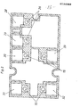
- FIGS. 1-10 show, in a partially schematic representation, an exemplary embodiment of a housing according to the teaching of the invention.
- the first shell of a housing is designated 1. It accommodates a two-pole contactor with double break, whose U-shaped yoke is labeled 2, and a single-pole contactor with double break, whose U-shaped yoke is labeled 3.
- the hatched area is not surmounted by any component shown in the shell 1 and is used for contact with the underside of the second shell, which is explained in an example with FIG. 2.
- the screw 9 passes through, as shown in FIG. 3, the yoke 2 and engages in the core 6 located in the coil former 5 '.
- the core 6 is braced against the bottom 7 of the shell by means of a further screw which is guided through the eye 8.
- the anchor 10 has 8 free play around the eye.
- the components are held under the yoke 4 by the screw 11.
- the armature 10 of the two-pole contactor carries the two actuating tabs 12.
- the actuating tab 12 keeps the cranked contact bridge 16 open against the contact pressure springs 14 under the action of the return spring in the idle state. Only when the magnetic drive is energized does the actuating tab 12 lift off, and the contact bridge 1C arrives at the fixed contacts assigned to it 15 under the action of the contact pressure springs 14 to the system.
- the fixed contacts 15 are, as shown in Fig. 2, attached to the inside of the second shell and provided on the outside with connection options.
- the fixed contacts 15 lie in the axis of the recesses 17 (FIG. 4) which receive the contact pressure springs 14 and approximately in the position shown in FIG. 4.
- the function of the return springs is explained with reference to FIGS. 1 and 5.
- the armature 10 carries two supports 18 for the return springs 19. In the position shown in FIG. 5, the armature 10 is shown in the working position, with the supports 18 tensioning the return springs 19 with respect to the guide body 20 and the cotter pin 21 against the housing 1 .
- the unipolar contactor behaves correspondingly, the armature of which has the actuating flap 22 and the supports 23 for the return spring 24.
- the contact bridge bears the designation 25 and works together with the fixed contacts 26 from FIG. 2.
- recesses for blow magnets are present in the first shell on both sides of the interruption points. These recesses are designated 27 in FIG. 1. Furthermore, there are further recesses in both shells, which complement one another to form arcing chambers in the case of interconnected shells. The associated recesses are provided with the numbers 28 to 33 in FIGS. 1 and 2, the recesses with the same numbers uniting to form an arc quenching chamber when the shells are assembled.
- openings are provided in the first shell, which can be closed by sliding panels that can be actuated from the outside. With them it is possible e.g. B. to observe the contact state.
- the two shells of the housing are detachably connected to one another by screws or clips.
- the housing according to the invention can be designed freely to accommodate one or more single or double pole contactors.
Landscapes
- Physics & Mathematics (AREA)
- Electromagnetism (AREA)
- Breakers (AREA)
- Switch Cases, Indication, And Locking (AREA)
- Electromagnets (AREA)
- Arc-Extinguishing Devices That Are Switches (AREA)
- Insulators (AREA)
Applications Claiming Priority (2)
| Application Number | Priority Date | Filing Date | Title |
|---|---|---|---|
| DE3330666 | 1983-08-25 | ||
| DE3330666 | 1983-08-25 |
Publications (2)
| Publication Number | Publication Date |
|---|---|
| EP0134565A2 true EP0134565A2 (fr) | 1985-03-20 |
| EP0134565A3 EP0134565A3 (fr) | 1987-08-05 |
Family
ID=6207417
Family Applications (1)
| Application Number | Title | Priority Date | Filing Date |
|---|---|---|---|
| EP84109816A Ceased EP0134565A3 (fr) | 1983-08-25 | 1984-08-17 | Contacteur avec un boítier isolant en deux parties |
Country Status (3)
| Country | Link |
|---|---|
| US (1) | US4621247A (fr) |
| EP (1) | EP0134565A3 (fr) |
| JP (1) | JPS60100327A (fr) |
Families Citing this family (1)
| Publication number | Priority date | Publication date | Assignee | Title |
|---|---|---|---|---|
| WO1990006609A1 (fr) * | 1988-11-16 | 1990-06-14 | Motorola, Inc. | Ensemble electronique avec substrat flexible |
Family Cites Families (8)
| Publication number | Priority date | Publication date | Assignee | Title |
|---|---|---|---|---|
| DD53159A (fr) * | ||||
| US3259702A (en) * | 1964-03-02 | 1966-07-05 | Allis Chalmers Mfg Co | Multiple contact switch with removable cover |
| DE1957794U (de) * | 1966-08-18 | 1967-03-30 | Siemens Ag | Flachrelais in miniaturbauweise. |
| GB1206969A (en) * | 1967-10-17 | 1970-09-30 | Ml Aviation Co Ltd | Electromagnetic relays |
| US3833869A (en) * | 1973-11-09 | 1974-09-03 | Amp Inc | Electromechanical relay |
| US4272746A (en) * | 1979-08-09 | 1981-06-09 | Guardian Electric Manufacturing Company | Four pole double throw relay |
| DE3146739C2 (de) * | 1981-11-25 | 1985-10-24 | Siemens AG, 1000 Berlin und 8000 München | Elektromagnetisches Schaltgerät |
| US4423399A (en) * | 1982-04-23 | 1983-12-27 | Essex Group, Inc. | Electromagnetic contactor |
-
1984
- 1984-08-17 EP EP84109816A patent/EP0134565A3/fr not_active Ceased
- 1984-08-21 US US06/642,944 patent/US4621247A/en not_active Expired - Fee Related
- 1984-08-24 JP JP59175317A patent/JPS60100327A/ja active Pending
Also Published As
| Publication number | Publication date |
|---|---|
| US4621247A (en) | 1986-11-04 |
| EP0134565A3 (fr) | 1987-08-05 |
| JPS60100327A (ja) | 1985-06-04 |
Similar Documents
| Publication | Publication Date | Title |
|---|---|---|
| DE3874168T2 (de) | Fernbetaetigter ein-/aus-schutzschalter. | |
| DE3843359C2 (fr) | ||
| DE1267309B (de) | Elektrisches Schuetz, bei dem Kontaktbruecke und Festkontakte als Baueinheit ausgebildet sind | |
| DE19939020B4 (de) | Elektromagnetisches Schaltschütz | |
| DE3713537A1 (de) | Umkehr-schaltvorrichtung mit ueberstromschutz | |
| DE2632901A1 (de) | Motoranlasser | |
| DE2149365A1 (de) | Schalter in Baukastenweise | |
| EP0022953B2 (fr) | Relais électromagnétique | |
| EP0829092A1 (fr) | Commutateur electromagnetique | |
| EP0114231A1 (fr) | Dispositif de protection contre la surintensité | |
| DE3211685A1 (de) | Schuetze zur steuerung von elektromotoren | |
| EP0134565A2 (fr) | Contacteur avec un boîtier isolant en deux parties | |
| EP0000711A1 (fr) | Contacteur avec bornes de raccordement librement accessibles et disposées dans des plans différents | |
| DE60130143T2 (de) | Strombegrenzender schutzschalter | |
| DE1909460A1 (de) | Magnetisches Steuerrelais | |
| DE102013214209A1 (de) | Elektrischer Schaltkontakt und Schaltvorrichtung mit selbigem | |
| DE1614837B2 (de) | Elektromagnetisches schuetz | |
| DE1113500B (de) | Elektrisches Schaltgeraet | |
| DE877165C (de) | Aus Sockel und Oberteil bestehender Schutzschalter | |
| DE2433536A1 (de) | Klappankerrelais oder -schuetz | |
| EP1148021B1 (fr) | Contact pour porte | |
| WO1981003578A1 (fr) | Relais pour courants eleves | |
| DE1261224B (de) | Elektromagnetisches, mit Kontaktbruecken ausgestattetes Schaltgeraet, insbesondere Schuetz | |
| DE2314597A1 (de) | Reversierschuetz | |
| DE2805424A1 (de) | Schuetz mit magnetantrieb zum wahlweisen betrieb als oeffner- oder schliesserschuetz |
Legal Events
| Date | Code | Title | Description |
|---|---|---|---|
| PUAI | Public reference made under article 153(3) epc to a published international application that has entered the european phase |
Free format text: ORIGINAL CODE: 0009012 |
|
| AK | Designated contracting states |
Designated state(s): DE FR GB IT SE |
|
| ITCL | It: translation for ep claims filed |
Representative=s name: BARZANO' E ZANARDO ROMA S.P.A. |
|
| EL | Fr: translation of claims filed | ||
| PUAL | Search report despatched |
Free format text: ORIGINAL CODE: 0009013 |
|
| AK | Designated contracting states |
Kind code of ref document: A3 Designated state(s): DE FR GB IT SE |
|
| 17P | Request for examination filed |
Effective date: 19870721 |
|
| 17Q | First examination report despatched |
Effective date: 19890405 |
|
| STAA | Information on the status of an ep patent application or granted ep patent |
Free format text: STATUS: THE APPLICATION HAS BEEN REFUSED |
|
| 18R | Application refused |
Effective date: 19900128 |
|
| RIN1 | Information on inventor provided before grant (corrected) |
Inventor name: HAPPACH, ANTON |