EP0134701B1 - Gradientenfelder mit Offset-Kompensation für mit magnetischer Kernresonanz arbeitende Bilderzeugungssysteme - Google Patents
Gradientenfelder mit Offset-Kompensation für mit magnetischer Kernresonanz arbeitende Bilderzeugungssysteme Download PDFInfo
- Publication number
- EP0134701B1 EP0134701B1 EP84305284A EP84305284A EP0134701B1 EP 0134701 B1 EP0134701 B1 EP 0134701B1 EP 84305284 A EP84305284 A EP 84305284A EP 84305284 A EP84305284 A EP 84305284A EP 0134701 B1 EP0134701 B1 EP 0134701B1
- Authority
- EP
- European Patent Office
- Prior art keywords
- magnetic field
- gradient
- field
- region
- resonance imaging
- Prior art date
- Legal status (The legal status is an assumption and is not a legal conclusion. Google has not performed a legal analysis and makes no representation as to the accuracy of the status listed.)
- Expired
Links
- 238000013421 nuclear magnetic resonance imaging Methods 0.000 title claims description 21
- 239000002131 composite material Substances 0.000 claims description 7
- 230000001747 exhibiting effect Effects 0.000 claims description 3
- 238000009826 distribution Methods 0.000 claims description 2
- 230000003068 static effect Effects 0.000 abstract description 20
- 238000003384 imaging method Methods 0.000 abstract description 13
- 238000005481 NMR spectroscopy Methods 0.000 description 13
- 239000013598 vector Substances 0.000 description 11
- 239000000463 material Substances 0.000 description 9
- 238000004804 winding Methods 0.000 description 9
- 238000000034 method Methods 0.000 description 6
- 238000006073 displacement reaction Methods 0.000 description 5
- 230000000694 effects Effects 0.000 description 5
- 230000035945 sensitivity Effects 0.000 description 5
- 230000000295 complement effect Effects 0.000 description 4
- 230000008901 benefit Effects 0.000 description 2
- 230000015572 biosynthetic process Effects 0.000 description 2
- 230000005415 magnetization Effects 0.000 description 2
- 238000009987 spinning Methods 0.000 description 2
- 230000002411 adverse Effects 0.000 description 1
- 230000007423 decrease Effects 0.000 description 1
- 238000001514 detection method Methods 0.000 description 1
- 230000005669 field effect Effects 0.000 description 1
- 229910052739 hydrogen Inorganic materials 0.000 description 1
- 239000001257 hydrogen Substances 0.000 description 1
- 125000004435 hydrogen atom Chemical class [H]* 0.000 description 1
- 238000004519 manufacturing process Methods 0.000 description 1
Images


Classifications
-
- G—PHYSICS
- G01—MEASURING; TESTING
- G01R—MEASURING ELECTRIC VARIABLES; MEASURING MAGNETIC VARIABLES
- G01R33/00—Arrangements or instruments for measuring magnetic variables
- G01R33/20—Arrangements or instruments for measuring magnetic variables involving magnetic resonance
- G01R33/28—Details of apparatus provided for in groups G01R33/44 - G01R33/64
- G01R33/38—Systems for generation, homogenisation or stabilisation of the main or gradient magnetic field
- G01R33/385—Systems for generation, homogenisation or stabilisation of the main or gradient magnetic field using gradient magnetic field coils
-
- G—PHYSICS
- G01—MEASURING; TESTING
- G01R—MEASURING ELECTRIC VARIABLES; MEASURING MAGNETIC VARIABLES
- G01R33/00—Arrangements or instruments for measuring magnetic variables
- G01R33/20—Arrangements or instruments for measuring magnetic variables involving magnetic resonance
- G01R33/28—Details of apparatus provided for in groups G01R33/44 - G01R33/64
- G01R33/38—Systems for generation, homogenisation or stabilisation of the main or gradient magnetic field
- G01R33/381—Systems for generation, homogenisation or stabilisation of the main or gradient magnetic field using electromagnets
Definitions
- This invention relates to gradient fields in nuclear magnetic resonance (NMR) imaging systems and, in particular, to techniques for offsetting gradient fields from their nominal origins in the system.
- NMR nuclear magnetic resonance
- the principles of NMR may be employed to form images of various materials.
- the material to be imaged is placed in a uniform static magnetic field, which causes the spin vectors of atomic nuclei to become aligned in the direction of the magnetic field vector.
- the spin vectors are then disturbed from their equilibrium alignment in a controlled manner by energy produced by a radio frequency (r.f.) coil, which reorients the spin vectors to a new alignment.
- r.f. radio frequency
- the emitted signals comprise the total contribution of many individual signals and the total signal may therefore be termed a bulk magnetization signal.
- the bulk magnetization signal is detected by an r.f. receiving coil and may thereafter be processed to produce an image of the material in terms of the characteristics of the content of its atomic nuclei.
- the nuclear signals In order to form a planar image of the material it is necessary to be able to positionally identify the source or sources of the NMR signal. For the formation of a two dimensional image having x and y coordinates for instance, the nuclear signals must be encoded so that they will exhibit characteristics upon reception which identify their sources positionally in both the x and y directions.
- This encoding is conventionally performed by imposing gradient fields upon the static magnetic field.
- the gradient fields are developed by gradient coils, and may perform positional encoding by either phase encoding or frequency encoding.
- phase encoding the nuclei are subjected to a momentary gradient field before the nuclear signals are acquired, or "read".
- the momentary gradient field during its application exhibits a magnitude which varies linearly with position in a desired direction in the region of the imaged material, and acts to momentarily shift the frequencies of the spin vectors as a function of position.
- the spin vectors of nuclei in the material return to their initial Larmor frequency, but as a result of the momentary frequency shift, they are now preencoded in phase.
- signals emitted from different positions in the direction of the gradient will exhibit different relative phases. Through signal phase detection, the location of the sources of the signals in the direction of the gradient may be determined.
- the gradient field is applied during the time of signal acquisition, when the nuclear signals are read.
- this gradient field exhibits a magnitude which varies linearly with position along the desired direction of the gradient.
- the Larmor frequency of a spinning nucleus is a function of the magnitude of the magnetic field applied to it, nuclei at different positions along the gradient direction will exhibit different Larmor frequencies which are a function of the positionally varying gradient field.
- the frequencies of the acquired nuclear signals will identify the position of the nuclei along the gradient direction.
- phase encoding may be used to positionally identify the y coordinate of a spinning nucleus
- frequency encoding may be used to positionally identify its x coordinate, for instance.
- the gradient coils used in an NMR system for imaging the human body are generally wound around a cylindrical coil form.
- the gradient fields are developed within the cylinder, where the patient being imaged is located.
- the gradient coils are usually wound in a symmetrical fashion with respect to the center axis of the cylinder, thereby producing gradient fields which are symmetrical with respect to the center axis of the cylinder.
- the cylinder and coils are conventionally oriented so that the cylinder center axis is aligned with the static magnetic field B o .
- the center axis may then be taken as the z axis of the system, with x and y axes oriented normal to the center axis and to each other.
- the gradient fields exhibit essentially no effect at the center point.
- the center point is then a null point for the gradients, as they have zero values at this point.
- frequency encoding will result in signals from material at the null point exhibiting the nominal Larmor frequency for the static B o field.
- Signals originating from material on either side of the null point will exhibit frequencies above and below this nominal frequency.
- the received signals may then be passed through a bandpass filter centered at the nominal frequency for an improved signal-to-noise ratio, and the symmetry of frequencies will lend itself to array processing and Fourier transform reconstruction.
- the passband of the bandpass filter must then be changed to the frequencies resulting from the gradient fields in the region of interest, or the same filter must have an undesirably broad passband to accommodate a broader frequency range, which adversely affects the signal-to-noise ratio.
- a nuclear magnetic resonance imaging system comprising:
- EP-A-0 108 421 which designates the states DE, FR, GB and NL is prior art in respect of these states by virtue of Article 54(3) and (4) EPC.
- the Toshiba application discloses a nuclear magnetic resonance imaging system having a magnet for producing a main magnetic field, four saddle shaped coils for producing gradients in the x direction, four saddle shaped coils for producing gradients in the y direction, two cylindrical coils for producing gradients in the z direction, two saddle shaped coils for producing a field offset in the x direction, two saddle shaped coils for producing a field offset in the y direction, and a cylindrical coil for producing a field offset in the z direction.
- the Toshiba system requires a total of fifteen coils for controlling the strength and location of the gradients in the static magnetic field.
- a nuclear magnetic resonance imaging system comprising:
- the present invention also provides, for all designated states, a nuclear magnetic resonance imaging system comprising:
- the present invention also provides, for all designated states, a nuclear magnetic resonance imaging system comprising:
- FIG. 1 a body of material 10 which is to be imaged in an NMR system is illustrated. Within the body 10 are three smaller rectangular blades A, B, and C. Block B is separately identified by its shaded sides.
- the NMR system has three reference axes, x, y and z. The reference axes all intersect at a common point 12 in the center of block B.
- the static magnetic field B o is oriented in the direction of the z axis.
- the center point 12 is also taken to be the center of gradient fields of the system.
- G x and Gy are shown in an enlarged view of blocks B and C of Figure 1.
- the G x gradient is applied to the static field B o , with a field strength variation in the x direction.
- the Gy gradient is also a variation of the static field B o , but the variation is in the y direction.
- the field variation of each gradient proceeds linearly in opposite senses from the common intersection point 12, a null point. At the null point, the gradients make no contribution to the net magnetic field, which remains at the value of the static field B o .
- null point 12 is a point of reference for all three gradients, including a z directional gradient G z which is not illustrated in Figures 1 and 2, the null point is designated as having coordinates X o , Y o , Z o .
- the illustrated gradients are seen to be symmetrically distributed with respect to block B. This distribution lends itself well to imaging block B using a narrow range of frequencies for spatial identity, which will be discussed more fully with respect to Figurs 3a and 3b. However, these conditions of symmetry do not apply to block C.
- the center 14 of block C is on the null plane of the z gradient along the z direction, which is the plane where the z gradient exhibits a magnitude contribution of zero, at z o .
- the center 14 of block C is also on the null plane of the Gy gradient, where that gradient makes a zero magnitude contribution to the static B o field.
- the center 14 is not on the null plane of the G x gradient; it is at a point where the G x gradient has a magnitude X n .
- the center 14 of block C may thus be designated as having coordinates X n , Y o , Z o . It would be desirable when imaging block C for the common null point of the three gradients to be shifted, or offset to the x n , y o , z o coordinate.
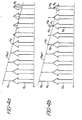
- the x-directed gradient G x of Figure 2 is shown in the plane of the drawing, as if the x axis of Figure 2 were viewed from the top of blocks B and C.
- the G x vector arrows are shown distributed in opposing polarity variation about the x o , y o , z o coordinate, and are bounded by lines representing opposite polarity driving currents I + and I_ of an x gradient coil.
- resonant nuclei will emit signals at their Larmor frequencies, which frequencies are equal to the strength of the magnetic field multiplied by the gyromagnetic ratio, which is unique for each nuclear species of nonzero spin.
- nuclei at the x o , y o , z o null point of the G x gradient field will emit signals which are a product of the strength of the static magnetic field B o , since the G x gradient makes no contribution to the static field at that point.
- the G x gradient field adds to and decreases the magnetic field strength on either side of the null point in Figure 3a, so that nuclei at those points will exhibit slightly higher and lower Larmor frequencies.
- This range of frequencies is indicated by the frequency range f min to f max shown below the x axis.
- the f min to f max frequency range indicates x- coordinate locations for nuclei in block B.
- Block C is located in a different G x gradient field, with the center of the block at coordinates x n , y o , z o .
- the vector arrows of the G x field are increasingly negative-going along the x-axis of the block, thereby causing nuclei in block C to exhibit Larmor frequencies outside the f min to f max frequency range.
- signals from only block C may be acquired by offsetting the G x gradient field from its nominal position so that the null point of the offset field is located at point X n , Y o , Z o .
- This effect is shown in Figure 3b, with the offset G x gradient vector arrows bounded by driving currents I + +I B+ and I_+I B _.
- the offset G x gradient field results in the f min to f max frequency range being symmetrically distributed on either side of the new gradient field null point, X n , Y o , Z a .
- NMR signals may now be received from block C with the same passband circuitry used to receive signals from the f min to f max frequency range of Figure 3a.
- signals from block B now exhibit frequencies above the f min to f max frequency range.
- FIGs 4a and 4b show the importance of the net magnetic field at any imaging point.
- the large arrows represent the static magnetic field component B o existing at every point along the X axis. But at every point, the net field is the combination of the static B o field and a smaller gradient field component, B a .
- the net field in the X direction is the linearly varying combination of the B o and B G field components, as shown by line B NET , which connects the arrowheads of the B G components.
- line B NET which connects the arrowheads of the B G components.
- the null point X o where the gradient field makes no contribution to the static B o field component.
- the B G components add to the B o field, and to the right of point X o the B G components reduce the net field to levels less than the B o component.
- a bias field component B B is added to the other two field component shown in Figure 4a.
- the bias field component B B uniformly offsets the previous net field B NET .
- the net field is thus determined by vectorially adding B o , B G and B B at each point.
- the result of this vectorial combination is that the B B and B G components cancel each other at point X n , which is now the null point of the bias and gradient fields together.
- Only the static field component B o remains at point X n .
- the net field is now the sum of the B o and B B components. It is therefore seen that the net field B NET of Figure 4b is offset to the right as compared to the B NET field of Figure 4a.
- the bias field is developed by a separate bias coil.
- the gradient coil arrangement of the system thus comprises four coils: a G x gradient coil, a Gy gradient coil, a G z gradient coil, and the bias coil.
- the bias coil may take any shape, so long as the field produced results in an essentially uniform offset in the main field. It is also desirable that there be some sort of linear relationship between the field modulation produced by the bias coil and the field effect of the gradient coils, thereby permitting simultaneous operation of the bias and gradient coils with predictable results.
- the bias coil produces an effective magnetic field component at the geometric null point of the gradient fields.
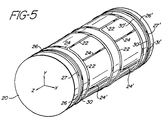
- the bias and gradient coils of the preferred embodiment are shown schematically in Figure 5.
- the coils there shown are formed around a cylindrical coil form 20.
- the X, Y and Z coordinate axes are shown at one end of the coil form 20.
- On the visible side of the coil form cylinder 20 are a pair of G x gradient coils 22.
- the arrows on the coils indicate current direction. These two coils comprise half of. Golay coil configuration.
- a complementary pair of G x gradient coils are located on the back of the cylinder, and are not visible in Figure 5.
- On the top of the coil form 20 is a pair of Gy gradient coils 24, also wound in a Golay coil configuration.
- a complementary pair of Gy gradient coils 24' is partially visible at the bottom of the coil form.
- the coil form cylinder At the ends of the coil form cylinder are two loops 26 and 26' of a G z gradient coil.
- the current direction in loop 26 is clockwise, as indicated by arrow 27, and the current direction in loop 26' is counterclockwise, as indicated by arrow 27'.
- the coils 26 and 26' thus form a reverse Helmholz configuration.
- loops 30 and 30' are also located at the ends of the coil form 20 .
- the current in loops 30 and 30' flows in the same direction about the coil form, as indicated by arrows 31 and 31'. Loops 30 and 30' thus form a Helmholz coil configuration.
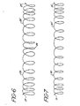
- the actual winding forms of the G z coil 26, 26' and the bias coil 30, 30' are comparatively shown in Figures 6 and 7.
- the G z gradient coil is shown as a continuous winding along the coil form, with coil turns more closely spaced at the ends than in the middle of the cylinder. At the mid-point of the cylinder the winding direction reverses as shown at 28, which provides the reversal in current direction with respect to the cylinder indicated by arrows 27 and 27'.
- the bias coil winding 30, 30' is shown in Figure 7, also in the form of a spiral, with windings more closely spaced at the ends of the cylindrical coil form.
- the bias coil unlike the G z gradient coil, does not reverse direction in the middle so that current flows in one direction as indicated by arrows 31, 31'.
- the bias coil may take any form so long as a uniform field offset is produced.
- the spiral winding pattern of Figure 7 has been found to be advantageous because it produces a more uniform field than the standard Helmholz configuration.
- the bias coil is energized or pulsed in synchronization with the gradient coils. If no field offset is desired, as in the case of imaging block B in the above example, the bias coil is not energized.
- the bias coil may also be used to correct undesired offsets of the usual gradient fields. For instance, if the null point of the Gy gradient field is not precisely aligned with the null points of the G x and Gy gradient fields during imaging of block B, the bias coil may be energized to move the effective null point of the Gy gradient field back into alignment with the null points of the other two gradient fields. If the NMR uses a relatively low level static field, as in the case of a low power resistive magnet, for instance, the bias coil may even be used to compensate for small main field drifts.
- the bias coil may be used to effect an offset in any direction, its drive current must be computed vectorially to control the magnitude and direction of the bias field.
- the three gradient coils produce a variation of the Z component of the static magnetic field in the Z direction as per the following relationships: where B nz is the Z field component due to a field gradient in the n direction, k n is the sensitivity factor of coil n to current, x, y and z are displacements from the center of the coil system in the x, y and z directions respectively, and i n is the current in the gradient coil for the n direction.
- the z component of the gradient field may be described by: where X o , Y o , and Z o are the coordinates of the null point of the coil configuration.
- X o , Y o , and Z o are the coordinates of the null point of the coil configuration.
- the bias coil produces a uniform field component in the z direction, and its field may be expressed in the same manner as:
- the displacement of the null point X o , Y o , Z o to a new null point X n , Y n , Z n is accomplished by making the current i B in the bias coil a linear combination of the currents in the three gradient coils according to the following relationship
- equations [2] and [3] into the gradient field expression of equation [1]
- the net field with the bias field component is: which simplifies to which is seen to be the desired offset gradient field with its null point at (X n , Y n , Z n ).
- FIG. 8 schematically illustrates a pair of reverse Helmholz gradient coils for the z direction, wound around a coil form 20.
- the first pair of coils 41 and 42 are energized with oppositely flowing currents as indicated by arrows I 41 and 1 42 .
- This pair of coils when energized by currents of equal magnitude, exhibits a field null point n 12 located midway between the two loops.
- coils 43 and 44 are energized with currents flowing as indicated by arrows 1 43 and I 44 .
- Coils 43 and 44 when equally energized, exhibit a field null point n 34 located midway between those two loops.
- coil 41 is connected to coil 42
- coil 43 is connected to coil 44, so that 1 4 , equals 1 42 and 1 43 equals I 44 , with current directions as indicated in Figure 8.
- the currents of the coil pairs can be modulated in complementary fashion to achieve the desired z gradient null point within the range of n 12 to n 34 . It is to be noted that this coil arrangement obviates the need for any further z gradient coils for the range of n 12 to n 34 .
- FIGS 9a and 9b illustrate Golay coil configurations, in which the current directions are indicated by arrows on the loops nearest the viewer. For ease of illustration, the coil form is removed.
- FIG 9a loops 51 are nearest the viewer, and oppose smaller loops 51', which are in back. Since the opposing loops are asymmetric, the field null point will not be at the center C, but to the left of center as indicated at n.
- Figure 9b the smaller loops 53 are in front, and larger loops 53' are in back. The loops 53, 53' will exhibit a field null point n to the right of center C.
- the coils of Figures 9a and 9b would overlay each other on the same coil form.
- the null point n is located as indicated in Figure 9a.
- the null point n is located as shown in Figure 9b.
- Complementary control of currents in the loops can move the null to any point between the indicated n points.
- Equal magnitude energization assuming equal coil sensitivity, will locate the null point at the center C.
- four coil amplifiers are necessary: one for coils 51, one for coils 51', one for coils 53, and one for coils 53'.
- the current in opposing coils 51-51' and 53-53' in the two Figures will not be the same. Hence, care is required in the exact proportioning of the relative coil currents.
- a further technique for developing the gradient null point offset is to form a bias coil from two G z coils, such as those shown in Figure 6, with their respective null points offset from each other, as in Figure 8.
Landscapes
- Physics & Mathematics (AREA)
- Condensed Matter Physics & Semiconductors (AREA)
- General Physics & Mathematics (AREA)
- Magnetic Resonance Imaging Apparatus (AREA)
- Particle Accelerators (AREA)
Claims (20)
Priority Applications (1)
| Application Number | Priority Date | Filing Date | Title |
|---|---|---|---|
| AT84305284T ATE47912T1 (de) | 1983-08-05 | 1984-08-03 | Gradientenfelder mit offset-kompensation fuer mit magnetischer kernresonanz arbeitende bilderzeugungssysteme. |
Applications Claiming Priority (2)
| Application Number | Priority Date | Filing Date | Title |
|---|---|---|---|
| GB8321236 | 1983-08-05 | ||
| GB838321236A GB8321236D0 (en) | 1983-08-05 | 1983-08-05 | Gradient null displacement coil |
Publications (3)
| Publication Number | Publication Date |
|---|---|
| EP0134701A2 EP0134701A2 (de) | 1985-03-20 |
| EP0134701A3 EP0134701A3 (en) | 1986-02-05 |
| EP0134701B1 true EP0134701B1 (de) | 1989-11-08 |
Family
ID=10546923
Family Applications (1)
| Application Number | Title | Priority Date | Filing Date |
|---|---|---|---|
| EP84305284A Expired EP0134701B1 (de) | 1983-08-05 | 1984-08-03 | Gradientenfelder mit Offset-Kompensation für mit magnetischer Kernresonanz arbeitende Bilderzeugungssysteme |
Country Status (5)
| Country | Link |
|---|---|
| US (1) | US4636728A (de) |
| EP (1) | EP0134701B1 (de) |
| AT (1) | ATE47912T1 (de) |
| DE (1) | DE3480427D1 (de) |
| GB (1) | GB8321236D0 (de) |
Families Citing this family (16)
| Publication number | Priority date | Publication date | Assignee | Title |
|---|---|---|---|---|
| JPS5985651A (ja) * | 1982-11-08 | 1984-05-17 | 株式会社東芝 | 診断用核磁気共鳴装置 |
| US4617516A (en) * | 1983-09-06 | 1986-10-14 | General Electric Company | Axial magnetic field gradient coil suitable for use with NMR apparatus |
| GB8500248D0 (en) * | 1985-01-04 | 1985-02-13 | Oxford Magnet Tech | Solenoids |
| US4673880A (en) | 1985-08-16 | 1987-06-16 | Technicare Corporation | Phase sensitive detection in multislice magnetic resonance imaging systems |
| US4733189A (en) * | 1986-06-03 | 1988-03-22 | Massachusetts Institute Of Technology | Magnetic resonance imaging systems |
| NL8603076A (nl) * | 1986-12-03 | 1988-07-01 | Philips Nv | Gradient spoel voor magnetisch kernspin apparaat. |
| FR2612641B1 (fr) * | 1987-03-19 | 1989-06-09 | Oreal | Appareil pour l'examen d'un corps par resonance magnetique nucleaire par des methodes lentes et rapides, notamment pour l'examen de la couche superficielle de ce corps, dispositif pour creer un gradient de champ magnetique pour un tel appareil, et application a l'imagerie de la peau du corps humain |
| US4920316A (en) * | 1989-03-30 | 1990-04-24 | Siemens Medical Systems, Inc. | Method and apparatus for reducing base field shifts in a magnetic resonance device due to pulsed magnetic field gradients |
| NL9002574A (nl) * | 1990-11-27 | 1992-06-16 | Philips Nv | Magnetisch resonantieapparaat. |
| GB9105286D0 (en) * | 1991-03-13 | 1991-04-24 | Oxford Instr Ltd | Magnetic field generating apparatus |
| US5379767A (en) * | 1992-09-02 | 1995-01-10 | The Regents Of The University Of California | MRI RF coil using zero-pitch solenoidal winding |
| US5311135A (en) * | 1992-12-11 | 1994-05-10 | General Electric Company | Multiple tap gradient field coil for magnetic resonance imaging |
| JP3283242B2 (ja) * | 1999-06-21 | 2002-05-20 | ジーイー横河メディカルシステム株式会社 | 勾配コイルの製造方法、勾配コイルおよびmri装置 |
| US6924644B2 (en) * | 2003-09-12 | 2005-08-02 | The United States Of America As Represented By The Secretary Of The Navy | Radiofrequency surface detection coil |
| US7250762B2 (en) * | 2005-07-07 | 2007-07-31 | General Electric Company | Method and system of MR imaging with reduced FSE cusp artifacts |
| US11487039B2 (en) | 2017-10-16 | 2022-11-01 | Halliburton Energy Services, Inc. | Multi-coil tool for attenuation of motion-induced noise during remote field testing of pipe |
Family Cites Families (9)
| Publication number | Priority date | Publication date | Assignee | Title |
|---|---|---|---|---|
| US4015196A (en) * | 1974-04-05 | 1977-03-29 | National Research Development Corporation | Analysis of materials |
| GB1578910A (en) * | 1978-05-25 | 1980-11-12 | Emi Ltd | Imaging systems |
| US4297637A (en) * | 1978-07-20 | 1981-10-27 | The Regents Of The University Of California | Method and apparatus for mapping lines of nuclear density within an object using nuclear magnetic resonance |
| JPS574541A (en) * | 1980-06-12 | 1982-01-11 | Toshiba Corp | Nuclear magnetic resonance apparatus |
| US4458203A (en) * | 1980-12-11 | 1984-07-03 | Picker International Limited | Nuclear magnetic resonance imaging |
| US4475084A (en) * | 1981-01-15 | 1984-10-02 | Picker International Limited | Nuclear magnetic resonance detector |
| DE3133873A1 (de) * | 1981-08-27 | 1983-03-17 | Siemens AG, 1000 Berlin und 8000 München | Gradientenspulen-system fuer eine einrichtung der kernspinresonanz-technik |
| US4594550A (en) * | 1982-09-07 | 1986-06-10 | Utsunomiya University | Method of scanning specifying magnetic field for nuclear magnetic resonance imaging |
| JPS5985651A (ja) * | 1982-11-08 | 1984-05-17 | 株式会社東芝 | 診断用核磁気共鳴装置 |
-
1983
- 1983-08-05 GB GB838321236A patent/GB8321236D0/en active Pending
-
1984
- 1984-06-18 US US06/621,396 patent/US4636728A/en not_active Expired - Fee Related
- 1984-08-03 EP EP84305284A patent/EP0134701B1/de not_active Expired
- 1984-08-03 DE DE8484305284T patent/DE3480427D1/de not_active Expired
- 1984-08-03 AT AT84305284T patent/ATE47912T1/de not_active IP Right Cessation
Also Published As
| Publication number | Publication date |
|---|---|
| EP0134701A3 (en) | 1986-02-05 |
| ATE47912T1 (de) | 1989-11-15 |
| EP0134701A2 (de) | 1985-03-20 |
| US4636728A (en) | 1987-01-13 |
| DE3480427D1 (en) | 1989-12-14 |
| GB8321236D0 (en) | 1983-09-07 |
Similar Documents
| Publication | Publication Date | Title |
|---|---|---|
| EP0134701B1 (de) | Gradientenfelder mit Offset-Kompensation für mit magnetischer Kernresonanz arbeitende Bilderzeugungssysteme | |
| US6043658A (en) | MR apparatus including an MR coil system | |
| EP0084946B1 (de) | Generator- oder Detektorapparat für Feldkomponenten in einem magnetischen Resonanz-System | |
| EP0231879B1 (de) | Selbstgeschmirmte Gradientspulen für Abbildung in kernmagnetischer Resonanz | |
| US5471140A (en) | Magnetic field generating assembly | |
| US5166619A (en) | Gradient coil assembly for a magnetic resonance imaging apparatus | |
| NL1026270C2 (nl) | Werkwijze en systeem voor versnelde beeldvorming onder gebruikmaking van parallelle MRI. | |
| US4739266A (en) | MR tomography method and apparatus for performing the method | |
| US4926125A (en) | Surface gradient assembly for high speed nuclear magnetic resonance imaging | |
| US4728895A (en) | System of coils for producing additional fields for obtaining polarization fields with constant gradients in a magnet having polarization pole pieces for image production by nuclear magnetic resonance | |
| US4862086A (en) | System for generating magnetic fields utilized for magnetic resonance imaging apparatus | |
| US4594550A (en) | Method of scanning specifying magnetic field for nuclear magnetic resonance imaging | |
| US4972148A (en) | Magnetic resonance tomography method and magnetic resonance tomography apparatus for performing the method | |
| US4833410A (en) | System of coils for producing magnetic field gradients of very uniform polarization in an imaging or spectroscopy installation by NMR | |
| US5739687A (en) | Magnetic field generating assembly | |
| US4644277A (en) | NMR tomography apparatus | |
| US6768303B1 (en) | Double-counter-rotational coil | |
| JP3705996B2 (ja) | 磁気共鳴撮影装置 | |
| CA2329006A1 (en) | Magnetic gradient field projection | |
| US4878021A (en) | Magnetic resonance spectroscopy studies of restricted volumes | |
| US5089784A (en) | Method for restricting region for magnetic resonance imaging | |
| US4767993A (en) | Coil system for magnetic resonance imaging | |
| JPH01207044A (ja) | 核磁気共鳴画像診断装置の受信装置 | |
| US5300887A (en) | Pulsed field MRI system with spatial selection | |
| US4804919A (en) | Nuclear magnetic resonance imaging method and apparatus for realizing same |
Legal Events
| Date | Code | Title | Description |
|---|---|---|---|
| PUAI | Public reference made under article 153(3) epc to a published international application that has entered the european phase |
Free format text: ORIGINAL CODE: 0009012 |
|
| AK | Designated contracting states |
Designated state(s): AT BE CH DE FR GB IT LI LU NL SE |
|
| PUAL | Search report despatched |
Free format text: ORIGINAL CODE: 0009013 |
|
| AK | Designated contracting states |
Designated state(s): AT BE CH DE FR GB IT LI LU NL SE |
|
| 17P | Request for examination filed |
Effective date: 19860711 |
|
| 17Q | First examination report despatched |
Effective date: 19871208 |
|
| ITF | It: translation for a ep patent filed | ||
| GRAA | (expected) grant |
Free format text: ORIGINAL CODE: 0009210 |
|
| AK | Designated contracting states |
Kind code of ref document: B1 Designated state(s): AT BE CH DE FR GB IT LI LU NL SE |
|
| PG25 | Lapsed in a contracting state [announced via postgrant information from national office to epo] |
Ref country code: SE Effective date: 19891108 Ref country code: LI Effective date: 19891108 Ref country code: CH Effective date: 19891108 Ref country code: BE Effective date: 19891108 Ref country code: AT Effective date: 19891108 |
|
| REF | Corresponds to: |
Ref document number: 47912 Country of ref document: AT Date of ref document: 19891115 Kind code of ref document: T |
|
| REF | Corresponds to: |
Ref document number: 3480427 Country of ref document: DE Date of ref document: 19891214 |
|
| ET | Fr: translation filed | ||
| REG | Reference to a national code |
Ref country code: CH Ref legal event code: PL |
|
| PGFP | Annual fee paid to national office [announced via postgrant information from national office to epo] |
Ref country code: GB Payment date: 19900720 Year of fee payment: 7 |
|
| PGFP | Annual fee paid to national office [announced via postgrant information from national office to epo] |
Ref country code: FR Payment date: 19900807 Year of fee payment: 7 |
|
| PLBE | No opposition filed within time limit |
Free format text: ORIGINAL CODE: 0009261 |
|
| STAA | Information on the status of an ep patent application or granted ep patent |
Free format text: STATUS: NO OPPOSITION FILED WITHIN TIME LIMIT |
|
| ITTA | It: last paid annual fee | ||
| PG25 | Lapsed in a contracting state [announced via postgrant information from national office to epo] |
Ref country code: LU Free format text: LAPSE BECAUSE OF NON-PAYMENT OF DUE FEES Effective date: 19900831 |
|
| 26N | No opposition filed | ||
| PG25 | Lapsed in a contracting state [announced via postgrant information from national office to epo] |
Ref country code: GB Effective date: 19910803 |
|
| PGFP | Annual fee paid to national office [announced via postgrant information from national office to epo] |
Ref country code: NL Payment date: 19910831 Year of fee payment: 8 |
|
| PGFP | Annual fee paid to national office [announced via postgrant information from national office to epo] |
Ref country code: DE Payment date: 19911029 Year of fee payment: 8 |
|
| REG | Reference to a national code |
Ref country code: GB Ref legal event code: 732 |
|
| REG | Reference to a national code |
Ref country code: GB Ref legal event code: 732 |
|
| GBPC | Gb: european patent ceased through non-payment of renewal fee | ||
| NLT1 | Nl: modifications of names registered in virtue of documents presented to the patent office pursuant to art. 16 a, paragraph 1 |
Owner name: ETHICON INC. TE SOMERVILLE, NEW JERSEY, VER. ST. V |
|
| PG25 | Lapsed in a contracting state [announced via postgrant information from national office to epo] |
Ref country code: FR Effective date: 19920430 |
|
| NLS | Nl: assignments of ep-patents |
Owner name: SIEMENS AKTIENGESELLSCHAFT TE BERLIJN EN MUENCHEN, |
|
| REG | Reference to a national code |
Ref country code: FR Ref legal event code: ST |
|
| PG25 | Lapsed in a contracting state [announced via postgrant information from national office to epo] |
Ref country code: NL Effective date: 19930301 |
|
| NLV4 | Nl: lapsed or anulled due to non-payment of the annual fee | ||
| PG25 | Lapsed in a contracting state [announced via postgrant information from national office to epo] |
Ref country code: DE Effective date: 19930501 |