EP0134706B1 - Elektrischer Doppelschichtkondensator und Verfahren zu seiner Herstellung - Google Patents
Elektrischer Doppelschichtkondensator und Verfahren zu seiner Herstellung Download PDFInfo
- Publication number
- EP0134706B1 EP0134706B1 EP84305362A EP84305362A EP0134706B1 EP 0134706 B1 EP0134706 B1 EP 0134706B1 EP 84305362 A EP84305362 A EP 84305362A EP 84305362 A EP84305362 A EP 84305362A EP 0134706 B1 EP0134706 B1 EP 0134706B1
- Authority
- EP
- European Patent Office
- Prior art keywords
- fibers
- fabric
- activated carbon
- activation
- woven fabric
- Prior art date
- Legal status (The legal status is an assumption and is not a legal conclusion. Google has not performed a legal analysis and makes no representation as to the accuracy of the status listed.)
- Expired - Lifetime
Links
Images








Classifications
-
- D—TEXTILES; PAPER
- D04—BRAIDING; LACE-MAKING; KNITTING; TRIMMINGS; NON-WOVEN FABRICS
- D04H—MAKING TEXTILE FABRICS, e.g. FROM FIBRES OR FILAMENTARY MATERIAL; FABRICS MADE BY SUCH PROCESSES OR APPARATUS, e.g. FELTS, NON-WOVEN FABRICS; COTTON-WOOL; WADDING ; NON-WOVEN FABRICS FROM STAPLE FIBRES, FILAMENTS OR YARNS, BONDED WITH AT LEAST ONE WEB-LIKE MATERIAL DURING THEIR CONSOLIDATION
- D04H1/00—Non-woven fabrics formed wholly or mainly of staple fibres or like relatively short fibres
- D04H1/40—Non-woven fabrics formed wholly or mainly of staple fibres or like relatively short fibres from fleeces or layers composed of fibres without existing or potential cohesive properties
- D04H1/42—Non-woven fabrics formed wholly or mainly of staple fibres or like relatively short fibres from fleeces or layers composed of fibres without existing or potential cohesive properties characterised by the use of certain kinds of fibres insofar as this use has no preponderant influence on the consolidation of the fleece
- D04H1/4209—Inorganic fibres
-
- D—TEXTILES; PAPER
- D04—BRAIDING; LACE-MAKING; KNITTING; TRIMMINGS; NON-WOVEN FABRICS
- D04H—MAKING TEXTILE FABRICS, e.g. FROM FIBRES OR FILAMENTARY MATERIAL; FABRICS MADE BY SUCH PROCESSES OR APPARATUS, e.g. FELTS, NON-WOVEN FABRICS; COTTON-WOOL; WADDING ; NON-WOVEN FABRICS FROM STAPLE FIBRES, FILAMENTS OR YARNS, BONDED WITH AT LEAST ONE WEB-LIKE MATERIAL DURING THEIR CONSOLIDATION
- D04H1/00—Non-woven fabrics formed wholly or mainly of staple fibres or like relatively short fibres
- D04H1/40—Non-woven fabrics formed wholly or mainly of staple fibres or like relatively short fibres from fleeces or layers composed of fibres without existing or potential cohesive properties
- D04H1/42—Non-woven fabrics formed wholly or mainly of staple fibres or like relatively short fibres from fleeces or layers composed of fibres without existing or potential cohesive properties characterised by the use of certain kinds of fibres insofar as this use has no preponderant influence on the consolidation of the fleece
- D04H1/4209—Inorganic fibres
- D04H1/4242—Carbon fibres
-
- D—TEXTILES; PAPER
- D04—BRAIDING; LACE-MAKING; KNITTING; TRIMMINGS; NON-WOVEN FABRICS
- D04H—MAKING TEXTILE FABRICS, e.g. FROM FIBRES OR FILAMENTARY MATERIAL; FABRICS MADE BY SUCH PROCESSES OR APPARATUS, e.g. FELTS, NON-WOVEN FABRICS; COTTON-WOOL; WADDING ; NON-WOVEN FABRICS FROM STAPLE FIBRES, FILAMENTS OR YARNS, BONDED WITH AT LEAST ONE WEB-LIKE MATERIAL DURING THEIR CONSOLIDATION
- D04H1/00—Non-woven fabrics formed wholly or mainly of staple fibres or like relatively short fibres
- D04H1/40—Non-woven fabrics formed wholly or mainly of staple fibres or like relatively short fibres from fleeces or layers composed of fibres without existing or potential cohesive properties
- D04H1/42—Non-woven fabrics formed wholly or mainly of staple fibres or like relatively short fibres from fleeces or layers composed of fibres without existing or potential cohesive properties characterised by the use of certain kinds of fibres insofar as this use has no preponderant influence on the consolidation of the fleece
- D04H1/425—Cellulose series
- D04H1/4258—Regenerated cellulose series
-
- D—TEXTILES; PAPER
- D04—BRAIDING; LACE-MAKING; KNITTING; TRIMMINGS; NON-WOVEN FABRICS
- D04H—MAKING TEXTILE FABRICS, e.g. FROM FIBRES OR FILAMENTARY MATERIAL; FABRICS MADE BY SUCH PROCESSES OR APPARATUS, e.g. FELTS, NON-WOVEN FABRICS; COTTON-WOOL; WADDING ; NON-WOVEN FABRICS FROM STAPLE FIBRES, FILAMENTS OR YARNS, BONDED WITH AT LEAST ONE WEB-LIKE MATERIAL DURING THEIR CONSOLIDATION
- D04H1/00—Non-woven fabrics formed wholly or mainly of staple fibres or like relatively short fibres
- D04H1/40—Non-woven fabrics formed wholly or mainly of staple fibres or like relatively short fibres from fleeces or layers composed of fibres without existing or potential cohesive properties
- D04H1/42—Non-woven fabrics formed wholly or mainly of staple fibres or like relatively short fibres from fleeces or layers composed of fibres without existing or potential cohesive properties characterised by the use of certain kinds of fibres insofar as this use has no preponderant influence on the consolidation of the fleece
- D04H1/4282—Addition polymers
- D04H1/43—Acrylonitrile series
-
- H—ELECTRICITY
- H01—ELECTRIC ELEMENTS
- H01G—CAPACITORS; CAPACITORS, RECTIFIERS, DETECTORS, SWITCHING DEVICES, LIGHT-SENSITIVE OR TEMPERATURE-SENSITIVE DEVICES OF THE ELECTROLYTIC TYPE
- H01G11/00—Hybrid capacitors, i.e. capacitors having different positive and negative electrodes; Electric double-layer [EDL] capacitors; Processes for the manufacture thereof or of parts thereof
- H01G11/22—Electrodes
- H01G11/30—Electrodes characterised by their material
- H01G11/32—Carbon-based
- H01G11/34—Carbon-based characterised by carbonisation or activation of carbon
-
- H—ELECTRICITY
- H01—ELECTRIC ELEMENTS
- H01G—CAPACITORS; CAPACITORS, RECTIFIERS, DETECTORS, SWITCHING DEVICES, LIGHT-SENSITIVE OR TEMPERATURE-SENSITIVE DEVICES OF THE ELECTROLYTIC TYPE
- H01G11/00—Hybrid capacitors, i.e. capacitors having different positive and negative electrodes; Electric double-layer [EDL] capacitors; Processes for the manufacture thereof or of parts thereof
- H01G11/22—Electrodes
- H01G11/30—Electrodes characterised by their material
- H01G11/32—Carbon-based
- H01G11/40—Fibres
-
- H—ELECTRICITY
- H01—ELECTRIC ELEMENTS
- H01G—CAPACITORS; CAPACITORS, RECTIFIERS, DETECTORS, SWITCHING DEVICES, LIGHT-SENSITIVE OR TEMPERATURE-SENSITIVE DEVICES OF THE ELECTROLYTIC TYPE
- H01G11/00—Hybrid capacitors, i.e. capacitors having different positive and negative electrodes; Electric double-layer [EDL] capacitors; Processes for the manufacture thereof or of parts thereof
- H01G11/84—Processes for the manufacture of hybrid or EDL capacitors, or components thereof
-
- H—ELECTRICITY
- H01—ELECTRIC ELEMENTS
- H01G—CAPACITORS; CAPACITORS, RECTIFIERS, DETECTORS, SWITCHING DEVICES, LIGHT-SENSITIVE OR TEMPERATURE-SENSITIVE DEVICES OF THE ELECTROLYTIC TYPE
- H01G11/00—Hybrid capacitors, i.e. capacitors having different positive and negative electrodes; Electric double-layer [EDL] capacitors; Processes for the manufacture thereof or of parts thereof
- H01G11/84—Processes for the manufacture of hybrid or EDL capacitors, or components thereof
- H01G11/86—Processes for the manufacture of hybrid or EDL capacitors, or components thereof specially adapted for electrodes
-
- Y—GENERAL TAGGING OF NEW TECHNOLOGICAL DEVELOPMENTS; GENERAL TAGGING OF CROSS-SECTIONAL TECHNOLOGIES SPANNING OVER SEVERAL SECTIONS OF THE IPC; TECHNICAL SUBJECTS COVERED BY FORMER USPC CROSS-REFERENCE ART COLLECTIONS [XRACs] AND DIGESTS
- Y02—TECHNOLOGIES OR APPLICATIONS FOR MITIGATION OR ADAPTATION AGAINST CLIMATE CHANGE
- Y02E—REDUCTION OF GREENHOUSE GAS [GHG] EMISSIONS, RELATED TO ENERGY GENERATION, TRANSMISSION OR DISTRIBUTION
- Y02E60/00—Enabling technologies; Technologies with a potential or indirect contribution to GHG emissions mitigation
- Y02E60/13—Energy storage using capacitors
Definitions
- the present invention relates to an electric double layer capacitor using polarizable electrodes made of activated carbon fibers and a method for producing the same.
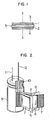
- the electric double layer capacitor basically includes a pair of polarizable electrode units formed by activated carbon layers 1 and 2 and collector electrodes 3 and 4, and a separator 5 interposed between the polarizable electrodes.
- the activated carbon layers 1 and 2 and the separator 5 are impregnated with an electrolyte.
- the electric double layer capacitors of this basic construction are roughly divided into the following three types of specific constructions.
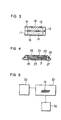
- the first type is constructed by applying a mixture 6 of activated charcoal powder and an organic binder such as fluorine resin powder onto aluminum nets 7, coiling the aluminum nets 7 together with separators 8, placing in a metal can 9 and hermetically sealing the can 9 with a rubber sealing cap 10.
- the coiled assembly is impregnated with an electrolyte composed of an aqueous solution of sulfuric acid or the like, or an organic mixture of tetraethyl ammonium perchlorate and propylene charbonate or the like as mentioned previously, and numerals 11 and 12 designate electrode leads.
- the second type shown in Fig.
- the third type is the one (Japanese Laid-Open Patent Application No. 55-99714 Publication No. 60-15138) which is invented by the inventors and employs activated carbon fibers as polarizable electrodes.
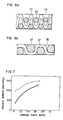
- Fig. 4 showing the third type capacitor, activated carbon fiber fabrics 20 and 21 which are respectively formed with metal sprayed coatings 22 and 23 are arranged opposite to each through the intermediary of a separator 24 and are hermetically assembled with a gasket 25 and metal cases 26 and 27. Since this type can be formed into a flat coin shape, is easy to manufacture and is small in size and high in capacitance, the third type is suitable for miniature circuits for the back-up use in microcomputers.
- U.S. 4562511 discloses a capacitor which uses an activated carbon fiber for its polarizable electrodes.
- the manner of weaving the fibers into the fabric has an important effect on the characteristics of the capacitor having the thus formed fabric. More specifically, the higher the proportion of the fibers entering the inside of the fabric is, the harder it will be for the activation gas (e.g., water vapor, C0 2 or HC) to sufficiently penetrate into the surface of the fibers at the inside during the activation, thus impeding the progress of the uniform activation for the fabric as a whole. Therefore, in order to satisfactorily promote the uniform activation of the fabric as a whole, it is impossible to obtain the desired specific surface area per unit weight unless the activation temperature is greatly increased or the activation time is increased. However, if the activation temperature is increased or the activation time is increased, the strength of the resulting activated carbon fabric is heavily decreased thereby rendering the activated fabric unsuitable for use.
- the activation gas e.g., water vapor, C0 2 or HC
- an electric double layer capacitor including a pair of polarizable electrodes wherein each of the polarizable electrodes comprises an element including activated carbon fibers, the carbon fibers include a plurality of micropores of pore size 2 x 10- 9 m (20A) or more, characterised in that the electrodes have a ratio of the total geometric surface area of a fabric to the total geometric surface area of secondary fibers of 0.01 or more wherein secondary fibers consist of a collective body of primary fibers.
- activated carbon fibers means one which is in the form of a woven fabric, nonwoven fabric, felt or the like composed of activated carbon fibers.
- the electric double layer capacitor of the invention is one (e.g., a capacitor of the form shown in Fig. 4) employing polarizable electrodes made of a woven fabric, nonwoven fabric, felt, or the like composed of at least activated carbon fibers as one of its constituent ingredients and more particularly the one in which these polarizable electrodes are high in capacitance value per unit area and unit weight and low in internal resistance.
- the invention features the construction (the weaving method, specific weight, etc.), materials and carbonization and activation processes of the polarizable electrodes.
- a capacitor having polarizable electrodes made of an activated carbon fabric such as the present invention
- the type of weaving of the fibers for forming the fabric governs the various properties of the resulting activated carbon fabric and hence the characteristics of a capacitor having the electrodes. More specifically, the higher the proportion of the fibers entering the inside of a fabric, the harder it will be for an activation gas (e.g., water vapor, C0 2 or HC) to satisfactorily enter and contact the surface of the fiber at the inside of the fabric during the activation process, thereby making the uniform progress of the activation difficult on the whole.
- an activation gas e.g., water vapor, C0 2 or HC
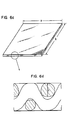
- Fig. 5 shows an example of an apparatus for activating a raw fabric.
- a raw fabric 31 accommodated within a furnace 30 is carbonized and activated by being contacted with an activation gas supplied from an activation gas supply unit 33 at a high temperature in the furnace 30 which is controlled by a control unit 32.
- an activation gas supply unit 33 supplied from an activation gas supply unit 33 at a high temperature in the furnace 30 which is controlled by a control unit 32.
- the proportion of fibers 35 positioned at the surface of a fabric 34 is small as compared with the amount of fibers entering the inside of the fabric in the thickness direction thereof as shown in Fig. 6a, during the activation processing, only the activation of the surface of the fabric progresses, while, the progress of the activation of the inside of the fabric is rendered difficult.
- the proportion of the fibers exposed to the surface is defined as (total geometric surface area of fabric/total geometric surface area of secondary fibers or strands) and it is referred to as a surface fiber ratio.
- the surface fiber ratio is calculated by the following method on the basis of the dimensions shown in Figs. 6c and 6d.
- the total geometric surface area S 2 of secondary fibers or strands is obtained by the following method.
- Fig. 7 shows the relation between the surface fiber ratio (total geometric surface area of fabric/total geometric surface area of secondary fibers or strands) and the specific surface area of the fiber, after it has been activated, with respect to raw fiber fabrics (hereinafter referred to as raw fabrics) comprised of phenol type fiber fabrics having weight (g/m 2 ) of 200 g/m 2 .
- raw fabrics hereinafter referred to as raw fabrics
- the solid line shows the relation achieved by activation for 30 minutes at 800 C and the broken line shows the relation achieved by activation for 2 hours at 800 C.
- Fig. 8 shows the fiber strength of the activated fabrics (activated carbon fabrics) as a function of the surface fiber ratio of the fabrics.
- Fig. 9 showing the characteristics of the electric double layer capacitors produced by using the above-mentioned activated carbon fabrics
- the abscissa represents the surface fiber ratio and the ordinate represents the capacitance (farad). It shows that the output capacitance increases in proportion to the value of the surface fiber ratio.
- the values represent the single-cell capacitances with the electrodes of 5 mm 0.
- the element In the case of an element made of the activated carbon fibers having a large surface fiber ratio, the element is fully activated uniformly throughout the whole element (particularly in the thickness direction) and thus the capacitance of the activated carbon fibers in the thickness direction of the element is satisfactorily taken out with low resistance to the conductive electrode layer at the surface.
- the present invention requires the use of an activated carbon fabric made by a weaving method which produces a surface fiber ratio of 0.01 or more.
- the first method has recourse to the selection of a weaving method of the secondary fibers and the second method has recourse to the selection of the primary fibers forming the secondary fibers.
- the diameter of the secondary fibers used in the invention is in the range from No. 1 size to No. 40 size, the primary fibers used have a small diameter and the primary fibers are bundled into the secondary fibers thereby increasing the effective fiber area per unit area of the fabric.
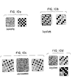
- Figs. 10a to 10d are schematic diagrams showing various weaving methods of raw fabrics with Fig. 10a showing a plain weave, Fig. 10b a twill weave, Fig. 10c a satin weave and Fig. 10d a basket weave, and these weaves represent the principal ones.
- Fig. 10a shows a plain weave
- Fig. 10b a twill weave
- Fig. 10c a satin weave
- Fig. 10d a basket weave
- these weaves represent the principal ones.
- Figs. 11 a to 11 show the relation between the primary and secondary fibers and the fabrics with Fig. 11 a showing a plain fabric 42 woven by using secondary fibers 41 of 0.5 mm diameter made by bundling primary fibers 40 of 0.2 gm diameter and 100 mm long, Fig. 11 a plain fabric 45 woven by using secondary fibers 44 of 0.5 mm diameter made by bundling primary fibers 43 of 10 lim diameter and 100 mm long and Fig. 10c a plain fabric 47 woven by directly using continuous filaments 46 of 0.5 mm diameter as primary fibers.
- the activation gas contacts and reacts with the surface of the fibers in a greater extent in the order of Figs. 11 c, 11 b and 11 a.
- This section describes the correlation between the weight loss and shrinkage due to the activation of raw fabrics and the capacitance of electric double layer capacitors using the resulting activated carbon fabrics and also a description is made of the feature of the invention concerning the optimum range of unit-area weights for obtaining the desired capacitance of the capacitor on the basis of the results of the study of the correlation.
- Fig. 12 is a flow sheet for the carbonization and activation of a raw fabric, in which numeral 50 designates a raw fabric, 51 a carbon fiber fabric, 52 an activated carbon fiber fabric, A a carbonization and activation process, B a carbonization process and C an activation process.
- the carbonization process B causes the gasification of the volatile compounds in the raw fabric 50 and the destructive carbonization of the fabric.
- Activation process C forms small pores in the surface of the carbonized fiber fabric 51 by a reaction of the following equation (1) thereby increasing the specific surface area
- the carbonization and activation process A causes the two processes B and C to proceed simultaneously and continuously. Each of these processes causes a loss of the weight and area of the raw fabric and serves as a measure of the degree of progress of the carbonization and activation reaction.
- the degree of progress of the carbonization and activation reaction has a significant effect on the characteristics of an electric double layer capacitor in which the fabric is used as its electrodes.
- Fig. 13 is a graph showing the relation between the weight loss or area loss caused by carbonization and activation of the fabrics and the capacitance of the capacitor, which shows that the maximum capacitance value (per unit area fabric) is obtained when the weight loss of the raw fabric shown by the curve (a) is from 60% to 90% and the area loss of the raw fabric shown by the curve (b) is from 30% to 70%. Note that the ordinate represents the capacitance ratio (%) with the capacitance value corresponding to the maximum capacitance output per unit area taken as 100.
- Fig. 14 shows a characteristic curve of the capacitance of a capacitor using the activated carbon fabrics resulting from the carbonization and activation of raw fabrics, with the abscissa representing "raw fabric weight (g/ M 2 )" and the ordinate representing weight loss value or area loss value corresponding to the capacitance ratio peak of 100% in Fig. 13. This tendency remains the same even if the unit-area weight of the raw fabrics is varied over a wide range.
- Fig. 15 shows the relation between the weight loss of the fabrics due to the carbonization and activation and the capacitance of electric double layer capacitors using the fabrics for the electrodes at 25 C and -25 C, respectively.
- the capacitance at 25° C gradually increases with increase in the weight loss due to the activation and the peak is attained at around 60%.
- the capacitance at -25 C rapidly increases in response to a weight loss of about 70% and thereafter the capacitance varies closely following the curve of the capacitance at 25 ⁇ C.
- the graph shows the values of the capacitors using two electrodes of 10 mm 0.
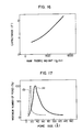
- Fig. 16 is a graph showing the relation between the weight (g/m 2 ) of raw fabrics and the capacitance of capacitors using the resulting activated carbon fabrics for the electrodes.
- the capacitances of the capacitors having two electrodes of 10 mm ⁇ are shown as in the case of Fig. 15.
- the capacitance values of this Figure are those obtained by discharge tests at 10 mA. From the Figure it will be seen that a capacitance value of 1.3 F is obtained with the two electrodes of 10 mm 0 made of the raw fabric having a unit-area weight of 500 g/m 2 and this results in the following equation:
- the optimum fabric unit-area weight for obtaining a capacitance value of 1 F/m 2 is 0.06 g/m 2.
- the discharge current is 10 mA and thus considering the discharge at a greater or smaller current than this value the optimum fabric unit-area weight for obtaining a capacitance value of 1 F/(m 2 of activated carbon fabric) is in the range between 0.002 g/m 2 and 0.2 g/m 2 .
- the suitable range of fabric unit-area weights is from 20 g/m 2 to 1000 g/m 2 . If the unit-area weight of the fabric is less than this range, the fabric is extremely open in weave and it is difficult to maintain the shape of the fabric. On the other hand, if the unit-area weight of the fabric is greater than the range, the finished thickness exceeds 1.5 mm and this is also not preferable from the standpoint of the surface fiber ratio described in the first section.
- a pore size of 2x10- 9 m (20 A) or more of micropores in the activated carbon fiber is necessary for an electric double layer capacitor to function effectively.
- the suitable range of values is disclosed for example in the invention of the inventors in Japanese Patent Application No. 58-13456 laid open as JP-A-59-67617, corresponding to EP-A-0112923).
- the activated carbon of (A) exhibits sufficiently high capacitance values both at room temperature and at low temperatures, while, the activated carbon of (B) exhibits substantially the same capacitance values as (A) at room temperature but considerably lower capacitance values at low temperatures.
- This difference in temperature characteristics is caused by the relation between the pore size and the thickness (2 to 3 x 10- 9 m (2 to 3 ⁇ )) of the electric double layers.
- a suitable activated carbon for the polarizable electrodes of the electric double layer capacitor must meet the essential requirement of having a high specific surface area and including uniformly a large number of pores of a size over 2x10- 9 m (20 ⁇ ).
- this essential requirement can be met relatively easily by means of stirring or the like during the manufacture.
- Figs. 19a to 19c are enlarged views for explaining a pre-activation raw fabric and the progress of activation of the fiber.
- Fig. 19a shows the raw fabric which is not subjected to the carbonization and activation processes as yet and it is composed of warp threads 55 and woof threads 56 which are made by twisting together fine primary fibers.
- the fabric has a thickness of 0.5 to 2 mm.
- the activation of this fabric with water vapor gives rise to the following problems.
- the carbonization and activation by the water vapor is given as
- the carbonization and activation process is a reaction in which carbon is attacked by the oxygen atoms of H 2 0 molecules and the chance for contact between the H 2 0 molecules and the carbon fibers serves as a rate-determining factor for the rate of the reaction.
- the amount of water vapor is not sufficient, only fibers 58 present at the surface of a fabric 57 are activated and fibers 59 existing within the fabric 57 are not fully activated as shown by the sectional view of the fabric in Fig. 19b.
- the activation time is increased but the same amount of water vapor is used, as shown in Fig. 19c, fibers 61 inside a fabric 60 are activated optimally but fibers 62 in the vicinity of the surface are activated excessively.
- Table 1 shows the characteristics of the electric double layer capacitors constructed by stamping two electrodes of 10 mm 0 from activated carbon fabrics corresponding to Figs. 19b and 19c, respectively, and assembling the electrodes, along with separators and electrolyte, into the same form as shown in Fig. 4.
- Figs. 20a to 20c show the manner in which the shape of the pores of the activated carbon undergo changes in response to the progress of activation.
- the degree or frequency of contact between the activation gas and the fibers to be activated As regards the degree or frequency of contact between the activation gas and the fibers to be activated, the previously mentioned "surface fiber ratio" or the weaving method and the weight (g/m 2 ) of the fabric constitute an important governing factor. In addition to these factors, the amount of activation gas and the gas pressure mentioned in this section constitute another important factors.
- the polarizable electrodes of an electric double layer capacitor are made of an activated carbon fabric prepared by carbonizing and activating a raw fabric with water vapor of 2666 N/m 2 (20 mm Hg) or over in a high-temperature inert gas atmosphere.
- the water vapor having a high vapor pressure is supplied so that the absolute water content in the atmosphere is increased and thus the water vapor is introduced in a sufficient amount inside the fabric.
- any difference of the degree of progress of the activation reaction in the thickness direction of the fabrics is eliminated and uniform pores are formed throughout the fabric in a short period of time.
- the method of supplying the activation gas will be described in detail in connection with the description of examples later.
- This method features that a raw fabric is impregnated with water prior to its activation.
- This step has great advantages: 10 During the activation the impregnated water vaporizes and acts as an activation gas. (2) Since the fibers are preliminarily impregnated with water, the wetting properties of the fibers to the water vapor are improved and the contact oxidation reaction with the activation gas is effected smoothly.
- Fig. 21 is a characteristic diagram for explaining the effect of the invention and it shows the relation between the activation time and weight loss of a novolac fabric having a size of 10 cm x 10 cm, thickness of 1 mm and eyelet weight of 200 g/m 2.
- the activation temperature is 800 C and the activation gas is propane combustion gas.
- the curve A shows the data obtained by activating a fabric preliminarily impregnated with water as the present invention and the curve B shows the data of one activated by the conventional method.
- a weight loss of about 90% takes place in 20 minutes in the case of curve A and curve B shows a similar weight loss as curve A in 40 minutes which is double the time. This means that in accordance with the invention the activation progresses at a rate which is about two times the conventional rate.
- the solid lines show the relation between the activation time and the weight loss in the cases using the activation method of this invention and the broken lines show the relation in the cases using raw fabrics which were not impregnated with water.
- the curves A, B and C respectively correspond to the fabrics having unit-area weights (g/m 2 ) of 100 g/m 2 , 300 g/m 2 and 500 g/m 2 respectively and it will be seen that the rate of weight loss by the activation varies from 1.5 to 3 times for the same unit-area weights depending on whether the fabrics were impregnated with water and this effect increases with an increase in the unit-area weight. It is to be noted that the effect of the water impregnation increases in proportion to the impregnation time, although the effect differs depending on the unit-area weight of the raw fabric. Also, by adding for example alkali metal or alkaline earth metal ions to the impregnating water, it is possible to control the size of the pores formed during the activation by virture of the catalytic action of these ions.
- Fig. 23 shows an equivalent circuit of an electric double layer capacitor and considering each of the component parts as a small capacitor the internal resistance is conceivable as including (i) a resistance R 1 due to the resistance of the conductive electrodes themselves and the contact resistance between the conductive electrodes and the polarizable electrodes, (ii) the internal resistance of a polarizable electrode R 2 , (iii) an electric double layer capacitance C and (iv) the resistance of an electrolyte R 3 .
- R 1 is the resistance due to the aluminum electrodes themselves and the contact between the aluminum electrodes and the activated carbon layers
- R 2 is the resistance of the activated carbon layers themselves having an effect when taking the capacitance from the respective capacitor elements to the aluminum electrodes.
- the activated carbon layers contain acetylene black so that the resistances of the activated carbon layers are low enough and therefore the resistance R 2 is very small.
- the resistance R 2 is increased as will be mentioned below so that if nothing is done, the internal resistance increases and the capacitor is not suitable for high rate discharge.
- the carbonized non-activated fiber is low in electric resistance, its specific surface area is small and it is not suitable for the polarizable electrode.
- Figs. 24a and 24b are schematic diagrams of these capacitors.
- conductives acetylene black 71 are present between individual activated carbon particles 70 and the capacitance of a portion 73 remote from an aluminum electrode 72 is satisfactorily taken out due to the electric conductivity of an activated carbon layer 74.
- Fig. 24a showing the capacitor using the powdered activated carbon electrodes
- conductives acetylene black 71 are present between individual activated carbon particles 70 and the capacitance of a portion 73 remote from an aluminum electrode 72 is satisfactorily taken out due to the electric conductivity of an activated carbon layer 74.
- the present invention features the use of the following woven fabrics and nonwoven fabrics for the electrodes.
- the present invention comprises an electric double layer capacitor in which structural members such as woven or nonwoven fabrics made of activated carbon fibers and conductive wires are used as polarizable electrodes.
- Figs. 25a to 25e schematically show in enlarged form some examples of the polarizable electrode according to the invention.
- the examples are each composed of conductive wires 80 and activated carbon fibers 81.
- Fig. 25a shows a plain weave electrode using activated carbon fibers as warp threads and tantalum wires as woof threads.
- Fig. 25b shows a similar plain weave electrode in which practically almost all the warp and woof threads are activated carbon fibers and tantalum wires are used only partly. This construction also accomplishes the object of the invention.
- Fig. 25a to 25e schematically show in enlarged form some examples of the polarizable electrode according to the invention.
- the examples are each composed of conductive wires 80 and activated carbon fibers 81.
- Fig. 25a shows a plain weave electrode using activated carbon fibers as warp threads and tantalum wires as woof threads.
- Fig. 25b shows a similar plain weave electrode in which practically almost all
- Fig. 25c shows a plain weave electrode in which the warp and woof threads are secondary fibers made by twisting together primary fibers 82 of 2 pm diameter and tantalum wires 83 of 2 pm diameter in suitable proportions.
- Fig. 25d shows an electrode in which tantalum wires and activated carbon fibers are combined into a felt like form and this nonwoven form also meet the purpose of the invention.
- Fig. 25e shows a three-dimensional weave electrode made of tantalum wires and activated carbon fibers and this three-dimensional weave has the effect of ensuring positive electric contact between the conductive wires and the activated carbon fibers and further improving the effect of the invention.
- the one is to preliminarily blend and weave conductive wires and nonactivated fibers and activate the resulting fabric and the other is to weave conductive wires into an activated fabric.
- the former method metals having melting points higher than the activation temperature, e.g., tantalum, titanium and nichrome are suitable and aluminum, carbon fibers and the like are suitable materials in the case of the latter method.
- Fig. 26 shows schematically the effective function of the invention. More specifically, low resistance conductive wires 85 are woven into relatively high-resistance activated carbon fibers 84 so that the current collection of the whole activated carbon fiber layer 86 is improved and hence the delivery of the capacitance to a conductive layer 87 is improved. Thus, as will be described in connection with the description of examples, the internal resistance of the capacitor is decreased and the capacitance value per volume is increased.
- Novolak fibers (Novolak is a trademark) of 0.4 pm diameter and 100 mm long are bundled into secondary fibers of 100 pm and warp and woof threads each including two of the secondary fibers are woven into a plain fabric having a surface fiber ratio of 0.5.
- the fabric is held in an atmosphere of 800 C and activated with an activation gas such as water vapor or C0 2 for 30 minutes.
- an aluminum electrode is formed on one side of the fabric by plasma spray process and then disks of 5 mm 0 diameter are stamped from the fabric. Inserted between the two electrodes thus prepared is a separator.
- Two electrodes and a separator are impregnated with an electrolyte composed of propylene carbonate, y-butyrolactone and tetraethyl ammonium perchlorate and these elements are enclosed by a metal case through a gasket thereby assembling a flat-type capacitor.
- Table 2 shows the characteristics of the electric double layer capacitor provided in accordance with the invention.
- the fibers of the conventional capacitors were activated under the same conditions as the invention.
- a Kynol raw fabric (Kynol is a registered trademark) having a weight of 200 g/m 2 is carbonized by holding it in a combustion waste gas atmosphere of 700° C for 30 minutes.
- the resulting carbon fiber fabric is impregnated with a 1 % solution of NaOH in water, dried at room temperature for 1 hour, activated for 2 hours in a combustion waste gas furnace of 800 C and then washed in water and dried.
- the thus prepared activated carbon fabric has a weight of 100 g/m 2 and the weight loss is about 60%.
- disks of 10 mm diameter are stamped from the activated carbon fabric.
- the two activated carbon fabric disks are impregnated with an electrolyte comprising a mixture of propylene carbonate and 10 wt% of tetraethyl ammonium perchlorate and then assembled, along with a polypropylene separator (12 mm in diameter and 100 ⁇ m in thickness) and a metal case, into a button-type electric double layer capacitor as shown in Fig. 4.
- an electrolyte comprising a mixture of propylene carbonate and 10 wt% of tetraethyl ammonium perchlorate and then assembled, along with a polypropylene separator (12 mm in diameter and 100 ⁇ m in thickness) and a metal case, into a button-type electric double layer capacitor as shown in Fig. 4.
- Table 3 shows the characteristics of the electric double layer capacitor obtained according to this example and also shown for comparison purposes are the characteristics of a capacitor using an activated carbon fabric whose weight loss or decrease on activation is 10% and a capacitor using an activated carbon fabric with a weight loss or decrease of 95%.
- the activated carbon fabric used with the invention can be used with electrolytes of aqueous solution type and a case where sulfuric acid is used as the electrolyte will now be described by way of example.
- a Kynol raw fabric (Kynol is a registered trademark) having a weight of 200 g/m 2 is carbonized by holding it in a combustion waste gas atmosphere of 700 °C for 30 minutes.
- the resulting carbon fabric is impregnated with a 1% aqueous solution of NaOH, dried for 1 hour at room temperature, activated for 2 hours in a combustion waste gas furnace at 800 C and washed in water and dried.
- the thus prepared activated carbon fabric has a weight of 100 g/m 2 and the weight loss is about 60%.
- the surface of the activated carbon fabric is coated with a conductive carbon paint and dried after which the activated carbon fabric is stamped into disks of 10 mm diameter.
- the two activated carbon fabric disks are impregnated with an electrolyte composed of an aqueous solution of sulfuric acid and then assembled, along with a polypropylene separator (12 mm in diameter and 100 ⁇ m in thickness) and a corrosion-resisting metal case, into a button-type electric double layer capacitor as shown in Fig. 4.
- Table 4 shows the characteristics of the electric double layer capacitor obtained in accordance with this example and also shown for comparison are the characteristics of a capacitor using an activated carbon fabric whose weight loss due to activation is 10% and a capacitor using an activated carbon fabric with a weight loss of 95%.
- Fig. 27 shows an example of a water vapor supply method used with the present invention.
- a gas supplied from an inert gas bomb 90 e.g., nitrogen or argon is passed and bubbled through a bottle 92 in a holding tank 91 so that the gas is contacted with water 93 in the bottle 92 and bubbles are formed.
- the inert gas having a partial water vapor pressure of about 12263.6 N/m 2 (92 mm Hg) is supplied into a furnace proper 94.
- a Kynol raw fabric 95 having a weight of 200 g/m 2 is held at 800 C far 10 minutes thereby completing the activation in the furnace 94.
- Fig. 28 shows another example of the water vapor supply method used with the invention.
- the supply of water vapor is accomplished by means of a liquid vaporizing apparatus 100 basically comprising water 97 contained in a closed vessel 96, a porous absorber 98 composed of a glassfiber fabric or the like and disposed to partly contact with the water 97 and a heater 99 in partial contact with the porous absorber 98.
- a gas from an inert gas bomb 90 e.g., argon or nitrogen is introduced into the liquid vaporizing apparatus 100 through an inlet 101 so that water vapor is produced by the vaporizing action of the porous absorber 98 and the heater 99 and, using the insert gas as a carrier, the water vapor is supplied through an outlet 102 into a furnace proper 103 containing a Kynol raw fabric (Kynol is a registered trademark) having a weight of 200 g/m 2 .
- Numeral 105 designates an electric power controller for the heater 99 and this power control makes it possible to accurately control as desired the vapor supply per unit time.
- the fabric is activated at 800 C for 10 minutes with an inert gas flow of 5 t/min and a heater power of 0.1 kW.
- Both of the two different vapor supply methods are capable of supplying a large amount of water vapor and thereby accomplishing the optimum activation in a short period of time. While the effect of the invention is enhanced with an increase in the vapor pressure, the value of the optimum vapor pressure differs depending on the amount of input Kynol fabric, (Kynol is a registered trademark) activation temperature and time and so on.
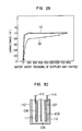
- Fig. 29 shows the correlation between the vapor pressures of the supplied vapor and the capacitance characteristics of an electric double layer capacitor using activated carbon fabrics made using the different vapor pressures.
- the electric double layer capacitors are made by the same method as the examples of the invention.
- curve A shows the capacitance values at room temperature
- curve B shows the capacitance values at -25 C. It will be seen from the Figure that a supply of vapor higher than 2666 N/m 2 (20 mm Hg) ensures a satisfactory room temperature capacitance and that vapor pressure lower than this value result in capacitance values close to zero.
- the example 5 can control the amount of vapor production irrespective of the temperature of the atmosphere and it is the effective one more suited to the purpose of the invention.
- Table 5 shows the characteristics of electric double layer capacitors produced by using activated carbon fabrics prepared by the methods of the examples 4 and 5.
- the electric double layer capacitors are made by the following method.
- the surface of an activated carbon fabric prepared by the previously mentioned activation is coated with an aluminum layer by a plasma spraying process and the thus formed activated carbon fabric with an A1 layer is stamped into disks of 10 mm 0.
- the two disk electrodes and a polypropylene separator of 100 mm thick are assembled into a coin type cell as shown in Fig. 4.
- the electrolyte used is a mixture of propylene carbonate and tetraethyl ammonium perchlorate.
- the table also shows for comparison the characteristics of a capacitor produced by using a vapor generator effecting the bubbling at 20 C to supply the water vapor for the activation and an activation time of 30 minutes.
- Fabrics A and B made of navolak phenol fibers (Novolak is a trademark) and respectively having weights of 100 g/m 2 and 500 g/m 2 are immersed in a distilled water for 10 minutes. After taking out from the water and subjecting to air drying for 5 minutes, the fabrics are held in a furnace for 10 minutes at 800 C. During the interval, nitrogen gas containing (a) propane combustion gas or (b) water vapor of 3999 N/m 2 (30 mm Hg) is introduced into the furnace. After the completion of the activation, a plasma sprayed coating of aluminum is formed on one surface of each of the fabrics and the fabrics are stamped into disks of 10 mm diameter. As shown in Fig.
- coin-type capacitors are assembled each using two of the fabric disks, a separator, an electrolyte comprising a mixture of propylene carbonate and tetraethyl ammonium perchlorate and a case.
- Table 6 shows the characteristics of the capacitors according to this example. The table also shows the characteristics of capacitors having activated carbon fibers prepared by the conventional methods which are the same as the present example, except that the step of impregnating the fabric with water prior to the activation is eliminated.
- a fabric made of novolak phenol fibers (Novolak is a trademark) and having a weight of 500 g/m 2 is immersed in an aqueous solution of 1 wt% calcium nitrate. After taking out from the solution and subjecting to air drying for 10 minutes, the fabric is held in a furnace for 30 minutes at 800 C. During this interval, propane combustion gas is introduced into the furnace. After the completion of the activation, the fabric is washed in water for 10 minutes, dried, coated by a plasma sprayed aluminum layer on one surface thereof and then stamped into disks of 10 mm ⁇ . As shown in Fig.
- a coin-type capacitor is assembled by using two of the thus prepared fabric electrodes, a separator, an electrolyte comprising an aqueous solution of 10 wt% sulfuric acid and a case.
- Table 7 shows the characteristics of the capacitor according to this example and the table also shows the characteristics of capacitors using activated carbon fabrics prepared by the conventional method which is the same as the present example except that the step of immersing the fabric in the calcium nitrate aqueous solution prior to the activation is eliminated.
- a plain fabric is made by using woof threads comprising secondary fibers of 500 ⁇ m diameter made by twisting together Kynol fibers (Kynol is a registered trademark) of 4 ⁇ m diameter and warp threads comprising tantalum wires of 500 ⁇ m diameter.
- the fabric is then activated by holding it in a propane combustion gas at 850 C.
- An aluminum layer of 100 ⁇ m thick is formed on one surface of the fabric by the plasma spray process and the fabric is stamped into disks of 10 mm diameter. As shown in Fig.
- a flat-type capacitor is assembled by using two of the disk electrodes, a polypropylene separator (100 ⁇ m in thickness) and an electrolyte comprising propylene carbonate and tetraethyl ammonium perchlorate.
- the same stranded wires of 500 ⁇ m diameter as used in example 9 and titanium wires of 500 ⁇ m diameter are woven in a three-dimensional manner as shown in Fig. 25e and a fabric is formed.
- the fabric is activated in a propane combustion gas at 850 C and a titanium electrode layer of 100 ⁇ m thick is formed on one surface of the fabric by the plasma spraying process.
- a capacitor is assembled in the same manner as in example 8.
- a fabric made of Kynol continuous filaments (Kynol is a registered trademark) of 500 ⁇ m diameter is activated in a propane combustion gas at 850 C.
- Aluminum wires of 300 ⁇ m diameter are woven into the activated carbon fabric and a plasma sprayed layer of aluminum is formed on one surface of the fabric.
- a capacitor is assembled by using two disk electrodes of 10 mm diameter stamped from the fabric, a separator and an electrolyte.
- Titanium wires of 10 ⁇ m diameter and Kynol fibers (Kynol is a registered trademark) of 4 ⁇ m diameter are blended and continuous filaments of 500 ⁇ m diamter are made. These continuous filaments are used as warp and woof threads and woven into a plain fabric.
- a titanium layer is formed on one surface of the fabric by the plasma spraying process.
- the fabric is then cut into strips of 3 cm x 10 cm and an electric double layer capacitor is made by assembling two strip electrodes 106 and 107, a polypropylene separator 108 and a sulfuric acid aqueous solution 109 of 0.1 mol/1 into a case 110.
- Numerals 111 and 112 designate sprayed titanium layers from which leads 113 and 114 are respectively brought out.
- Table 8 shows the characteristics of the electric double layer capacitors according to the foregoing five examples.
- the table also shows the characteristics of electric double layer capacitors of conventional constructions corresponding to these examples.
- the satin and basket weavings of fabrics are also effective.
- carbon paste layers may be used in place of the sprayed layers as the conductive electrodes.
Landscapes
- Engineering & Computer Science (AREA)
- Power Engineering (AREA)
- Microelectronics & Electronic Packaging (AREA)
- Chemical & Material Sciences (AREA)
- Textile Engineering (AREA)
- Manufacturing & Machinery (AREA)
- Materials Engineering (AREA)
- Inorganic Chemistry (AREA)
- Electric Double-Layer Capacitors Or The Like (AREA)
Claims (20)
Applications Claiming Priority (10)
| Application Number | Priority Date | Filing Date | Title |
|---|---|---|---|
| JP143652/83 | 1983-08-08 | ||
| JP58143652A JPS6035509A (ja) | 1983-08-08 | 1983-08-08 | 電気二重層キャパシタ |
| JP150930/83 | 1983-08-20 | ||
| JP58150930A JPS6043810A (ja) | 1983-08-20 | 1983-08-20 | 電気二重層キャパシタの製造法 |
| JP150929/83 | 1983-08-20 | ||
| JP58150929A JPS6043809A (ja) | 1983-08-20 | 1983-08-20 | 電気二重層キャパシタ |
| JP157172/83 | 1983-08-30 | ||
| JP58157172A JPS6050912A (ja) | 1983-08-30 | 1983-08-30 | 電気二重層キャパシタの製造法 |
| JP172123/83 | 1983-09-20 | ||
| JP58172123A JPS6064422A (ja) | 1983-09-20 | 1983-09-20 | 電気二重層キヤパシタおよびその製造法 |
Publications (3)
| Publication Number | Publication Date |
|---|---|
| EP0134706A2 EP0134706A2 (de) | 1985-03-20 |
| EP0134706A3 EP0134706A3 (en) | 1986-08-13 |
| EP0134706B1 true EP0134706B1 (de) | 1991-07-17 |
Family
ID=27527682
Family Applications (1)
| Application Number | Title | Priority Date | Filing Date |
|---|---|---|---|
| EP84305362A Expired - Lifetime EP0134706B1 (de) | 1983-08-08 | 1984-08-07 | Elektrischer Doppelschichtkondensator und Verfahren zu seiner Herstellung |
Country Status (2)
| Country | Link |
|---|---|
| EP (1) | EP0134706B1 (de) |
| DE (1) | DE3484812D1 (de) |
Cited By (7)
| Publication number | Priority date | Publication date | Assignee | Title |
|---|---|---|---|---|
| US6643119B2 (en) | 2001-11-02 | 2003-11-04 | Maxwell Technologies, Inc. | Electrochemical double layer capacitor having carbon powder electrodes |
| US6955694B2 (en) | 2000-05-12 | 2005-10-18 | Maxwell Technologies, Inc. | Electrochemical double layer capacitor having carbon powder electrodes |
| US7722686B2 (en) | 2004-02-19 | 2010-05-25 | Maxwell Technologies, Inc. | Composite electrode and method for fabricating same |
| US7791861B2 (en) | 2003-07-09 | 2010-09-07 | Maxwell Technologies, Inc. | Dry particle based energy storage device product |
| US7791860B2 (en) | 2003-07-09 | 2010-09-07 | Maxwell Technologies, Inc. | Particle based electrodes and methods of making same |
| US7859826B2 (en) | 2005-03-14 | 2010-12-28 | Maxwell Technologies, Inc. | Thermal interconnects for coupling energy storage devices |
| US7920371B2 (en) | 2003-09-12 | 2011-04-05 | Maxwell Technologies, Inc. | Electrical energy storage devices with separator between electrodes and methods for fabricating the devices |
Families Citing this family (11)
| Publication number | Priority date | Publication date | Assignee | Title |
|---|---|---|---|---|
| JPH07105316B2 (ja) * | 1985-08-13 | 1995-11-13 | 旭硝子株式会社 | 電気二重層コンデンサ用分極性電極及びその製造方法 |
| US5621607A (en) * | 1994-10-07 | 1997-04-15 | Maxwell Laboratories, Inc. | High performance double layer capacitors including aluminum carbon composite electrodes |
| US5862035A (en) * | 1994-10-07 | 1999-01-19 | Maxwell Energy Products, Inc. | Multi-electrode double layer capacitor having single electrolyte seal and aluminum-impregnated carbon cloth electrodes |
| US6233135B1 (en) | 1994-10-07 | 2001-05-15 | Maxwell Energy Products, Inc. | Multi-electrode double layer capacitor having single electrolyte seal and aluminum-impregnated carbon cloth electrodes |
| US6449139B1 (en) | 1999-08-18 | 2002-09-10 | Maxwell Electronic Components Group, Inc. | Multi-electrode double layer capacitor having hermetic electrolyte seal |
| US6739274B2 (en) | 2001-04-11 | 2004-05-25 | Albany International Corp. | End portions for a flexible fluid containment vessel and a method of making the same |
| US6860218B2 (en) | 2001-04-11 | 2005-03-01 | Albany International Corp. | Flexible fluid containment vessel |
| US6718896B2 (en) | 2001-10-30 | 2004-04-13 | Albany International Corp. | Fabric structure for a flexible fluid containment vessel |
| US7107921B2 (en) | 2001-10-30 | 2006-09-19 | Albany International Corp. | End portion for a flexible fluid containment vessel and a method of making the same |
| US6813139B2 (en) | 2001-11-02 | 2004-11-02 | Maxwell Technologies, Inc. | Electrochemical double layer capacitor having carbon powder electrodes |
| US7775171B2 (en) | 2003-01-21 | 2010-08-17 | Albany International Corp. | Flexible fluid containment vessel featuring a keel-like seam |
Family Cites Families (2)
| Publication number | Priority date | Publication date | Assignee | Title |
|---|---|---|---|---|
| US4014730A (en) * | 1973-08-03 | 1977-03-29 | Standard Oil Company | Polymer densified graphite sheet as impervious connector for an electrical capacitor |
| US4293396A (en) * | 1979-09-27 | 1981-10-06 | Prototech Company | Thin carbon-cloth-based electrocatalytic gas diffusion electrodes, and electrochemical cells comprising the same |
-
1984
- 1984-08-07 DE DE8484305362T patent/DE3484812D1/de not_active Expired - Lifetime
- 1984-08-07 EP EP84305362A patent/EP0134706B1/de not_active Expired - Lifetime
Cited By (9)
| Publication number | Priority date | Publication date | Assignee | Title |
|---|---|---|---|---|
| US6955694B2 (en) | 2000-05-12 | 2005-10-18 | Maxwell Technologies, Inc. | Electrochemical double layer capacitor having carbon powder electrodes |
| US6643119B2 (en) | 2001-11-02 | 2003-11-04 | Maxwell Technologies, Inc. | Electrochemical double layer capacitor having carbon powder electrodes |
| US6946007B2 (en) | 2001-11-02 | 2005-09-20 | Sony Corporation | Electrochemical double layer capacitor having carbon powder electrodes |
| US7791861B2 (en) | 2003-07-09 | 2010-09-07 | Maxwell Technologies, Inc. | Dry particle based energy storage device product |
| US7791860B2 (en) | 2003-07-09 | 2010-09-07 | Maxwell Technologies, Inc. | Particle based electrodes and methods of making same |
| US8072734B2 (en) | 2003-07-09 | 2011-12-06 | Maxwell Technologies, Inc. | Dry particle based energy storage device product |
| US7920371B2 (en) | 2003-09-12 | 2011-04-05 | Maxwell Technologies, Inc. | Electrical energy storage devices with separator between electrodes and methods for fabricating the devices |
| US7722686B2 (en) | 2004-02-19 | 2010-05-25 | Maxwell Technologies, Inc. | Composite electrode and method for fabricating same |
| US7859826B2 (en) | 2005-03-14 | 2010-12-28 | Maxwell Technologies, Inc. | Thermal interconnects for coupling energy storage devices |
Also Published As
| Publication number | Publication date |
|---|---|
| EP0134706A3 (en) | 1986-08-13 |
| EP0134706A2 (de) | 1985-03-20 |
| DE3484812D1 (de) | 1991-08-22 |
Similar Documents
| Publication | Publication Date | Title |
|---|---|---|
| US4597028A (en) | Electric double layer capacitor and method for producing the same | |
| EP0134706A2 (de) | Elektrischer Doppelschichtkondensator und Verfahren zu seiner Herstellung | |
| US3926671A (en) | Method of manufacturing positive nickel hydroxide electrodes | |
| DE69529316T2 (de) | Wiederaufladbare Batterien mit einer speziellen Anode und Verfahren zu ihrer Herstellung | |
| KR101683391B1 (ko) | 고성능 슈퍼커패시터 전극소재용 3차원 니켈폼/그래핀/니켈코발트산화물 복합체 및 이의 제조방법 | |
| US5366828A (en) | Metal alloy laded carbon aerogel hydrogen hydride battery | |
| AU686904B2 (en) | High performance double layer capacitors including aluminum carbon composite electrodes | |
| US4105513A (en) | Solid electrolyte capacitor having metallic cathode collector in direct contact with manganese dioxide electrolyte and method of producing same | |
| JP2001505363A (ja) | 電気的エネルギー貯蔵用大表面積窒化金属または金属オキシナイトライド | |
| US4263383A (en) | Zinc electrode | |
| US3258363A (en) | Carbonized polyvinylidenechloride fuel cell electrode | |
| US3410726A (en) | Electric cell with water repellant coated porous layer and method of making said layer | |
| DE68927435T2 (de) | Alkalische Sammlerbatterie und Verfahren zur Herstellung ihrer negativen Elektrode | |
| US3877987A (en) | Method of manufacturing positive nickel hydroxide electrodes | |
| EP0750360B1 (de) | Elektrodensubstrat für Batterie und Verfahren zu deren Herstellung | |
| US5100748A (en) | Structure of nickel hydroxide-based electrode doped with cobalt for an electrochemical generator | |
| JP2009200065A (ja) | キャパシタ用発泡状ニッケルクロム集電体およびそれを用いた電極、キャパシタ | |
| JP2010140941A (ja) | キャパシタ | |
| US5045349A (en) | Silver-nickel composite cathodes for alkaline secondary batteries | |
| US3522094A (en) | Electrode including hydrophobic polymer,method of preparation and fuel cell therewith | |
| EP0448854B1 (de) | Verbessertes Verfahren zur Herstellung einer Nickelhydroxyd enthaltenden Kathode für alkalische Batterien | |
| JP4822555B2 (ja) | キャパシタ用不織布状ニッケルクロム集電体及びこれを用いた電極、キャパシタ | |
| Varga et al. | Electrochemical pressure-composition isotherms for amorphous Ni1− xZrx alloys | |
| JP2008227380A (ja) | 電気二重層キャパシタ用分極性電極及びその製造方法 | |
| JPS63114061A (ja) | アルカリ蓄電池用焼結式ニツケル極の製法 |
Legal Events
| Date | Code | Title | Description |
|---|---|---|---|
| PUAI | Public reference made under article 153(3) epc to a published international application that has entered the european phase |
Free format text: ORIGINAL CODE: 0009012 |
|
| AK | Designated contracting states |
Designated state(s): DE FR GB |
|
| PUAL | Search report despatched |
Free format text: ORIGINAL CODE: 0009013 |
|
| AK | Designated contracting states |
Kind code of ref document: A3 Designated state(s): DE FR GB |
|
| 17P | Request for examination filed |
Effective date: 19870116 |
|
| 17Q | First examination report despatched |
Effective date: 19890224 |
|
| GRAA | (expected) grant |
Free format text: ORIGINAL CODE: 0009210 |
|
| AK | Designated contracting states |
Kind code of ref document: B1 Designated state(s): DE FR GB |
|
| REF | Corresponds to: |
Ref document number: 3484812 Country of ref document: DE Date of ref document: 19910822 |
|
| ET | Fr: translation filed | ||
| PLBE | No opposition filed within time limit |
Free format text: ORIGINAL CODE: 0009261 |
|
| STAA | Information on the status of an ep patent application or granted ep patent |
Free format text: STATUS: NO OPPOSITION FILED WITHIN TIME LIMIT |
|
| 26N | No opposition filed | ||
| REG | Reference to a national code |
Ref country code: GB Ref legal event code: 746 Effective date: 19960628 |
|
| REG | Reference to a national code |
Ref country code: GB Ref legal event code: IF02 |
|
| PGFP | Annual fee paid to national office [announced via postgrant information from national office to epo] |
Ref country code: GB Payment date: 20030806 Year of fee payment: 20 |
|
| PGFP | Annual fee paid to national office [announced via postgrant information from national office to epo] |
Ref country code: FR Payment date: 20030808 Year of fee payment: 20 |
|
| PGFP | Annual fee paid to national office [announced via postgrant information from national office to epo] |
Ref country code: DE Payment date: 20030814 Year of fee payment: 20 |
|
| PG25 | Lapsed in a contracting state [announced via postgrant information from national office to epo] |
Ref country code: GB Free format text: LAPSE BECAUSE OF EXPIRATION OF PROTECTION Effective date: 20040806 |
|
| REG | Reference to a national code |
Ref country code: GB Ref legal event code: PE20 |