EP0134746B1 - Antrieb durch Verwandeln von Wechsel-Linear-Bewegung in Drehbewegung - Google Patents
Antrieb durch Verwandeln von Wechsel-Linear-Bewegung in Drehbewegung Download PDFInfo
- Publication number
- EP0134746B1 EP0134746B1 EP84450021A EP84450021A EP0134746B1 EP 0134746 B1 EP0134746 B1 EP 0134746B1 EP 84450021 A EP84450021 A EP 84450021A EP 84450021 A EP84450021 A EP 84450021A EP 0134746 B1 EP0134746 B1 EP 0134746B1
- Authority
- EP
- European Patent Office
- Prior art keywords
- wheel
- chain
- belt
- teeth
- shaft
- Prior art date
- Legal status (The legal status is an assumption and is not a legal conclusion. Google has not performed a legal analysis and makes no representation as to the accuracy of the status listed.)
- Expired
Links
- 230000001131 transforming effect Effects 0.000 description 4
- BASFCYQUMIYNBI-UHFFFAOYSA-N platinum Chemical compound [Pt] BASFCYQUMIYNBI-UHFFFAOYSA-N 0.000 description 2
- 230000009191 jumping Effects 0.000 description 1
- 230000003137 locomotive effect Effects 0.000 description 1
- 230000003287 optical effect Effects 0.000 description 1
- 229910052697 platinum Inorganic materials 0.000 description 1
- 238000011144 upstream manufacturing Methods 0.000 description 1
Images


Classifications
-
- F—MECHANICAL ENGINEERING; LIGHTING; HEATING; WEAPONS; BLASTING
- F16—ENGINEERING ELEMENTS AND UNITS; GENERAL MEASURES FOR PRODUCING AND MAINTAINING EFFECTIVE FUNCTIONING OF MACHINES OR INSTALLATIONS; THERMAL INSULATION IN GENERAL
- F16H—GEARING
- F16H19/00—Gearings comprising essentially only toothed gears or friction members and not capable of conveying indefinitely-continuing rotary motion
- F16H19/02—Gearings comprising essentially only toothed gears or friction members and not capable of conveying indefinitely-continuing rotary motion for interconverting rotary or oscillating motion and reciprocating motion
- F16H19/06—Gearings comprising essentially only toothed gears or friction members and not capable of conveying indefinitely-continuing rotary motion for interconverting rotary or oscillating motion and reciprocating motion comprising flexible members, e.g. an endless flexible member
- F16H19/0622—Gearings comprising essentially only toothed gears or friction members and not capable of conveying indefinitely-continuing rotary motion for interconverting rotary or oscillating motion and reciprocating motion comprising flexible members, e.g. an endless flexible member for converting reciprocating movement into oscillating movement and vice versa, the reciprocating movement is perpendicular to the axis of oscillation
-
- F—MECHANICAL ENGINEERING; LIGHTING; HEATING; WEAPONS; BLASTING
- F16—ENGINEERING ELEMENTS AND UNITS; GENERAL MEASURES FOR PRODUCING AND MAINTAINING EFFECTIVE FUNCTIONING OF MACHINES OR INSTALLATIONS; THERMAL INSULATION IN GENERAL
- F16H—GEARING
- F16H27/00—Step-by-step mechanisms without freewheel members, e.g. Geneva drives
- F16H27/02—Step-by-step mechanisms without freewheel members, e.g. Geneva drives with at least one reciprocating or oscillating transmission member
-
- F—MECHANICAL ENGINEERING; LIGHTING; HEATING; WEAPONS; BLASTING
- F16—ENGINEERING ELEMENTS AND UNITS; GENERAL MEASURES FOR PRODUCING AND MAINTAINING EFFECTIVE FUNCTIONING OF MACHINES OR INSTALLATIONS; THERMAL INSULATION IN GENERAL
- F16H—GEARING
- F16H31/00—Other gearings with freewheeling members or other intermittently driving members
- F16H31/001—Mechanisms with freewheeling members
Definitions
- the present invention relates to a drive device by transforming an alternating linear movement into continuous movement.
- the document FR-A-756.886 describes a device of the above kind, with free wheels, intended to drive a shaft from chains controlled by members driven by rectilinear reciprocating movements.
- Such a device has the disadvantages of freewheeling devices, namely, the cost, the fragility and the limitation of the torque likely to be transmitted.
- the aim of the present invention is to overcome these various drawbacks by proposing a simple and robust means capable of transforming an alternating linear movement into a discontinuous or continuous rotary movement, by transmitting significant forces and capable of lending itself to easy speed regulation. of rotation in rotary movement or of the amplitude and frequency of the discontinuous rotary movement.
- the subject of the invention is a drive device by transforming a linear movement into a rotary movement, characterized in that it comprises a toothed wheel secured to an axis to be driven in rotation and mounted in a swivel in a bearing carried by a frame, a chain or belt, or the like, passing over said wheel and fixed, at one end, to a movable reciprocating motor member following a rectilinear trajectory along an axis substantially tangent to the toothed wheel and, at the other end, to an automatic return means, the teeth of the wheel being shaped so that in the return direction of the chain or belt, the latter "jumps" onto said teeth without driving them, while in the opposite direction the chain or belt is in firm engagement with the teeth of the wheel.
- said motor member is the rod of a jack fixed to said frame, while said return means is a helical spring also fixed to said frame.
- Such a device is capable of transforming the reciprocating movement of the piston of the jack into a discontinuous rotary movement of said axis to be driven by transmitting forces which can be very great, these being supported without any problem and with great robustness and security by the chain-gear pair.
- the device of the invention it is possible to communicate to said axis to cause a rotation which is no longer discontinuous but continuous by juxtaposing at least two devices according to the invention, that is to say by securing in rotation each toothed wheel of the same axis to be driven and by operating the jacks or engine members with a certain offset, so that at the end of the engine movement of one of the jacks the relay is taken up by the other jack, or the next jack so as to ensure the continuous rotation of said axis.
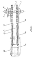
- the device shown in FIG. 1 comprises a toothed wheel 1 keyed onto a shaft or axis 2 to be driven in rotation and mounted in a journalled manner in a bearing 3 fixed on a frame 4.
- the teeth 5 of the wheel 1 have a special profile which will be described later.
- a chain 6 with conventional links one end of which is fixed to a helical spring 7 anchored at its other end to a lug 8 secured to the frame 4 and the other end of which is fixed to a rod 9 of a jack 10, hydraulic, pneumatic, electric, etc., also fixed to the frame 4.
- the axes of the spring 7 and of the rod 9 are substantially parallel and tangent to the toothed wheel 1.
- the device also includes, optionally, a non-return valve 11 which can be replaced by a friction system on the side of the wheel 1 or on the shaft 2.
- the teeth 5 of the wheel 1 are asymmetrical and have a curved leading flank 5a in correspondence with the curvature of the axes of the chain links 6 in order to mesh securely and stably with said axes when the chain 6 is towed by the rod 9.
- each tooth 5 is inclined along a slope extending to the foot of the upstream tooth (in the direction of drive of the wheel 1 by the chain 6).
- the flank 5b extends over a angular sector has much more spread out than angular sector 0 (very narrow) on which the sidewall 5a extends so as to have a slope as close as possible to a tangent to the wheel 1.
- the non-return device 11 is used when the inertia of the device driven by the shaft 2 is low and is not sufficient to compensate for the rear force exerted by the friction of the chain 6 on the teeth 5.
- the wheel 1 has dimensions adapted to the force to be transmitted; it can be double, triple, etc. by juxtaposition and keying on the same shaft 2. The latter can be used at each of its ends to transmit the useful rotary movement.
- the chain 6 (for example a roller chain) has pitch and dimension characteristics in relation to the wheel 1 and the power of the movement to be transmitted.
- the jack 10 can be constituted by any other system producing an alternating linear movement.
- the coil spring 7 can be replaced by an elastic tensioner or a cylinder operating in opposition with the traction member 10, or any other system allowing the tension of the chain 6 and its restoring to be maintained.
- the frame 4 can have the shapes and dimensions required by the context in which it is used, in particular it can have a shape of platinum or box.
- the travel of the traction member 9,10 can be adjusted by stops, limit switches, electronic or optical systems, or any other means, so as to have a greater or lesser amplitude of the rotational movement of the wheel 1 .
- the adjustment of the frequency of the reciprocating movement determining the total speed in revolutions / minute of the wheel 1-shaft 2 assembly can be easily obtained by a timer system controlling the frequency of the forward and return cycles of the rod 9.
- FIG. 2 By juxtaposing two devices such as that of FIG. 1 on the same shaft 2, it is possible (FIG. 2) to communicate a continuous movement to said shaft.
- the device shown in fig. 2 comprises on the same frame 4, two jacks 10, 10 'mounted in parallel and pulling two chains 6, 6' also mounted in parallel and cooperating with two identical toothed tracks 1.1 'keyed onto the same shaft 2.
- the device according to the invention makes it possible in particular to transmit very large forces, in particular at slow speed, which could not be supported by fragile systems of the ratchet wheel type in particular.
- FIG. 3 illustrates an alternative embodiment according to which the toothed wheel 1 "has teeth 5" with a profile different from that of FIG. 1 and adapted to a toothed belt 6 "responsible for transmitting the movement of the rod 9 of the jack 10 to the 1 "wheel.
- the teeth 5 “have a meshing flank 5" a relatively stiff, close to a plane radial to the wheel, while the opposite flank 5 “b intended to allow the belt 6" to jump the teeth at the return is much more inclined to allow the projections or notches 6 "a of the belt, of trapezoidal or rectangular section, to slide and escape from the teeth 5".
- the device of FIG. 3 also includes a hauling assembly 12 interposed between the end of the belt 6 "and the end of the rod 9 of the jack and intended to multiply by 2, 3, 4 etc ... the power developed by the traction member 9, 10.
- This assembly 12 which is optional, can of course be mounted on the devices of FIGS. 1 and 2.
- the device of FIG. 3 can also include a non-return device if the inertia of the assembly driven by the wheel 1 "and the shaft 2 is not sufficient to prevent the wheel 1" from going backwards during return to the starting position of the 6 "belt.
- the invention is obviously not limited to the embodiments shown and described above, but on the contrary covers all variants thereof, in particular as regards the shapes and dimensions of the teeth of the toothed wheel (1, 1 ' , 1 ”) and the nature of the means of traction of the chain, belt or the like (6, 6") and means (7) for returning the latter.
Landscapes
- Engineering & Computer Science (AREA)
- General Engineering & Computer Science (AREA)
- Mechanical Engineering (AREA)
- Transmission Devices (AREA)
- Devices For Conveying Motion By Means Of Endless Flexible Members (AREA)
- Ultra Sonic Daignosis Equipment (AREA)
- Vehicle Body Suspensions (AREA)
- Forging (AREA)
Claims (8)
Priority Applications (1)
| Application Number | Priority Date | Filing Date | Title |
|---|---|---|---|
| AT84450021T ATE28925T1 (de) | 1983-09-09 | 1984-09-10 | Antrieb durch verwandeln von wechsel-linearbewegung in drehbewegung. |
Applications Claiming Priority (2)
| Application Number | Priority Date | Filing Date | Title |
|---|---|---|---|
| FR8314573 | 1983-09-09 | ||
| FR8314573A FR2551823B1 (fr) | 1983-09-09 | 1983-09-09 | Dispositif d'entrainement par transformation d'un mouvement lineaire alternatif en mouvement rotatif |
Publications (2)
| Publication Number | Publication Date |
|---|---|
| EP0134746A1 EP0134746A1 (de) | 1985-03-20 |
| EP0134746B1 true EP0134746B1 (de) | 1987-08-12 |
Family
ID=9292180
Family Applications (1)
| Application Number | Title | Priority Date | Filing Date |
|---|---|---|---|
| EP84450021A Expired EP0134746B1 (de) | 1983-09-09 | 1984-09-10 | Antrieb durch Verwandeln von Wechsel-Linear-Bewegung in Drehbewegung |
Country Status (4)
| Country | Link |
|---|---|
| EP (1) | EP0134746B1 (de) |
| AT (1) | ATE28925T1 (de) |
| DE (1) | DE3465375D1 (de) |
| FR (1) | FR2551823B1 (de) |
Families Citing this family (1)
| Publication number | Priority date | Publication date | Assignee | Title |
|---|---|---|---|---|
| GB2188392B (en) * | 1986-03-25 | 1990-03-14 | Ceretech Ltd | Rotary drive |
Family Cites Families (4)
| Publication number | Priority date | Publication date | Assignee | Title |
|---|---|---|---|---|
| FR679008A (fr) * | 1928-11-08 | 1930-04-08 | Condensation Application Mec | Dispositif transformateur de mouvement |
| FR756886A (fr) * | 1932-02-10 | 1933-12-16 | Système de transformation de mouvement permettant l'utilisation de toute force atmosphérique, hydraulique, naturelle, mécanique, humaine ou autre | |
| FR754534A (fr) * | 1933-04-19 | 1933-11-08 | Les Fils De Peugeot Freres | Dispositif de commande à pédale |
| FR1032829A (fr) * | 1951-02-19 | 1953-07-06 | Système de transmission de mouvement transformant une commande à courses alternatives en une rotation |
-
1983
- 1983-09-09 FR FR8314573A patent/FR2551823B1/fr not_active Expired
-
1984
- 1984-09-10 EP EP84450021A patent/EP0134746B1/de not_active Expired
- 1984-09-10 DE DE8484450021T patent/DE3465375D1/de not_active Expired
- 1984-09-10 AT AT84450021T patent/ATE28925T1/de not_active IP Right Cessation
Also Published As
| Publication number | Publication date |
|---|---|
| FR2551823B1 (fr) | 1988-05-27 |
| ATE28925T1 (de) | 1987-08-15 |
| FR2551823A1 (fr) | 1985-03-15 |
| EP0134746A1 (de) | 1985-03-20 |
| DE3465375D1 (en) | 1987-09-17 |
Similar Documents
| Publication | Publication Date | Title |
|---|---|---|
| EP0277447B1 (de) | System zur Ermittlung der Bewegung eines Raupenfahrzeuges | |
| CA2238965C (fr) | Mecanisme d'entrainement a ressort pour un appareil de commutation, en particulier un disjoncteur | |
| EP0522984A1 (de) | Kettenrad für Fahrräder | |
| FR2496801A1 (fr) | Accouplement a roue libre | |
| FR2885656A1 (fr) | Boitier de transmission pour engin roulant notamment a conducteur marchant | |
| EP0134746B1 (de) | Antrieb durch Verwandeln von Wechsel-Linear-Bewegung in Drehbewegung | |
| EP0755833A1 (de) | Kraftfahrzeugscheibenwischer mit Mitteln zur Begrenzung der Anhebung des Scheibenwischerarms | |
| FR2546454A1 (fr) | Vehicule de travail autopropulse | |
| EP0270430B1 (de) | Bewegungswandler, besonders Untersetzungsgetriebe | |
| WO2010135847A1 (fr) | Dispositif d'enroulement d'un lien souple | |
| FR2658892A1 (fr) | Poulie menee d'une transmission a vitesse variable. | |
| FR2664956A1 (fr) | Variateur continu de vitesse a chaine. | |
| EP0675022B1 (de) | Elektrischer Schalter für Fahrtrichtungsanzeige eines Fahrzeugs | |
| FR2700531A1 (fr) | Dispositif de traction sur câble. | |
| FR2797670A1 (fr) | Dispositif de transmission de mouvement a variation de vitesse | |
| FR3152299A1 (fr) | Transmission du type à cardan pour véhicule | |
| FR2476256A1 (fr) | Roue de transmission a diametre variable | |
| FR2539730A1 (fr) | Treuil a adherence | |
| FR3129899A1 (fr) | Boitier différentiel intégrant un dispositif de frein de parking et un dispositif de déconnexion de roues d'un véhicule automobile | |
| FR2802887A1 (fr) | Dispositif d'entrainement a chenille souple pour vehicule a moteur | |
| FR2864599A1 (fr) | Dispositif de serrage et de desserrage d'un frein de parking motorise | |
| FR2766251A1 (fr) | Dispositif d'entrainement et de transmission | |
| EP0064423A1 (de) | Trommelbremse, insbesondere für Lastkraftwagen | |
| FR2923798A1 (fr) | Perfectionnement pour pedalier. | |
| FR2478240A1 (fr) | Perfectionnements aux entraineurs unidirectionnels a cliquets |
Legal Events
| Date | Code | Title | Description |
|---|---|---|---|
| PUAI | Public reference made under article 153(3) epc to a published international application that has entered the european phase |
Free format text: ORIGINAL CODE: 0009012 |
|
| AK | Designated contracting states |
Designated state(s): AT BE CH DE GB IT LI LU NL SE |
|
| 17P | Request for examination filed |
Effective date: 19850916 |
|
| 17Q | First examination report despatched |
Effective date: 19860612 |
|
| GRAA | (expected) grant |
Free format text: ORIGINAL CODE: 0009210 |
|
| AK | Designated contracting states |
Kind code of ref document: B1 Designated state(s): AT BE CH DE GB IT LI LU NL SE |
|
| REF | Corresponds to: |
Ref document number: 28925 Country of ref document: AT Date of ref document: 19870815 Kind code of ref document: T |
|
| ITF | It: translation for a ep patent filed | ||
| REF | Corresponds to: |
Ref document number: 3465375 Country of ref document: DE Date of ref document: 19870917 |
|
| PG25 | Lapsed in a contracting state [announced via postgrant information from national office to epo] |
Ref country code: LU Free format text: LAPSE BECAUSE OF NON-PAYMENT OF DUE FEES Effective date: 19870930 |
|
| PGFP | Annual fee paid to national office [announced via postgrant information from national office to epo] |
Ref country code: NL Payment date: 19870930 Year of fee payment: 4 |
|
| PLBE | No opposition filed within time limit |
Free format text: ORIGINAL CODE: 0009261 |
|
| STAA | Information on the status of an ep patent application or granted ep patent |
Free format text: STATUS: NO OPPOSITION FILED WITHIN TIME LIMIT |
|
| 26N | No opposition filed | ||
| PG25 | Lapsed in a contracting state [announced via postgrant information from national office to epo] |
Ref country code: AT Effective date: 19880910 |
|
| PG25 | Lapsed in a contracting state [announced via postgrant information from national office to epo] |
Ref country code: SE Effective date: 19880911 |
|
| PG25 | Lapsed in a contracting state [announced via postgrant information from national office to epo] |
Ref country code: NL Effective date: 19890401 |
|
| NLV4 | Nl: lapsed or anulled due to non-payment of the annual fee | ||
| PG25 | Lapsed in a contracting state [announced via postgrant information from national office to epo] |
Ref country code: GB Effective date: 19890910 |
|
| PG25 | Lapsed in a contracting state [announced via postgrant information from national office to epo] |
Ref country code: LI Effective date: 19890930 Ref country code: CH Effective date: 19890930 Ref country code: BE Effective date: 19890930 |
|
| BERE | Be: lapsed |
Owner name: GILLET MARCEL Effective date: 19890930 |
|
| GBPC | Gb: european patent ceased through non-payment of renewal fee | ||
| REG | Reference to a national code |
Ref country code: CH Ref legal event code: PL |
|
| PG25 | Lapsed in a contracting state [announced via postgrant information from national office to epo] |
Ref country code: DE Effective date: 19900601 |
|
| EUG | Se: european patent has lapsed |
Ref document number: 84450021.5 Effective date: 19890712 |