EP0134824B1 - Porte saillante coulissant latéralement - Google Patents
Porte saillante coulissant latéralement Download PDFInfo
- Publication number
- EP0134824B1 EP0134824B1 EP83107995A EP83107995A EP0134824B1 EP 0134824 B1 EP0134824 B1 EP 0134824B1 EP 83107995 A EP83107995 A EP 83107995A EP 83107995 A EP83107995 A EP 83107995A EP 0134824 B1 EP0134824 B1 EP 0134824B1
- Authority
- EP
- European Patent Office
- Prior art keywords
- gate
- guide rollers
- rollers
- sideways
- supporting
- Prior art date
- Legal status (The legal status is an assumption and is not a legal conclusion. Google has not performed a legal analysis and makes no representation as to the accuracy of the status listed.)
- Expired
Links
Images


Classifications
-
- E—FIXED CONSTRUCTIONS
- E05—LOCKS; KEYS; WINDOW OR DOOR FITTINGS; SAFES
- E05D—HINGES OR SUSPENSION DEVICES FOR DOORS, WINDOWS OR WINGS
- E05D15/00—Suspension arrangements for wings
- E05D15/06—Suspension arrangements for wings for wings sliding horizontally more or less in their own plane
- E05D15/0617—Suspension arrangements for wings for wings sliding horizontally more or less in their own plane of cantilever type
-
- E—FIXED CONSTRUCTIONS
- E05—LOCKS; KEYS; WINDOW OR DOOR FITTINGS; SAFES
- E05D—HINGES OR SUSPENSION DEVICES FOR DOORS, WINDOWS OR WINGS
- E05D15/00—Suspension arrangements for wings
- E05D15/06—Suspension arrangements for wings for wings sliding horizontally more or less in their own plane
- E05D15/0621—Details, e.g. suspension or supporting guides
- E05D15/066—Details, e.g. suspension or supporting guides for wings supported at the bottom
- E05D15/0691—Top guides
-
- E—FIXED CONSTRUCTIONS
- E05—LOCKS; KEYS; WINDOW OR DOOR FITTINGS; SAFES
- E05F—DEVICES FOR MOVING WINGS INTO OPEN OR CLOSED POSITION; CHECKS FOR WINGS; WING FITTINGS NOT OTHERWISE PROVIDED FOR, CONCERNED WITH THE FUNCTIONING OF THE WING
- E05F15/00—Power-operated mechanisms for wings
- E05F15/60—Power-operated mechanisms for wings using electrical actuators
- E05F15/603—Power-operated mechanisms for wings using electrical actuators using rotary electromotors
- E05F15/632—Power-operated mechanisms for wings using electrical actuators using rotary electromotors for horizontally-sliding wings
- E05F15/635—Power-operated mechanisms for wings using electrical actuators using rotary electromotors for horizontally-sliding wings operated by push-pull mechanisms, e.g. flexible or rigid rack-and-pinion arrangements
- E05F15/641—Power-operated mechanisms for wings using electrical actuators using rotary electromotors for horizontally-sliding wings operated by push-pull mechanisms, e.g. flexible or rigid rack-and-pinion arrangements operated by friction wheels
-
- E—FIXED CONSTRUCTIONS
- E06—DOORS, WINDOWS, SHUTTERS, OR ROLLER BLINDS IN GENERAL; LADDERS
- E06B—FIXED OR MOVABLE CLOSURES FOR OPENINGS IN BUILDINGS, VEHICLES, FENCES OR LIKE ENCLOSURES IN GENERAL, e.g. DOORS, WINDOWS, BLINDS, GATES
- E06B11/00—Means for allowing passage through fences, barriers or the like, e.g. stiles
- E06B11/02—Gates; Doors
- E06B11/04—Gates; Doors characterised by the kind of suspension
- E06B11/045—Gates; Doors characterised by the kind of suspension exclusively for horizontally sliding gates
-
- E—FIXED CONSTRUCTIONS
- E05—LOCKS; KEYS; WINDOW OR DOOR FITTINGS; SAFES
- E05Y—INDEXING SCHEME ASSOCIATED WITH SUBCLASSES E05D AND E05F, RELATING TO CONSTRUCTION ELEMENTS, ELECTRIC CONTROL, POWER SUPPLY, POWER SIGNAL OR TRANSMISSION, USER INTERFACES, MOUNTING OR COUPLING, DETAILS, ACCESSORIES, AUXILIARY OPERATIONS NOT OTHERWISE PROVIDED FOR, APPLICATION THEREOF
- E05Y2201/00—Constructional elements; Accessories therefor
- E05Y2201/60—Suspension or transmission members; Accessories therefor
- E05Y2201/622—Suspension or transmission members elements
- E05Y2201/71—Toothed gearing
- E05Y2201/722—Racks
-
- E—FIXED CONSTRUCTIONS
- E05—LOCKS; KEYS; WINDOW OR DOOR FITTINGS; SAFES
- E05Y—INDEXING SCHEME ASSOCIATED WITH SUBCLASSES E05D AND E05F, RELATING TO CONSTRUCTION ELEMENTS, ELECTRIC CONTROL, POWER SUPPLY, POWER SIGNAL OR TRANSMISSION, USER INTERFACES, MOUNTING OR COUPLING, DETAILS, ACCESSORIES, AUXILIARY OPERATIONS NOT OTHERWISE PROVIDED FOR, APPLICATION THEREOF
- E05Y2900/00—Application of doors, windows, wings or fittings thereof
- E05Y2900/40—Application of doors, windows, wings or fittings thereof for gates
- E05Y2900/402—Application of doors, windows, wings or fittings thereof for gates for cantilever gates
Definitions
- the invention relates to a self-supporting side sliding door with a door leaf which is longer than the door opening width and which has a hollow profile, box-shaped lower flange and is guided between two double posts arranged at a distance and connected via an upper bridge link to the side of the door opening, the double posts being upper and include lower support and guide rollers for supporting the lower flange and the upper flange between them, and a further support roller is provided at a distance from the double posts for supporting the free end of the door in the open position below the door leaf.
- the door leaf is guided in the area of the upper chord by providing rollers arranged on the roller supports between the double posts, which act laterally and from above on the upper chord.
- the door leaf is guided in the area of the lower flange by collar rollers, which interact with a support and guide rail held on the lower flange and overlap the support and guide rail with their laterally provided collar extensions, or else there is a support in the lower flange - And guide rail provided. which is double T-shaped or U-shaped in cross section. so that the lower support and guide rollers can engage in this support rail.
- the support roller supporting the free end of the gate in the open position and arranged at a distance from the double post is designed as a collar roller or as a roller engaging in the profile of the support and guide rail, so that in the open position Door leaf is held securely against lateral displacement.
- the formation of the lower flange which is box-shaped in cross section, requires the arrangement of stiffening elements in the lower flange, in particular in the case of large sliding side gates.
- These stiffeners which generally consist of profile beams running in the longitudinal direction of the lower chord and spaced transverse webs, increase the weight of the door, the supporting and guide rails required for supporting the lower chord between the rollers provided in the double posts additionally increasing the weight and therefore require further reinforcement of the necessary bracing.
- the high weight of the door leaf leads to premature wear of the lower support rollers and the support and guide rails as well as the roller bearings and requires very large driving forces to move the door leaf.
- the invention has for its object to develop a cantilever side sliding door of the type mentioned so that the door leaf can be manufactured with significantly lower weight and maintains stability and torsional rigidity while maintaining the stability and torsion resistance allows a significantly simplified assembly and safe guidance of the door leaf without the risk of damage to the Carrier and guide rollers is achieved.
- the sliding gate mentioned according to the invention is characterized in that the upper and lower support and guide rollers or their supports between the double posts are each adjustable in height and side, and that the lower wall of the lower flange has a central longitudinal groove for engaging the has lower guide rollers and rests on the lower support rollers with their flat walls running laterally of the groove.
- the guide rollers engaging in the central longitudinal groove do not bear any weight, but only serve to hold the door in the specified direction of alignment in all positions.
- the support roller provided at a distance from the double posts for supporting the free end of the gate in the open position can also be designed as a smooth, non-profiled roller that extends over the entire width of the lower chord extends so that the lower chord with the flat walls running laterally to the central longitudinal groove on this roll for Aufla comes when the gate is moved to the open position. Any damage or signs of wear occur on the above. not at a distance from the double post provided support roller even with temperature-related thermal curvatures of the door leaf.
- the door leaf can be kept much easier compared to the known designs, it is possible to insert these with large length dimensions after the previous assembly of the double posts between the double posts and the height and side adjustability provided in the double posts Adjusting support and guide rollers, whereby the mentioned adjustability can also compensate for slight deviations that should occur when the double posts are set. Furthermore, it is possible, by means of the adjustability of the support and guide rollers, to adhere to the necessary tolerances which are necessary in order to ensure the smooth movement of the door even in the case of the deformation of the door leaf which has already been mentioned several times as a result of one-sided temperature effects.
- the guide rollers engaging in the central longitudinal groove of the lower flange are arranged offset in the longitudinal direction of the gate with respect to the support rollers acting on the lower flange. This results in an additional effort for the storage of the guide rollers on the one hand and the support rollers on the other hand, but this arrangement has the advantage that in the event of damage to the support rollers or their storage and a consequent loss of the load-bearing capacity of the support rollers, the gate is supported on the latter Support roles assigned guide role takes place.
- the guide roller thus serves to maintain emergency running properties for the door in the event of a functional failure of the associated support rollers.
- the lower support rollers arranged between one of the double posts can be connected to a drive device. This results in a frictional drive for the gate, which ensures safe operation of the gate due to the weight of the support rollers.
- one of the guide rollers engaging in the central longitudinal groove of the lower flange is connected to a drive device and is in engagement with a gall chain arranged in the groove base.
- the aforementioned arrangement presupposes the arrangement of the guide rollers offset in the longitudinal direction of the gate with respect to the support rollers assigned to it.
- This drive has the great advantage that the gall chain is protected against weather and external influences in the groove base and there is a positive connection between the guide roller acting as the drive wheel and the gall chain.
- the central longitudinal groove provided in the lower flange can have a different cross-sectional shape. It can be square or rectangular, but it is advisable to make it trapezoidal in cross-section and to adapt the guide rollers engaging in this groove to this trapezoidal shape. This results in particularly favorable conditions for the transmission of thrust forces between the guide roller and the lower flange without the fear of major signs of wear.
- the support rollers advantageously have at least one running surface made of a wear-resistant plastic, such as polyamide. while the lower guide grooves should expediently consist of a hard rubber material at least in the region of their side walls.
- the lower support rollers can also be designed overall as polyamide rollers, just as the support and guide rollers interacting with the upper belt expediently consist of polyamide or should have a running surface made of the material mentioned.
- the aforementioned design makes it possible to prefabricate the double posts including the upper bridge section and the lower crossbar as a structural unit and to anchor them in the ground at the installation site before the rollers for the door leaf with the associated support devices on the bridge link or on the lower crossbar arranged and the door leaf inserted between the double posts and adjusted by appropriate adjustment of the elements supporting the rollers.
- the drawing shows a schematic representation of an embodiment of the invention.
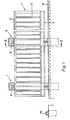
- the side sliding gate shown in FIGS. 1 and 2 consists of a door leaf 1 which is extended beyond the door opening width and which has an upper flange 2 and a lower flange 3 and connecting rods 4 arranged between them.
- the door leaf is held between double posts 5, which have the same design and are concreted in the substrate 6 at a distance from one another in the longitudinal direction of the door.
- the double posts 5 consist of parallel, identical actual posts 7, which can be designed in the form of a double-T profile or a U-profile and also as hollow profiles. At their upper ends, the posts 7 are connected via a bridge member 8 screwed to them in the form of a U-shaped part.
- the double post is covered at the top by a removable hood 10.
- the lower ends of the associated posts 7 are firmly connected to one another via a cross member 9, so that the posts 7 form a structural unit with the bridge member 8 and the cross member 9, which can be inserted into the ground 6 and anchored there.
- Fig. 2 shows that both the top flange 2 and the bottom flange 3 of the door leaf 1 are designed as hollow profiles, the bottom flange 3 being box-shaped in cross section.
- the door leaf 1 is supported and guided both on the upper chord 2 and on the lower chord 3, specifically by means of supporting and guide rollers which are arranged and designed differently.
- Lateral guide rollers 11 rest on the upper flange 2, which are attached to a cross member 12 which can be adjusted in height and on the side and can be held in such a way that the rollers 11 are in turn still adjustable relative to one another.
- Supporting rollers 13 which cooperate with the upper wall of the upper chord are also provided on the cross member 12 and, like the lateral guide rollers 11, are held in corresponding bearing blocks.
- screws 14 are provided at the same time for adjusting the height of the cross member 12.
- the lower wall of the lower flange 3 is provided with a central longitudinal groove 15 into which a guide roller 16 adapted to the groove cross section engages.
- a guide roller 16 adapted to the groove cross section engages.
- which in the example shown is held between two cylindrical support rollers 17 arranged on the same shaft or axis, on which the flat walls 18 provided laterally next to the groove 15 rest.
- the central longitudinal groove is trapezoidal in cross section and the guide roller 16 is adapted in its outline to the groove 15.
- the guide roller 16 is freely rotatably held on the shaft carrying the support rollers 17, so that it can carry out its rotary movements independently of the support rollers 17.
- the support rollers 17 and the guide roller 16 are held with their common shaft in bearing blocks 19, which in turn are screwed to a base plate 20 so that side adjustability is ensured.
- the base plate 20 is in turn connected to the crossbar 9 via adjusting screws, so that their height and lateral position can be adjusted with respect to the door leaf 1.
- the shaft connected to the support rollers 17 is designed as a drive shaft, i. H. the support rollers 17 are held against rotation on the shaft which is connected to a drive motor 21 via a releasable coupling (not shown in the drawing).
- Both the upper support and guide rollers 11 and 13 and the lower support rollers 17 are provided with a tread made of polyamide.
- the lower guide roller 16 can also consist of a wear-resistant plastic or a hard rubber material.
- FIG. 3 In the plan view shown in FIG. 3 of an arrangement of the lower support and guide rollers which deviates from FIGS. 1 and 2, the separate mounting of the support rollers 17 and the guide roller 16 can be seen on the illustrated base plate 20.
- the support rollers 17 are arranged on a common axis or shaft, while in this example the guide roller 16 is connected in a rotationally secure manner to a drive shaft 22 which is connected in a rotationally secure manner to the drive motor 21 via a schematically indicated coupling 23.
- common bearing blocks 19 are provided, which are connected in the manner described to the base plate 20 by means of screws so as to be laterally adjustable.
- Fig. 3 shows a circumferential profile 24 of the guide roller 16, which cooperates for engagement with a gall chain provided in the bottom of the trapezoidal longitudinal groove 15 of the lower flange, but not shown in the drawing.
- the arrangement according to FIG. 3 has, in addition to the advantage that a non-positive transmission of the driving force from the motor 21 to the door leaf 1, the further advantage that if the supporting function of the support rollers 17 fails, the door leaf is temporarily supported by the guide roller 16 is and thus the gate in the most favorable position for operation or repair can be transferred without the function of the failed support rollers.
- the support rollers 17, like the additional support roller 25 shown in FIG. 1 and spaced apart from the double posts 5, are designed as smooth rollers, since they do not have to perform any guiding function in the configuration of the gate described.
- the arrangement of the central longitudinal groove 15 in the lower wall of the lower flange 3 is a such reinforcement of the lower flange achieved that additional internals, in particular longitudinal rails, are not required. It is also possible to dispense with the otherwise necessary lower support and guide rails, with which the lower support and guide rollers usually interact.
- the lower flange 3 can be produced in the extrusion process, or it can also be converted in a relatively simple manner by folding flat sheets into the shape shown in the figures, without the need for major welding work.
Landscapes
- Engineering & Computer Science (AREA)
- Mechanical Engineering (AREA)
- Civil Engineering (AREA)
- Structural Engineering (AREA)
- Gates (AREA)
- Ultra Sonic Daignosis Equipment (AREA)
- Magnetically Actuated Valves (AREA)
- Adjustment Of Camera Lenses (AREA)
- Barrages (AREA)
Claims (9)
Priority Applications (3)
| Application Number | Priority Date | Filing Date | Title |
|---|---|---|---|
| AT83107995T ATE21143T1 (de) | 1983-08-12 | 1983-08-12 | Freitragendes seitenschiebetor. |
| EP83107995A EP0134824B1 (fr) | 1983-08-12 | 1983-08-12 | Porte saillante coulissant latéralement |
| DE8383107995T DE3364948D1 (en) | 1983-08-12 | 1983-08-12 | Cantilevered side sliding gate |
Applications Claiming Priority (1)
| Application Number | Priority Date | Filing Date | Title |
|---|---|---|---|
| EP83107995A EP0134824B1 (fr) | 1983-08-12 | 1983-08-12 | Porte saillante coulissant latéralement |
Publications (2)
| Publication Number | Publication Date |
|---|---|
| EP0134824A1 EP0134824A1 (fr) | 1985-03-27 |
| EP0134824B1 true EP0134824B1 (fr) | 1986-07-30 |
Family
ID=8190630
Family Applications (1)
| Application Number | Title | Priority Date | Filing Date |
|---|---|---|---|
| EP83107995A Expired EP0134824B1 (fr) | 1983-08-12 | 1983-08-12 | Porte saillante coulissant latéralement |
Country Status (3)
| Country | Link |
|---|---|
| EP (1) | EP0134824B1 (fr) |
| AT (1) | ATE21143T1 (fr) |
| DE (1) | DE3364948D1 (fr) |
Cited By (1)
| Publication number | Priority date | Publication date | Assignee | Title |
|---|---|---|---|---|
| DE9310090U1 (de) * | 1993-07-07 | 1995-02-16 | Adronit Verwaltungsgesellschaft mbH, 58300 Wetter | Freitragendes Schiebetor |
Families Citing this family (18)
| Publication number | Priority date | Publication date | Assignee | Title |
|---|---|---|---|---|
| EP0392053B1 (fr) * | 1989-04-13 | 1993-06-09 | Malkmus-Dörnemann, Carola, Dr. | Porte saillante coulissant latéralement |
| BE1012951A3 (nl) | 1999-10-29 | 2001-06-05 | Bekaert Sa Nv | Schuifpoort. |
| FR2819845B1 (fr) | 2001-01-19 | 2003-08-29 | Tordo Belgrano Sa | Dispositif de guidage d'un vantail coulissant par rapport a une ouverture |
| JP4599140B2 (ja) * | 2004-02-17 | 2010-12-15 | 三菱重工業株式会社 | 可動柵と可動柵の開閉方法 |
| JP4365768B2 (ja) * | 2004-11-17 | 2009-11-18 | 三菱重工業株式会社 | プラットホームドア装置 |
| GB2434393A (en) * | 2006-01-18 | 2007-07-25 | Strongarm Ltd | Barrier system for restricting vehicular access to a roadway |
| GB2451110A (en) * | 2007-07-18 | 2009-01-21 | Parking Facilities Ltd | Cantilever gate having an external drive system |
| AT508632B1 (de) * | 2009-09-07 | 2012-06-15 | Czapek Rudolf | Schiebetor |
| CN102287131A (zh) * | 2011-07-27 | 2011-12-21 | 无锡帝安福科技有限公司 | 组装式悬臂门 |
| US11136800B2 (en) * | 2011-09-30 | 2021-10-05 | Charles Larsen | Gate roller with tapered side walls and related methods |
| CN103850588A (zh) * | 2012-12-03 | 2014-06-11 | 北新集团建材股份有限公司 | 一种推拉门窗及其制作方法 |
| CN109356109B (zh) * | 2018-12-10 | 2024-02-13 | 中国电建集团贵阳勘测设计研究院有限公司 | 一种平面闸门的双向限位装置 |
| CN109356110B (zh) * | 2018-12-10 | 2024-02-13 | 中国电建集团贵阳勘测设计研究院有限公司 | 一种平面闸门的侧反向定轮装置 |
| IT201900001975A1 (it) * | 2019-02-12 | 2020-08-12 | F A C S R L | Dispositivo di fine-corsa per cancelli scorrevoli auto-portanti e cancello scorrevole auto-portante comprendente un simile dispositivo di fine corsa |
| CN109930946B (zh) * | 2019-04-18 | 2025-03-07 | 江苏龙腾门业有限公司 | 一种多重叠防脱轨平衡机库门 |
| CN113153126B (zh) * | 2020-01-23 | 2026-02-17 | 红门智能科技股份有限公司 | 一种平移门 |
| CN113153125B (zh) * | 2020-01-23 | 2026-03-03 | 红门智能科技股份有限公司 | 一种平移门及平移门组装方法 |
| IT202200027087A1 (it) * | 2022-12-29 | 2024-06-29 | Puglia Mecc S R L | Barriera mobile scorrevole |
Family Cites Families (6)
| Publication number | Priority date | Publication date | Assignee | Title |
|---|---|---|---|---|
| DE1683259C3 (de) * | 1966-12-07 | 1974-11-21 | Carola Dr. 3320 Salzgitter Malkmus-Doernemann Geb. Doernemann | Freitragendes Schiebetor |
| DE2743007C2 (de) * | 1977-09-23 | 1984-04-26 | Hörmann KG Antriebs- und Steuerungstechnik, 4834 Harsewinkel | Schiebetor mit einem Sockelbalken und einem auf diesem befestigten Toraufbau |
| GB2067636B (en) * | 1980-01-08 | 1983-05-11 | Whillock A | Sliding door arrangement |
| FR2477210A1 (fr) * | 1980-03-03 | 1981-09-04 | Mecaneral | Dispositif de manoeuvre d'ouverture de portes lourdes |
| DE8227840U1 (de) * | 1982-10-05 | 1982-11-25 | Hespe & Woelm Gmbh & Co Kg, 5628 Heiligenhaus | Rollenbock fuer ein freitragendes schiebetor |
| DE8232878U1 (de) * | 1982-11-24 | 1983-04-28 | Joh. Jos. Volberg Verwaltungsgesellschaft Mbh & Co Kg, 5060 Bergisch Gladbach | Schiebetor (ii) |
-
1983
- 1983-08-12 EP EP83107995A patent/EP0134824B1/fr not_active Expired
- 1983-08-12 AT AT83107995T patent/ATE21143T1/de not_active IP Right Cessation
- 1983-08-12 DE DE8383107995T patent/DE3364948D1/de not_active Expired
Cited By (1)
| Publication number | Priority date | Publication date | Assignee | Title |
|---|---|---|---|---|
| DE9310090U1 (de) * | 1993-07-07 | 1995-02-16 | Adronit Verwaltungsgesellschaft mbH, 58300 Wetter | Freitragendes Schiebetor |
Also Published As
| Publication number | Publication date |
|---|---|
| ATE21143T1 (de) | 1986-08-15 |
| EP0134824A1 (fr) | 1985-03-27 |
| DE3364948D1 (en) | 1986-09-04 |
Similar Documents
| Publication | Publication Date | Title |
|---|---|---|
| EP0134824B1 (fr) | Porte saillante coulissant latéralement | |
| EP1314626A1 (fr) | Porte coulissante et pivotante pour véhicules, notamment porte des passagers pour véhicules de transport urbain de personnes | |
| DE3602520A1 (de) | Deckengliedertor und fuehrungszwischenstueck fuer die laufrollen des obersten torblattgliedes | |
| DE4435641C2 (de) | Schiebeflügel zum bedarfsweisen Verschließen, insbesondere einer offenen Seite von Balkonen, Wintergärten u. dgl. | |
| DE9418079U1 (de) | Freitragendes Schiebetor | |
| DE1929305C3 (de) | Rampe zur abwechselnden Verbindung einer Zufahrt mit mehreren, übereinander angeordneten Stockwerkböden einer Garage od.dgl | |
| EP0936119A1 (fr) | Porte pivotante coulissante pour véhicules | |
| DE9200973U1 (de) | Einschienenhängebahn | |
| DE1559961C3 (de) | Freitragendes Schiebetor | |
| EP0392053B1 (fr) | Porte saillante coulissant latéralement | |
| EP0078484B1 (fr) | Dispositif de parcage pour véhicules automobiles | |
| EP0008082A1 (fr) | Garage pour garer les véhicules l'un au-dessus de l'autre | |
| CH676457A5 (fr) | ||
| AT374151B (de) | Schwenkschiebetuer | |
| DE10210247A1 (de) | Schnellauftor | |
| EP0030983A1 (fr) | Dispositif pour garer deux voitures l'une sur l'autre | |
| DE1169983B (de) | Gueterwagen, insbesondere gedeckter Gueter-wagen, mit in geschlossenem Zustand in einer Ebene liegenden Schiebewaenden | |
| DE2418932A1 (de) | Schwenkvorrichtung fuer die platten eines vertikalfoerderers | |
| DE10308155A1 (de) | Vertikal-Sektional-Schiebetor | |
| EP0490094B1 (fr) | Pont démontable et véhicule pour la pose du pont | |
| DE2950564C2 (de) | Hallendach mit Schiebedachelementen | |
| DE3227795A1 (de) | Versenkbare leitplanke | |
| EP1084980B1 (fr) | Chariot, de préférence chariot distributeur de grue | |
| DE1291312B (de) | Walzgeruest mit in einer gemeinsamen Ebene angeordneten Horizontalwalzen | |
| DE3610892A1 (de) | Sektionalschiebewand |
Legal Events
| Date | Code | Title | Description |
|---|---|---|---|
| PUAI | Public reference made under article 153(3) epc to a published international application that has entered the european phase |
Free format text: ORIGINAL CODE: 0009012 |
|
| AK | Designated contracting states |
Designated state(s): AT BE CH DE FR GB LI |
|
| 16A | New documents despatched to applicant after publication of the search report | ||
| 17P | Request for examination filed |
Effective date: 19850419 |
|
| GRAA | (expected) grant |
Free format text: ORIGINAL CODE: 0009210 |
|
| AK | Designated contracting states |
Kind code of ref document: B1 Designated state(s): AT BE CH DE FR GB LI |
|
| REF | Corresponds to: |
Ref document number: 21143 Country of ref document: AT Date of ref document: 19860815 Kind code of ref document: T |
|
| REF | Corresponds to: |
Ref document number: 3364948 Country of ref document: DE Date of ref document: 19860904 |
|
| ET | Fr: translation filed | ||
| PLBE | No opposition filed within time limit |
Free format text: ORIGINAL CODE: 0009261 |
|
| STAA | Information on the status of an ep patent application or granted ep patent |
Free format text: STATUS: NO OPPOSITION FILED WITHIN TIME LIMIT |
|
| 26N | No opposition filed | ||
| PGFP | Annual fee paid to national office [announced via postgrant information from national office to epo] |
Ref country code: FR Payment date: 19940729 Year of fee payment: 12 |
|
| PGFP | Annual fee paid to national office [announced via postgrant information from national office to epo] |
Ref country code: GB Payment date: 19940801 Year of fee payment: 12 |
|
| PGFP | Annual fee paid to national office [announced via postgrant information from national office to epo] |
Ref country code: BE Payment date: 19940812 Year of fee payment: 12 |
|
| PGFP | Annual fee paid to national office [announced via postgrant information from national office to epo] |
Ref country code: CH Payment date: 19940822 Year of fee payment: 12 |
|
| PGFP | Annual fee paid to national office [announced via postgrant information from national office to epo] |
Ref country code: AT Payment date: 19940831 Year of fee payment: 12 |
|
| PG25 | Lapsed in a contracting state [announced via postgrant information from national office to epo] |
Ref country code: GB Effective date: 19950812 Ref country code: AT Effective date: 19950812 |
|
| PG25 | Lapsed in a contracting state [announced via postgrant information from national office to epo] |
Ref country code: LI Effective date: 19950831 Ref country code: CH Effective date: 19950831 Ref country code: BE Effective date: 19950831 |
|
| PGFP | Annual fee paid to national office [announced via postgrant information from national office to epo] |
Ref country code: DE Payment date: 19951013 Year of fee payment: 13 |
|
| BERE | Be: lapsed |
Owner name: MALKMUS-DORNEMANN CAROLA DR Effective date: 19950831 |
|
| GBPC | Gb: european patent ceased through non-payment of renewal fee |
Effective date: 19950812 |
|
| REG | Reference to a national code |
Ref country code: CH Ref legal event code: PL |
|
| PG25 | Lapsed in a contracting state [announced via postgrant information from national office to epo] |
Ref country code: FR Effective date: 19960430 |
|
| REG | Reference to a national code |
Ref country code: FR Ref legal event code: ST |
|
| PG25 | Lapsed in a contracting state [announced via postgrant information from national office to epo] |
Ref country code: DE Effective date: 19970501 |