EP0134858A1 - Herstellung von Synthesegas aus schweren Kohlenwasserstoffen, die einen hohen Metallgehalt haben - Google Patents
Herstellung von Synthesegas aus schweren Kohlenwasserstoffen, die einen hohen Metallgehalt haben Download PDFInfo
- Publication number
- EP0134858A1 EP0134858A1 EP83305542A EP83305542A EP0134858A1 EP 0134858 A1 EP0134858 A1 EP 0134858A1 EP 83305542 A EP83305542 A EP 83305542A EP 83305542 A EP83305542 A EP 83305542A EP 0134858 A1 EP0134858 A1 EP 0134858A1
- Authority
- EP
- European Patent Office
- Prior art keywords
- gas
- stream
- synthesis gas
- water
- hot
- Prior art date
- Legal status (The legal status is an assumption and is not a legal conclusion. Google has not performed a legal analysis and makes no representation as to the accuracy of the status listed.)
- Granted
Links
Images
Classifications
-
- C—CHEMISTRY; METALLURGY
- C01—INORGANIC CHEMISTRY
- C01B—NON-METALLIC ELEMENTS; COMPOUNDS THEREOF; METALLOIDS OR COMPOUNDS THEREOF NOT COVERED BY SUBCLASS C01C
- C01B3/00—Hydrogen; Gaseous mixtures containing hydrogen; Separation of hydrogen from mixtures containing it; Purification of hydrogen; Reversible storage of hydrogen
- C01B3/02—Production of hydrogen; Production of gaseous mixtures containing hydrogen
- C01B3/32—Production of hydrogen; Production of gaseous mixtures containing hydrogen by reaction of gaseous or liquid organic compounds with gasifying agents, e.g. water, carbon dioxide or air
- C01B3/34—Production of hydrogen; Production of gaseous mixtures containing hydrogen by reaction of gaseous or liquid organic compounds with gasifying agents, e.g. water, carbon dioxide or air by reaction of hydrocarbons with gasifying agents
- C01B3/36—Production of hydrogen; Production of gaseous mixtures containing hydrogen by reaction of gaseous or liquid organic compounds with gasifying agents, e.g. water, carbon dioxide or air by reaction of hydrocarbons with gasifying agents using oxygen; using mixtures containing oxygen as gasifying agents
Definitions
- This invention relates to the partial oxidation of a liquid hydrocarbon fuel to produce synthesis gas. More specifically, it relates to a process for simultaneously producing two clean product streams of synthesis gas, one gas stream with a high and the other gas stream with a low, H 2 0/dry gas mole ratio by the partial oxidation of heavy hydrocarbon feedstocks containing high metal concentrations.
- the hot raw effluent gas stream from the reaction zone of a partial oxidation gas generator may comprise principally H 2 , C0, C0 2 , and H 2 0 together with other gasecus constituents, and minor amounts of entrained particulate matter, i.e., particulate carbon and ash.
- the hot, raw effluent gas must be cooled and cleaned to produce synthesis gas or fuel gas.
- Synthesis gas is important commercially as a source of feed gas for the synthesis of hydrocarbons or oxygen containing organic compounds, or for producing hydrogen or ammonia.
- Entrained particulate carbon and ash may be removed from the raw effluent gas by quenching and scrubbing with water such as described in coassigned U.S. Patent 3,232,728. Cleaning the effluent gas by scrubbing with an oil-carbon slurry is described in coassigned U.S. Patent 3,639,261. Recovery of the soot, from carbon-water dispersions in a carbon-recovery facility is described in coassigned U.S. Patent Numbers 2,999,741; 2,992,906; 3,044,179; and 4,134,740. Typical decanting procedures are described in coassigned U.S. Patent Numbers 3,980,592 and 4,014,786. These coassigned U.S. patents are incorporated herein by reference.
- the feedstock to a partial oxidation process for the simultaneous continuous production of two streams of cleaned synthesis gas having high and low H 2 0/dry gas mole ratios respectively may comprise a heavy hydrocarbon fuel containing high metal concentrations as well as all of the soot rich in metal valves recovered in the process.
- Two free-flow noncatalytic refractory lined partial oxidation gas generators are used. All of the hot raw synthesis gas produced in the first gas generator is quench cooled in water in a quench tank; and, siumltaneously, all of the hot raw synthesis gas produced in the second gas generator is split into two separate hot, raw gas streams. One of said split gas streams is quench cooled in water in a quench tank. Simultaneously, the other split gas stream is cooled in a convection-type gas cooler by indirect heat exchange with boiler feed water, without the tubes in the gas cooler plugging or fouling.
- the two quench cooled gas streams are combined and scrubbed free from particulate matter, i.e., particulate carbon and ash with water to produce a clean product stream of synthesis gas having a high H 2 0/dry gas mole ratio.
- the stream of synthesis gas leaving the gas cooler is separately scrubbed free from particulate matter to produce a clean product stream of synthesis gas having a low H 2 0/dry gas mole ratio.
- the streams of carbon-water- ash dispersion from all of the quench tanks and gas scrubbers is processed in a soot-recovery facility to separate clarified water, ash, and to produce a liquid dispersion of soot in water or in a liquid hydrocarbon ' carrier.
- All of this dispersion is then introduced into the first gas generator as a portion of thc liquid hydrocarbon fuel feed. Fouling and plugging of the tubes of a convection-type gas cooler associated with the second gas generator is prevented even though there is total carbon recycle in the process by: (1) lowering the fraction of ash in the gas stream going to the gas cooler due to split flow, and (2) decreasing the total metals in the feed to the second gas generator by eliminating the metals normally recycled in the soot recycle.
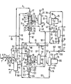
- Synthesis gas generator 1 is fed with a fuel mixture from line 3 which comprises heavy liquid hydrocarbon fuel containing high concentrations of metal compounds from line 4 and a liquid dispersion of soot containing metals in a liquid carrier from line 5 by way of a conventional soot recovery facility 6 as previously described.
- the heavy liquid hydrocarbon fuel in line 4 is pumped by means of pump 7 through line 8, heater .9 (optional), and lines 10 and 11 into mixer 14 where it is mixed with the liquid dispersion of soot from line 5.
- Part of the hydrocarbon fuel feedstock in line 10 is preferably sent to soot-recovery facility 6 by way of line 56, valve 57, and line 58 to provide the bulk of the liquid carrier for the soot in line 5.
- the fuel mixture in line 20 is mixed in line 3 with a temperature moderator such as steam from line 99.
- the mixture of fuel and steam in line 3 is introduced into the free-flow noncatalytic reaction zone 15, lined with thermal insulating refractory 16, of gas generator 1 by way of one passage in burner 17 located in the top of gas generator 1.
- a stream of free-oxygen containing gas from line 18 is passed through line 19 and is introduced into reaction zone 15 of gas generator 1 by way of another passage in burner 17.
- the autogenous partial oxidation of the fuel mixture then takes place in the reaction zone of gas generator 1 to produce a hot, raw synthesis gas stream containing unreacted entrained particulate carbon and ash.
- all of the hot raw synthesis gas stream is quench cooled and scrubbed with water in a quench tank located below the reaction zone.
- Flow control means 22 is a blank flange plate or valve located in the line upstream or downstream from gas cooler 29 for controlling the flow rate, or starting or stopping the passage of the split, hot, raw synthesis gas stream therethrough.
- the partially cleaned quench cooled stream of synthesis gas with most of the particulate carbon and ash removed leaves quench tank 27 by way of line 45 and is mixed with a second stream of partially cleaned quench cooled stream of synthesis gas from line 55, to be further described.
- the mixture of gases is passed through line 46, and into venturi scrubber 48 where it is scrubbed free of any remaining entrained particulate carbon and ash with water from line 47.
- the mixture of synthesis gas and liquid dispersion comprising particulate carbon, water; and ash enters gas scrubbing and separation column 49 through line 50.
- the liquid dispersion comprising particulate carbon, water, and ash in the bottom of quench tank 27 is passed through line 60, valve 61, line 62 and into line 63 where it is mixed with the dispersion comprising particulate carbon, water, and ash from lines 54 and 64 from separator 49.
- gas generator 1 During normal operation about 45 to 55 volume percent, such as 50 vol.% of the plant-design total synthesis gas output is produced by gas generator 1.
- gas generator 2 is also being operated to produce the remainder of the plant-design total synthesis gas output.
- synthesis gas generators 1 and 2 are substantially of the same size and produce gas at the same rate.
- Flow control means 85 in refractory lined line 86-87 is open, or alternatively flow control means such as valve 108 is open, and the hot raw synthesis gas produced in refractory lined reaction zone 88 of gas generator 2 is split into two gas streams in thermal refractory lined gas-diversion chamber 89.
- Flow control means 85 is a blank flange plate or valve located in the line upstream or downstream from gas cooler 101 for controlling the flow rate, or starting or stopping the passage of the split hot raw synthesis gas stream therethrough.
- Heavy hydrocarbon fuel feedstock containing high concentrations of metal compounds from line 4, pump 7, line 8, optional heater 9, lines 10 and 90 is mixed in line 91 with a temperature moderator such as steam from line 92.
- the mixture of fuel and steam is introduced into the reaction zone of gas generator 2 by way of one passage in burner 100.
- a stream of free-oxygen containing gas from line 18 is passed through line 96 and is introduced into reaction zone 88 of gas .generator 2 by way of burner 100.
- the raw effluent synthesis gas stream from reaction zone 88 in gas generator 2 is split into two hot, raw synthesis gas streams.
- the two split, raw synthesis gas streams may be produced at the same gas rate.
- the first split, hot raw synthesis gas stream may comprise about 10 to 40 vol.%, say 25 vol.% of the plant-design total synthesis gas output and may be passed through refractory lines 86-87, flow control means 85, and conventional convection-type gas cooler 101 where it passes in indirect heat exchange with boiler feed water (BFW).
- BFW enters through line 102 and leaves as saturated or superheated steam through through lines 97- 98. This steam is employed as the temperature moderator in one or both gas generators. Alternatively, a portion of steam may be removed for use elsewhere in the system through line 110, valve 111 and line 112.
- the partially cooled synthesis gas leaves gas cooler 101 through line 103 and is cleaned in gas scrubbing and separation column 104.
- the gas stream leaves by line 105 and is scrubbed free from entrained particulate carbon and ash in venturi scrubber 76 with water from line 78.
- the mixture of synthesis gas and water passes through line 106 into column 104.
- a stream of liquid dispersion of particulate carbon, water, and ash leaves gas scrubber and separator 104 through line 115, valve 116, line 117, and is mixed in line 118 with the stream of liquid dispersion of -particulate carbon, water, and ash from line 124 to be described further. Further mixing takes place in line 70 with the stream of liquid dispersion of particulate carbon, water, and ash from line 63.
- Conventional lock hoppers may be used to remove the liquid dispersion of particulate carbon, water, and ash from the bottoms of quench tanks 27 and 73 and gas scrubbing and separation columns 33, 49, and 104.
- the stream of liquid dispersion of particulate carbon, water, and ash in line 70 is processed in soot-recovery facility 6.
- Soot-recovery facility 6 may be any suitable conventional mode for separating clarified water and a portion of the ash from the liquid dispersion of particulate carbon, water, and ash to produce the liquid dispersion of soot in line 5.
- the clarified water stream leaves through line 72 and a portion may be recycled to quench tanks 27 and 73 by way of lines 74 and/or 75 respectively. Another portion of the clarified water may be recycled to venturi scrubbers 35, 48 and 76 by way of lines 36, 47 and 78, respectively.
- the stream of liquid dispersion of soot in a liquid carrier from the group liquid hydrocarbon fuel, water, and mixtures thereof is passed through line 5 into mixer 14, previously described. Soot comprises particulate carbon containing high metal values. The remainder of the metals and metal compounds leave the system through line 71 as the ash stream.
- the second split, hot raw synthesis gas stream may comprise the remainder of the hot, raw synthesis gas produced in reaction zone 88 of synthesis gas generator 2.
- the second split, hot, raw, synthesis gas stream may comprise about 10 to 40 vol.%, say 25 vol.% of the plant-design total synthesis gas output.
- the term 'plant-design total synthesis gas output' is the total volume of product gas that the system is designed to produce, including both streams of synthesis gas with high and low H 2 0/dry gas mole ratios, respectively.
- the first and second split streams of hot, raw synthesis gas are simultaneously processed.
- the second split stream of hot, raw synthesis gas is passed through chamber 89, refractory lined passage 13, dip-leg 120 into water 121 contained in the bottom of a conventional-type quench tank 73 located below reaction zone 88'.
- the entrained particulate carbon and ash are removed form the gas stream by the turbulent scrubbing action of the quench water.
- the two streams of quench cooled and scrubbed synthesis gas from lines 55 and 45 are mixed together in line 46 and further cleaned in the manner previously discussed to produce the clean product stream of synthesis gas with a high H 2 0/dry gas mole ratio in line 51.
- a liquid dispersion comprising particulate carbon, water, and ash in the bottom of quench tank 73 is removed through line 122, valve 123, line 124, and is mixed in line 118 with the stream of liquid dispersion of particulate carbon, water and ash from line 117, as previously described.
- Quench water 26 and 121 in quench tanks 27 and 73 respectively and the quenched gas stream leaving the quench tanks are at a temperature in the range of about 300° to 600°F. such as about 400° to 500°F.
- the temperature of the stream of synthesis gas in line 51 is in the range of about 300° to 600°F., such as about 400° to 500°F.
- a conventional-type gas cooler and scrubbing tower is provided downstream from gas generator 1.
- gas generator 1 to 2 could be operated to produce two split streams of hot, raw synthesis gas - one hot split gas stream being cooled with water in a quench tank while the other hot, split gas stream is cooled in a gas cooler.
- all of the hot, raw synthesis gas produced in the remaining gas generator is quench cooled with water in a quench tank.
- all of the soot produced in the process and separated in the soot recovery facility is recycled as a portion of the feed to the gas generator from which all of the hot, raw synthesis gas is normally directly quench cooled in water.
- flow control means 22 or alternatively 39 is open and flow control means 85 or alternatively 108 is closed. Further, the feedstream in lines 3 and 91 are switched to gas generators 2 and 1, respectively.
- the hot, raw split gas stream in insulated lines 23 and 28 is cooled in conventional convection-type gas cooler 29 by indirect heat exchange with boiler feedwater (BFW) from line 30. Saturated or superheated steam is produced and leaves through outlet line 31 for admixture with at least one of the reactant feedstreams in lines 3, 20, 91, or 96.
- BFW boiler feedwater
- the temperature of the partially cooled gas stream leaving gas cooler 29 or alternatively in the other embodiment from gas cooler 101 is in the range of about 250° to 750°F., such as about 350° to 500°F.
- the partially cooled synthesis gas in line 32 is cleaned in gas scrubbing and separation column 33, passed through line 34 into venturi scrubber 35 and scrubbed free from particulate carbon and ash with water from line 36, passed through line 34 into venturi scrubber 35 and scrubbed free from particulate carbon and ash with water from line 36, and then passed through line 37 into column 33.
- the temperature of the stream of synthesis gas leaving column 33 or alternatively in the other embodiment from column 104 is in the range of about 200° to 400°F., such as about 250° to 350°F.
- a product stream of clean synthesis gas having a low H 2 0/dry gas mole ratio in the range of about 0.05 to 0.5, such as about 0.1 is removed from vessel 33 by way of line 38, valve 39, and lines 40 and 41.
- a water dispersion produced by scrubbing the entrained particulate carbon and ash from the split stream of synthesis gas is removed from the bottom of vessel 33 by way of line 42, valve 66, and-line 67, and mixed in line 70 with the streams of liquid dispersion comprising particulate carbon, water, and ash from lines 54, 64, 63 -.and 118.
- the flexibility of this system is such that either one or two streams of synthesis gas may be continuously produced even though one of the gas generators or associated gas cooler may have to be shut down for one reason or another.
- the gas generator remaining in operation is capable of producing through quench one gas stream in the amount of up to about 75 vol.%, such as 50-75 vol.% of the plant-design total synthesis gas output with no gas stream being cooled in a convection-type gas cooler.
- the other gas generator in operation and fitted with a gas cooler is capable of producing one split gas stream through quench in the amount of up to about 50 vol.%, such as 30 to 50 vol.%, of the plant-design total synthesis gas output; and simultaneously cooling in an associated convection-type gas cooler for limited periods of time a second split gas stream in the amount of up to about 25 vol.%, such as about 10 to 25 vol.% of the plant-design total synthesis gas output.
- Partial oxidation gas generator 1 for producing the hot, raw synthesis gas containing entrained particulate carbon and ash comprises a vertical unpacked free-flow noncatalytic cylindrical shaped steel pressure vessel lined with refractory, such as shown in coassigned U.S. Patent No. 2,809,104. A typical quench drum is also shown in said patent. Partial oxidation gas generator 2 with a quench tank and gas cooler for producing split streams of synthesis gas is shown in coassigned U.S. Patent No. 4,141,696. A burner, such as shown in coassigned U.S. Patent No. 2,928,460, may be used to introduce the feed streams into the reaction zone of the gas generators. These coassigned U.S.
- the atomic ratio of free oxygen to carbon in the fuel is in the range of about 0.6 to 1.6, and preferably about 0.8 to 1.4.
- the exothermic partial oxidation reaction takes place in the presence of a temperature moderator selected from the group steam, water, C0 2 , N 2 , cooled and cleaned recycled synthesis gas and mixtures thereof.
- a temperature moderator selected from the group steam, water, C0 2 , N 2 , cooled and cleaned recycled synthesis gas and mixtures thereof.
- the H 2 0/fuel weight ratio in the reaction zone is in the range of about 0.1 to 5, and preferably about 0.2 to 0.7.
- the partial oxidation reaction takes place in the reaction zone of the partial oxidation gas generator at an autogenous temperature in the range of about 1,700° to 3,500°F., such as in the range of about 2,000° to 2,800°F., and a pressure in the range of about 5 to 300 atmospheres, such as about 15 to 200 atmospheres.
- composition of the hot, raw effluent gas stream directly leaving the reaction zone of the partial oxidation gas generator is about as follows, in mole percent: H 2 10 to 70, CO 15 to 57, C0 2 0.1 to 25, H 2 0 0.1 to 20, CH 4 nil to 60, H 2 S nil to 2, COS nil to 0.1, N nil to 60, and Ar nil to 2.0.
- Particulate carbon is present in the range of about 0.2 to 20 weight % (basis carbon content in the feed).
- Ash is present in the range of about 0.05 to 5.0 wt.
- % such as 0.1 to 1.0 wt.% (basis total weight of fuel feed) when no soot dispersion from line 5 is mixed with the heavy hydrocarbon fuel feedstock (as in line 91), and in the range of about 0.2 to 20.0 wt.% when the soot dispersion from line 5 is in admixture with the heavy hydrocarbon fuel (as in line 3).
- the gas stream may be employed as synthesis gas, reducing gas, or fuel gas.
- the heavy liquid hydrocarbon fuel containing high metal concentrations which is used as the principal fuel feed in partial oxidation gas generators 1 and 2 is generally unsatisfactory for use as a fuel for many purposes because of the corrosive nature of the ash.
- the corrosiveness of the ash is due primarily to the oxidation products of the naturally-occuring metal compounds.
- these comparatively low cost fuels may now be used as a source for synthesis gas.
- These heavy liquid hydrocarbon fuels have a density in degrees API of 10 or less, and an initial boiling point of greater than 400°F. Such as in the range of about 400° to 600°F., say 450° to 500°F, when measured at atmospheric pressure in accordance with standard test methods of the American Society For Testing and Materials.
- the metals and compounds are present in combined amounts ranging from about 10 parts per million (ppm) to over 5000 ppm, such as about 50 to 2000 ppm, say over 250 ppm (basis weight of the fuel).
- the reaction products of said metal constituents leave the reaction zone of the gas generator as metallic, oxide and sulfide ash particles entrained in the effluent gas stream.
- a portion of the ash i.e. about 5 to 75 wt.% (basis weight of ash) is separated from quench cooling and scrubbing water in the conventional soot recovery facility 6, for example by sedimentation.
- the remainder of the ash is recycled to the gas generator along with the liquid dispersion of soot.
- the liquid carrier in the soot dispersion is selected from the group water, liquid hydrocarbon fuel, and mixtures thereof.
- the solids content is in the range of about 0.1 to 8.0 wt.%, such as about 1.0 to 6.0 wt.%, and comprises a combination of particulate carbon and ash.
- About 5 to 50 wt.% of the soot comprises the metals Ni, V, and Fe and their reaction products; and the remainder is carbon.
- Heavy liquid hydrocarbon fuel containing high metal concentrations suitable for use in the subject process may be selected from the group consisting of crude residua from petroleum distillation and cracking process operations, petroleum distillate, reduced crude, whole crude, asphalt, coal tar, coal derived oil, shale oil, tar sand oil, and mixtures thereof.
- Pumpable slurries of solid carbonaceous fuel, e.g. particulate carbon, petroleum coke, and mixtures thereof in a vaporizable carrier,such as water, liquid hydrocarbon fuel and mixtures thereof are included within the definition of said heavy liquid hydrocarbon fuel.
- the free-oxygen contaiing gas employed in the subject process is selected from the group consisting of air, oxygen-enriched air, i.e., greater than 21 mole % 0 2 and substantially pure oxygen i.e. greater than 95 mole % 0 2 .
- the temperature moderator is selected from the group consisting of steam, water, C0 2 -rich gas, nitrogen, and recycled synthesis gas.
- the following example illustrates a preferred .embodiment of this invention pertaining to the continuous operation of a partial oxidation process employing heavy hydrocarbon fuel feedstocks containing high metal concentrations and total soot recycle without plugging and fouling the tubes of a downstream convection-type gas cooler.
- Example should not be construed as limiting the scope of the invention.
- the process is continuous and the flow rates are specified on an hourly basis for all streams of materials.
- a stream of 174,453 lbs. of substantially pure oxygen i.e., 99.5 mole % 0 2 at a temperature of 300°F and a pressure of 1165 psig. is passed through another passage of the burner.
- the feed streams impinge, mix and the partial oxidation and other related reactions then take place in the reaction zone of gas generator 1.
- a stream of 8.80 million standard cubic feet (SCF measured at 60°F., 14.7 psig.) of hot raw synthesis gas leaves the reaction zone of the gas generator at a temperature of 2,596°F and a pressure of 1,050 psig.
- the composition of the raw, synthesis gas in chamber 24 is shown in Column 1 of Table 1. About 2,822 lbs. of unreacted particulate carbon and 1,413 lbs. of ash are entrained in the raw synthesis gas.
- the term 'ash' includes all of the reaction products of the metal compounds in the fuel feed to the gas generator.
- 164,304 lbs. of a feedstream of vacuum resid from line 4 at a temperature of 574°F and a pressure of 1,165 psig. in admixture with 63,83 108.of steam from gas cooler 101 is passed through one passage of burner 100 located in the upper end of conventional vertical refractory lined free-flow noncatalytic unpacked synthesis gas generator 2.
- a feedstream comprising 167,612 lbs. of substantially pure oxygen i.e., 99.5 mole % 0 2 from line 18 at a temperature of 300°F. and a pressure of 1,165 psig. is passed through another passage of burner 100.
- the feedstreams impinge, mix, and the partial oxidation and other related reactions then take place in the reaction zone of gas generator 1.
- a stream of 8.59 million standard cubic feet (SCF) (measured at 60°F., 1.4.7 psig.) of raw synthesis gas leaves the reaction zone of gas generator 2 at a temperature of 2,504°F. and a pressure of 1,050 psig.
- SCF standard cubic feet
- the composition of the raw synthesis gas in chamber 89 is shown in Column 3 of Table 1. About 2,706 lbs. of unreacted particulate carbon and 165 lbs. of ash are entrained in the stream of raw synthesis gas.
- the partially cooled first split gas stream .leaving gas cooler 101 is scrubbed with water to produce 4.30 million SCF of clean synthesis gas with a low H 2 0/dry gas mole ratio of 0.093.
- This product stream of synthesis gas in line 41 has the composition shown in Column 4 of Table I.
- the water dispersion of particulate matter is removed from quench tanks 27 and 73 and from gas scrubbing and separating towers 33, 49 and 104 and processed in conventional soot recovery facility 6.
- About 697,503 lbs. of clarified water (line 72), 719 lbs. of ash (line 71), and 140,910 lbs. of a soot-vacuum resid-dispersion (line 5) are obtained.
- the water is recycled to the quench tanks and scrubbers, the ash is removed and sent to a metals recovery plant for separating by-product vanadium and nickel, and the soot-vacuum resid dispersion is mixed with the heavy hydrocarbon fuel and recycled to gas generator 1 as a portion of the fuel, as previously described.
- the metals content of the raw, split gas stream continuously entering a convection-type gas cooler may be limited to a value which will not exceed that corresponding to the metals content of the fresh hydrocarbon fuel feedstock. Build-up of metal deposits and fouling of boiler tubes may be thereby prevented and the life of the gas cooler extended.
- the subject system provides for flexible operation and equipment back-up.
- one gas-cooler or gas scrubber has to be shut down, for example for maintenance, a large proportion of the plant-design total synthesis gas output can be continuously produced by the other train.
- two product streams of synthesis gas with high and low H 2 0/dry gas mole ratios respectively may be simultaneously produced from low cost fuels containing a high metals content and total recycle of all soot produced in the system and with no substantial - plugging or fouling of a convection-type gas cooler in the system.
Landscapes
- Chemical & Material Sciences (AREA)
- Chemical Kinetics & Catalysis (AREA)
- Organic Chemistry (AREA)
- Health & Medical Sciences (AREA)
- General Health & Medical Sciences (AREA)
- Engineering & Computer Science (AREA)
- Combustion & Propulsion (AREA)
- Inorganic Chemistry (AREA)
- Hydrogen, Water And Hydrids (AREA)
- Industrial Gases (AREA)
Priority Applications (2)
| Application Number | Priority Date | Filing Date | Title |
|---|---|---|---|
| EP19830305542 EP0134858B1 (de) | 1983-09-20 | 1983-09-20 | Herstellung von Synthesegas aus schweren Kohlenwasserstoffen, die einen hohen Metallgehalt haben |
| DE8383305542T DE3366310D1 (en) | 1983-09-20 | 1983-09-20 | Production of synthesis gas from heavy hydrocarbon fuels containing high metal concentrations |
Applications Claiming Priority (1)
| Application Number | Priority Date | Filing Date | Title |
|---|---|---|---|
| EP19830305542 EP0134858B1 (de) | 1983-09-20 | 1983-09-20 | Herstellung von Synthesegas aus schweren Kohlenwasserstoffen, die einen hohen Metallgehalt haben |
Publications (2)
| Publication Number | Publication Date |
|---|---|
| EP0134858A1 true EP0134858A1 (de) | 1985-03-27 |
| EP0134858B1 EP0134858B1 (de) | 1986-09-17 |
Family
ID=8191290
Family Applications (1)
| Application Number | Title | Priority Date | Filing Date |
|---|---|---|---|
| EP19830305542 Expired EP0134858B1 (de) | 1983-09-20 | 1983-09-20 | Herstellung von Synthesegas aus schweren Kohlenwasserstoffen, die einen hohen Metallgehalt haben |
Country Status (2)
| Country | Link |
|---|---|
| EP (1) | EP0134858B1 (de) |
| DE (1) | DE3366310D1 (de) |
Cited By (3)
| Publication number | Priority date | Publication date | Assignee | Title |
|---|---|---|---|---|
| EP0574171A1 (de) * | 1992-06-09 | 1993-12-15 | Texaco Development Corporation | Teiloxidation von Gummireifenabfall und gebrauchtem Motoröl |
| CN1056817C (zh) * | 1993-04-08 | 2000-09-27 | 国际壳牌研究有限公司 | 用于对含烃燃料进行部分氧化的方法 |
| RU2160699C2 (ru) * | 1994-09-13 | 2000-12-20 | Келлогг Браун Энд Рут, Инк. | Транспортная технологическая установка частичного окисления и способ низкотемпературной конверсии низкоценных углеводородных потоков |
Citations (7)
| Publication number | Priority date | Publication date | Assignee | Title |
|---|---|---|---|---|
| US3620700A (en) * | 1969-08-15 | 1971-11-16 | Warren G Schlinger | Recovery of entrained carbon in synthesis gas |
| US3951617A (en) * | 1974-12-18 | 1976-04-20 | Texaco Inc. | Production of clean fuel gas |
| US3998609A (en) * | 1975-10-01 | 1976-12-21 | Texaco Inc. | Synthesis gas generation |
| FR2420568A1 (fr) * | 1978-03-24 | 1979-10-19 | Texaco Development Corp | Procede pour produire un gaz de synthese nettoye et purifie et un gaz riche en co |
| EP0005138A1 (de) * | 1978-04-28 | 1979-11-14 | Texaco Development Corporation | Verfahren und neue Flash-Kolonne zur Erzeugung von Synthesegas mit Reinigung des Waschwassers |
| DE2065892B2 (de) * | 1969-11-21 | 1980-11-20 | Texaco Development Corp., White Plains, N.Y. (V.St.A.) | Verfahren zur gleichzeitigen Herstellung von zwei getrennt anfallenden Synthese-Gasströmen |
| GB2053262A (en) * | 1979-07-13 | 1981-02-04 | Texaco Development Corp | Process and Apparatus for Producing Gaseous Mixtures including H2 and CO |
-
1983
- 1983-09-20 EP EP19830305542 patent/EP0134858B1/de not_active Expired
- 1983-09-20 DE DE8383305542T patent/DE3366310D1/de not_active Expired
Patent Citations (7)
| Publication number | Priority date | Publication date | Assignee | Title |
|---|---|---|---|---|
| US3620700A (en) * | 1969-08-15 | 1971-11-16 | Warren G Schlinger | Recovery of entrained carbon in synthesis gas |
| DE2065892B2 (de) * | 1969-11-21 | 1980-11-20 | Texaco Development Corp., White Plains, N.Y. (V.St.A.) | Verfahren zur gleichzeitigen Herstellung von zwei getrennt anfallenden Synthese-Gasströmen |
| US3951617A (en) * | 1974-12-18 | 1976-04-20 | Texaco Inc. | Production of clean fuel gas |
| US3998609A (en) * | 1975-10-01 | 1976-12-21 | Texaco Inc. | Synthesis gas generation |
| FR2420568A1 (fr) * | 1978-03-24 | 1979-10-19 | Texaco Development Corp | Procede pour produire un gaz de synthese nettoye et purifie et un gaz riche en co |
| EP0005138A1 (de) * | 1978-04-28 | 1979-11-14 | Texaco Development Corporation | Verfahren und neue Flash-Kolonne zur Erzeugung von Synthesegas mit Reinigung des Waschwassers |
| GB2053262A (en) * | 1979-07-13 | 1981-02-04 | Texaco Development Corp | Process and Apparatus for Producing Gaseous Mixtures including H2 and CO |
Cited By (3)
| Publication number | Priority date | Publication date | Assignee | Title |
|---|---|---|---|---|
| EP0574171A1 (de) * | 1992-06-09 | 1993-12-15 | Texaco Development Corporation | Teiloxidation von Gummireifenabfall und gebrauchtem Motoröl |
| CN1056817C (zh) * | 1993-04-08 | 2000-09-27 | 国际壳牌研究有限公司 | 用于对含烃燃料进行部分氧化的方法 |
| RU2160699C2 (ru) * | 1994-09-13 | 2000-12-20 | Келлогг Браун Энд Рут, Инк. | Транспортная технологическая установка частичного окисления и способ низкотемпературной конверсии низкоценных углеводородных потоков |
Also Published As
| Publication number | Publication date |
|---|---|
| EP0134858B1 (de) | 1986-09-17 |
| DE3366310D1 (en) | 1986-10-23 |
Similar Documents
| Publication | Publication Date | Title |
|---|---|---|
| US5441990A (en) | Cleaned, H2 -enriched syngas made using water-gas shift reaction | |
| US5358696A (en) | Production of H2 -rich gas | |
| US4074981A (en) | Partial oxidation process | |
| EP0278063B1 (de) | Verfahren zur Verbesserung der Qualität des Wassers angewendet zum Kühlen und Waschen eines ungereinigten Synthesegases | |
| US4141696A (en) | Process for gas cleaning with reclaimed water and apparatus for water reclamation | |
| US3998609A (en) | Synthesis gas generation | |
| US4676805A (en) | Process for operating a gas generator | |
| US4205963A (en) | Process for gas cleaning with reclaimed water and apparatus for water reclamation | |
| US4021366A (en) | Production of hydrogen-rich gas | |
| US3639261A (en) | Process for the generation of synthesis gas from oil | |
| US4205962A (en) | Process for gas cleaning with reclaimed water | |
| US4411670A (en) | Production of synthesis gas from heavy hydrocarbon fuels containing high metal concentrations | |
| US3816332A (en) | Synthesis gas production | |
| US4007019A (en) | Production of clean synthesis or fuel gas | |
| US3846095A (en) | Reducing gas generation | |
| EP0005138B1 (de) | Verfahren und neue Flash-Kolonne zur Erzeugung von Synthesegas mit Reinigung des Waschwassers | |
| US4597773A (en) | Process for partial oxidation of hydrocarbonaceous fuel and recovery of water from dispersions of soot and water | |
| US4141695A (en) | Process for gas cleaning with reclaimed water | |
| US4483690A (en) | Apparatus for production of synthesis gas from heavy hydrocarbon fuels containing high metal concentrations | |
| US3927997A (en) | Methane-rich gas process | |
| US4402709A (en) | Simultaneous production of clean dewatered and clean saturated streams of synthesis gas | |
| EP0134858B1 (de) | Herstellung von Synthesegas aus schweren Kohlenwasserstoffen, die einen hohen Metallgehalt haben | |
| US4490251A (en) | Apparatus for recovery of water from dispersions of soot and water | |
| US4411671A (en) | Production of synthesis gas from heavy hydrocarbon fuels containing high metal concentrations | |
| US3615297A (en) | Carbon recovery process |
Legal Events
| Date | Code | Title | Description |
|---|---|---|---|
| PUAI | Public reference made under article 153(3) epc to a published international application that has entered the european phase |
Free format text: ORIGINAL CODE: 0009012 |
|
| 17P | Request for examination filed |
Effective date: 19840731 |
|
| AK | Designated contracting states |
Designated state(s): DE FR GB IT NL SE |
|
| GRAA | (expected) grant |
Free format text: ORIGINAL CODE: 0009210 |
|
| AK | Designated contracting states |
Kind code of ref document: B1 Designated state(s): DE FR GB IT NL SE |
|
| PG25 | Lapsed in a contracting state [announced via postgrant information from national office to epo] |
Ref country code: NL Effective date: 19860917 |
|
| PG25 | Lapsed in a contracting state [announced via postgrant information from national office to epo] |
Ref country code: SE Effective date: 19860930 |
|
| REF | Corresponds to: |
Ref document number: 3366310 Country of ref document: DE Date of ref document: 19861023 |
|
| ET | Fr: translation filed | ||
| ITF | It: translation for a ep patent filed | ||
| NLV1 | Nl: lapsed or annulled due to failure to fulfill the requirements of art. 29p and 29m of the patents act | ||
| PLBE | No opposition filed within time limit |
Free format text: ORIGINAL CODE: 0009261 |
|
| STAA | Information on the status of an ep patent application or granted ep patent |
Free format text: STATUS: NO OPPOSITION FILED WITHIN TIME LIMIT |
|
| 26N | No opposition filed | ||
| GBPC | Gb: european patent ceased through non-payment of renewal fee | ||
| PG25 | Lapsed in a contracting state [announced via postgrant information from national office to epo] |
Ref country code: GB Free format text: LAPSE BECAUSE OF NON-PAYMENT OF DUE FEES Effective date: 19881123 |
|
| ITTA | It: last paid annual fee | ||
| PGFP | Annual fee paid to national office [announced via postgrant information from national office to epo] |
Ref country code: FR Payment date: 19940615 Year of fee payment: 12 |
|
| PGFP | Annual fee paid to national office [announced via postgrant information from national office to epo] |
Ref country code: DE Payment date: 19940930 Year of fee payment: 12 |
|
| PG25 | Lapsed in a contracting state [announced via postgrant information from national office to epo] |
Ref country code: FR Effective date: 19960531 |
|
| PG25 | Lapsed in a contracting state [announced via postgrant information from national office to epo] |
Ref country code: DE Effective date: 19960601 |
|
| REG | Reference to a national code |
Ref country code: FR Ref legal event code: ST |