EP0134907B1 - Dispositif pour l'amenée d'un milieu gazeux sous forme d'impulsion dans un four de calcination, etc. - Google Patents
Dispositif pour l'amenée d'un milieu gazeux sous forme d'impulsion dans un four de calcination, etc. Download PDFInfo
- Publication number
- EP0134907B1 EP0134907B1 EP84106165A EP84106165A EP0134907B1 EP 0134907 B1 EP0134907 B1 EP 0134907B1 EP 84106165 A EP84106165 A EP 84106165A EP 84106165 A EP84106165 A EP 84106165A EP 0134907 B1 EP0134907 B1 EP 0134907B1
- Authority
- EP
- European Patent Office
- Prior art keywords
- mixing nozzle
- combustion chamber
- lance
- mixing
- gas
- Prior art date
- Legal status (The legal status is an assumption and is not a legal conclusion. Google has not performed a legal analysis and makes no representation as to the accuracy of the status listed.)
- Expired
Links
- 238000002156 mixing Methods 0.000 claims abstract description 62
- 238000002485 combustion reaction Methods 0.000 claims abstract description 50
- 238000010438 heat treatment Methods 0.000 claims abstract description 5
- 239000000919 ceramic Substances 0.000 claims abstract description 4
- 239000003779 heat-resistant material Substances 0.000 claims description 2
- HBMJWWWQQXIZIP-UHFFFAOYSA-N silicon carbide Chemical compound [Si+]#[C-] HBMJWWWQQXIZIP-UHFFFAOYSA-N 0.000 claims description 2
- 229910010271 silicon carbide Inorganic materials 0.000 claims description 2
- 230000001419 dependent effect Effects 0.000 claims 1
- 239000007789 gas Substances 0.000 description 36
- 238000010304 firing Methods 0.000 description 7
- 230000001590 oxidative effect Effects 0.000 description 6
- 238000001816 cooling Methods 0.000 description 5
- QVGXLLKOCUKJST-UHFFFAOYSA-N atomic oxygen Chemical compound [O] QVGXLLKOCUKJST-UHFFFAOYSA-N 0.000 description 4
- 230000000694 effects Effects 0.000 description 4
- 239000003921 oil Substances 0.000 description 4
- 239000001301 oxygen Substances 0.000 description 4
- 229910052760 oxygen Inorganic materials 0.000 description 4
- 239000000463 material Substances 0.000 description 3
- UGFAIRIUMAVXCW-UHFFFAOYSA-N Carbon monoxide Chemical compound [O+]#[C-] UGFAIRIUMAVXCW-UHFFFAOYSA-N 0.000 description 2
- 238000001035 drying Methods 0.000 description 2
- 239000003546 flue gas Substances 0.000 description 2
- 238000002347 injection Methods 0.000 description 2
- 239000007924 injection Substances 0.000 description 2
- 239000000203 mixture Substances 0.000 description 2
- 244000171022 Peltophorum pterocarpum Species 0.000 description 1
- 238000010276 construction Methods 0.000 description 1
- 239000000446 fuel Substances 0.000 description 1
- 239000002737 fuel gas Substances 0.000 description 1
- 238000000265 homogenisation Methods 0.000 description 1
- 238000004519 manufacturing process Methods 0.000 description 1
- 238000000034 method Methods 0.000 description 1
- 239000003380 propellant Substances 0.000 description 1
- 238000011084 recovery Methods 0.000 description 1
- 230000009467 reduction Effects 0.000 description 1
- 239000002918 waste heat Substances 0.000 description 1
Images
Classifications
-
- F—MECHANICAL ENGINEERING; LIGHTING; HEATING; WEAPONS; BLASTING
- F27—FURNACES; KILNS; OVENS; RETORTS
- F27D—DETAILS OR ACCESSORIES OF FURNACES, KILNS, OVENS OR RETORTS, IN SO FAR AS THEY ARE OF KINDS OCCURRING IN MORE THAN ONE KIND OF FURNACE
- F27D7/00—Forming, maintaining or circulating atmospheres in heating chambers
- F27D7/04—Circulating atmospheres by mechanical means
-
- F—MECHANICAL ENGINEERING; LIGHTING; HEATING; WEAPONS; BLASTING
- F23—COMBUSTION APPARATUS; COMBUSTION PROCESSES
- F23K—FEEDING FUEL TO COMBUSTION APPARATUS
- F23K5/00—Feeding or distributing other fuel to combustion apparatus
- F23K5/002—Gaseous fuel
- F23K5/005—Gaseous fuel from a central source to a plurality of burners
-
- F—MECHANICAL ENGINEERING; LIGHTING; HEATING; WEAPONS; BLASTING
- F27—FURNACES; KILNS; OVENS; RETORTS
- F27B—FURNACES, KILNS, OVENS OR RETORTS IN GENERAL; OPEN SINTERING OR LIKE APPARATUS
- F27B9/00—Furnaces through which the charge is moved mechanically, e.g. of tunnel type; Similar furnaces in which the charge moves by gravity
- F27B9/30—Details, accessories or equipment specially adapted for furnaces of these types
- F27B9/3005—Details, accessories or equipment specially adapted for furnaces of these types arrangements for circulating gases
- F27B9/3011—Details, accessories or equipment specially adapted for furnaces of these types arrangements for circulating gases arrangements for circulating gases transversally
Definitions
- the invention relates to a device for the pulsed introduction of a combustible gas or air into a combustion chamber or the like., In particular for firing a tunnel furnace of the ceramic industry operated above the ignition temperature with gas, by means of a lance projecting into the combustion chamber, which is connected to a a supply line for the medium to be introduced is connected to a pulse-controlled solenoid valve.
- furnaces used in the ceramic industry are designed as tunnel furnaces. In principle, these consist of two counterflow heat exchangers connected in series with a combustion zone in between.
- the air mass flow required for heating and cooling the material to be burned corresponds approximately to the mass flow of the material to be burned and is entirely or largely passed through the combustion zone.
- air heated to between 700 and 1250 degrees C with sufficient oxygen content is usually available in the combustion zone.
- the burners used here have the task of generating the required temperature with a homogeneous temperature distribution and an oxidizing furnace atmosphere.
- each burner must be set individually to adjust the power distribution across the furnace cross-section or length.
- the air volumes in the heating and cooling zone cannot be freely selected. Therefore, when adding secondary air to the burners, a corresponding part of the air required for heat exchange in the cooling zone must be extracted from the furnace before entering the combustion zone.
- This hot air is generally used for drying.
- the heat requirement of the dryer often does not match the heat requirement of the furnace, neither in time nor in quantity, so that in addition to heat losses in the pipes, especially at the weekend, the furnace waste heat cannot be fully utilized.
- measures to reduce the amount of flue gas and the recovery of the heat contained in the flue gas lead to a steady increase in the amount of heat that can neither be used sensibly by the dryer nor by other facilities.
- the efficiency of the dryer also increases to the extent that the energy used for drying is supplied by intermediate heating. Even in terms of an optimal dryer efficiency, large amounts of air available from the oven are therefore not desirable.
- the disadvantage here is that the gas is only mixed with the furnace atmosphere in the combustion chamber and a reducing atmosphere is generated there by a strong yellow flame.
- the burners are switched sequentially individually. Even in this way, however, it cannot be prevented that local reductions occur, which lead to discolouration of the firing material.
- a complete combustion of the gas is not ensured, especially in the area of the pre-fire and at high burner outputs, since the gas cloud with the furnace atmosphere can reach temperatures below the ignition temperature without sufficient mixing with the oxygen-containing furnace atmosphere. Therefore, conventional burners with the addition of secondary air are provided in the first burner rows of this system.
- the object of the invention is to provide a device of the aforementioned type which enables an oxidizing, flame-free combustion or a homogenization of the atmosphere in the combustion chamber without any addition of secondary air.
- the mixing of the added fuel gas or the air with the gas present in the combustion chamber should be extremely intensive, in addition, an intensive circulation and further mixing should be achieved by the emerging free jet.
- the construction effort with which this can be accomplished should be kept low, and trouble-free operation should also be guaranteed.
- this is achieved in a device for the pulsed introduction of a combustible gas or air into a combustion chamber or the like by means of a lance projecting into this by placing a mixing nozzle on it which receives the jet of the medium to be introduced into the combustion chamber is, which has a continuously tapering cross-section in the flow direction and which verse with one or more openings hen, through which gas can be sucked from the combustion chamber to mix the injected medium with the furnace atmosphere and can be introduced into the latter as a bundled jet by means of the mixing nozzle.
- the mixing nozzle in the area in front of the outlet opening with conically shaped and / or convexly curved inner surface areas and to arrange the openings worked into it for sucking gas from the combustion chamber to the side of the lance in its end region in the wall, the openings should be designed as bores with a circular cross-section and should be provided in a cylindrical part of the mixing nozzle, to which the region of the mixing nozzle which tapers in cross-section adjoins.
- a throttle can be provided at its end protruding into the mixing nozzle.
- the mixing nozzle It is also appropriate to equip the mixing nozzle with a casing which forms a flow channel and is arranged at a distance from the lance and through which the fresh air or another gas can preferably be supplied to the mixing nozzle through its openings.
- the casing it is advantageous to arrange the casing in a height-adjustable manner and to cover all or part of the lateral openings of the mixing nozzle. In this way, fresh air can be added to the mixing nozzle if necessary, and this can also be partially mixed with the furnace atmosphere.
- the lance, the mixing nozzle and / or the casing should be made entirely or partially of a heat-resistant material, preferably of silicon carbide.
- the lance can be equipped with a mixing chamber, to which supply lines, each provided with a pulse valve that can be controlled, can be connected.
- the firing of a kiln can, for example, be switched from firing with gas to firing with oil in a very short time and without any structural measures being necessary, wherein compressed air can be used as the propellant gas and for atomizing the oil.
- the mixing nozzle designed according to the invention is used for firing a kiln, it is expedient to combine several mixing nozzles into a jointly controlled group, each of which is assigned a control unit by means of which the solenoid valves of the mixing nozzles can be individually controlled in such a way that with a variable, constant opening duration Opening frequency depending on the temperature in the combustion chamber is adjustable via a controller.
- the switching of the solenoid valves should always be staggered, and a thermocouple that is connected to the controller should also be arranged in the area of at least one mixing nozzle of a group in the combustion chamber.
- the device designed according to the invention for the pulsed introduction of a combustible gas or air into a combustion chamber or the like is not only very simple in its structural design and therefore easy to manufacture economically, but also reliable, but above all it becomes an oxidizing flame-free Combustion possible without the addition of secondary air. If a mixing nozzle with a continuously tapering cross section and openings is placed on the lance, the injected medium is mixed intensively in the mixing nozzle using the full available gas pressure of approx. 1-3 bar with the furnace atmosphere, since gas is drawn in from the combustion chamber through the openings and introduced into it as a bundled jet. As a result of the injector effect, intensive mixing of the medium supplied from the combustion chamber occurs within the mixing nozzle.
- the emerging bundled jet in turn sucks in the furnace atmosphere according to the injector principle and, in addition to the circulation effect, causes a further admixture of the hot furnace atmosphere.
- Tests have shown that oxidizing, often flame-free combustion is achieved at gas pressures of more than 0.8 bar. In this way, the reducing atmosphere during direct injection is avoided and the maximum possible air preheating is achieved without any piping. If, instead of introducing flammable gas, but air, into a room via the mixing nozzle designed according to the invention, the existing atmosphere can be circulated and homogenized in a simple manner.
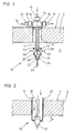
- the device shown in FIG. 1 and designated 10 serves for introducing a medium into the combustion chamber 4 of a tunnel kiln 1 and consists of a lance 11 held by means of a plate 12 in a stoke hole 3 incorporated in the ceiling 2 of the tunnel kiln 1 and a lance 11 on the latter in the combustion chamber 4 protruding end attached mixing nozzle 21.
- a throttle 13 is attached to the end of the lance 11.
- the mixing nozzle 21 consists of a cylindrical part 23 and a region 24 which tapers continuously in cross section, the inner surface 25 of which is convexly curved.
- openings 26 are machined, in the exemplary embodiment shown these are two mutually opposite bores, through which, as represented by the arrows denoted by 32, gas 31 exits through the jet 31 emerging from the throttle 13 is sucked into the combustion chamber 4.
- this mixture emerges as a bundled jet 33 from the outlet opening 22 of the mixing nozzle 21 and is burned flame-free in the combustion chamber 4.
- the lance 11 is provided with a mixing chamber 14, to which supply lines 15, 17 and 19 are connected.
- a solenoid valve 16, 18 and 20 is used, so that, for. B. alternately to be able to carry out firing with gas or atomized oil, via line 15 a combustible gas which flows through the mixing chamber 14, or this via lines 17 and 19 oil and compressed air, which are mixed in the mixing chamber 14, supplied becomes. If necessary, the lighting can be changed quickly and without any structural measures being necessary.
- the power is controlled by switching the solenoid valves 16 or 18 and 20, the switching frequency and duration of opening are proportional to the power of the mixing nozzle 21.
- the mixing nozzle 21 can also be supplied with air.
- the lance 11 is provided with a sheath 27 which is adjustable in height by the path s, so that a flow channel 28 is created.
- fresh air lower layer
- gas from the combustion chamber 4 upper layer
- a mixture of both a mixture of both
- the air can also be supplied under pressure.
- the amount of air is partially controlled by the gas flow, since the resistance in the mixing nozzle 21 is greatly reduced during the gas injection and the amount of air is considerably increased.
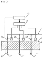
- the mixing nozzle is used to fire a tunnel furnace, it is appropriate, as shown schematically in FIG. 3, in each case a plurality of mixing nozzles 21 ', 21 ", 21"', to which the combustible gas can be controlled via a common gas supply line 15 'and also in a pulsed manner Solenoid valves 16 ' " 16", 16 "flowed in to form a group.
- a control unit 41 By means of a control unit 41, the opening time of one of the solenoid valves 16', 16" or 16 “” is set individually according to the required power distribution, while the opening frequency for the mixing nozzles is one Group is specified together by a controller 42 as a function of the temperature in the combustion chamber 4, which is measured via a thermocouple 43, via the control unit 41.
Landscapes
- Engineering & Computer Science (AREA)
- Mechanical Engineering (AREA)
- General Engineering & Computer Science (AREA)
- Chemical & Material Sciences (AREA)
- Combustion & Propulsion (AREA)
- Furnace Details (AREA)
- Chemical Vapour Deposition (AREA)
Claims (14)
Priority Applications (1)
| Application Number | Priority Date | Filing Date | Title |
|---|---|---|---|
| AT84106165T ATE23220T1 (de) | 1983-07-04 | 1984-05-30 | Vorrichtung zur impulsweisen einbringung eines gasfoermigen mediums in einem brennofen oder dgl. |
Applications Claiming Priority (2)
| Application Number | Priority Date | Filing Date | Title |
|---|---|---|---|
| DE3324050A DE3324050A1 (de) | 1983-07-04 | 1983-07-04 | Vorrichtung zur impulsweisen einbringung eines gasfoermigen mediums in einen brennofen oder dgl. |
| DE3324050 | 1983-07-04 |
Publications (2)
| Publication Number | Publication Date |
|---|---|
| EP0134907A1 EP0134907A1 (fr) | 1985-03-27 |
| EP0134907B1 true EP0134907B1 (fr) | 1986-10-29 |
Family
ID=6203098
Family Applications (1)
| Application Number | Title | Priority Date | Filing Date |
|---|---|---|---|
| EP84106165A Expired EP0134907B1 (fr) | 1983-07-04 | 1984-05-30 | Dispositif pour l'amenée d'un milieu gazeux sous forme d'impulsion dans un four de calcination, etc. |
Country Status (3)
| Country | Link |
|---|---|
| EP (1) | EP0134907B1 (fr) |
| AT (1) | ATE23220T1 (fr) |
| DE (2) | DE3324050A1 (fr) |
Families Citing this family (6)
| Publication number | Priority date | Publication date | Assignee | Title |
|---|---|---|---|---|
| DE3835360A1 (de) * | 1988-10-17 | 1990-04-19 | Keller Spezialtechnik Gmbh | Tunnelofen |
| ATE147496T1 (de) * | 1992-03-04 | 1997-01-15 | Bacher & Schmidt Gmbh | Verfahren und vorrichtung zur gasbefeuerung eines brennofens der keramischen industrie |
| DE4423221A1 (de) * | 1994-07-01 | 1996-01-04 | Lingl Anlagenbau | Wärmeübergang im Tunnelofen |
| DE4430267A1 (de) * | 1994-08-26 | 1996-02-29 | Bosch Gmbh Robert | Brenner zur flammenlosen Verbrennung eines Brenngas-Luftgemisches |
| DE10036774A1 (de) * | 2000-07-28 | 2002-02-14 | Aichelin Gmbh | Ofen und Verfahren zur thermischen Reinigung von Abgasen |
| DE102023124862A1 (de) * | 2023-09-14 | 2025-03-20 | Alexander Wilden Beteiligungen GmbH | Erwärmen und Presshärten eines Bauteils |
Family Cites Families (4)
| Publication number | Priority date | Publication date | Assignee | Title |
|---|---|---|---|---|
| DE90411C (fr) * | ||||
| US1646208A (en) * | 1926-07-07 | 1927-10-18 | American Dressler Tunnel Kilns | Tunnel kiln |
| FR1570036A (fr) * | 1968-04-25 | 1969-06-06 | ||
| DE2130072A1 (de) * | 1971-06-18 | 1972-12-21 | Andreas Haessler | Impulsumwaelzverfahren fuer Durchlaufoefen |
-
1983
- 1983-07-04 DE DE3324050A patent/DE3324050A1/de not_active Withdrawn
-
1984
- 1984-05-30 EP EP84106165A patent/EP0134907B1/fr not_active Expired
- 1984-05-30 AT AT84106165T patent/ATE23220T1/de not_active IP Right Cessation
- 1984-05-30 DE DE8484106165T patent/DE3461118D1/de not_active Expired
Also Published As
| Publication number | Publication date |
|---|---|
| DE3461118D1 (en) | 1986-12-04 |
| DE3324050A1 (de) | 1985-01-17 |
| EP0134907A1 (fr) | 1985-03-27 |
| ATE23220T1 (de) | 1986-11-15 |
Similar Documents
| Publication | Publication Date | Title |
|---|---|---|
| DE69314903T2 (de) | Verbrennungsverfahren mit thermischer Düse | |
| DE69522691T2 (de) | Brenner mit niedriger nox-produktion | |
| DE10217524A1 (de) | Brenner mit seitlichem Austritt zur flammenlosen Oxidation | |
| DE1401853B2 (fr) | ||
| DE1501802A1 (de) | Brenner | |
| EP0134907B1 (fr) | Dispositif pour l'amenée d'un milieu gazeux sous forme d'impulsion dans un four de calcination, etc. | |
| WO2022117345A1 (fr) | Dispositif et procédé d'alimentation en air de combustion et de recirculation de gaz d'échappement pour un brûleur | |
| DE1178767B (de) | Verfahren zur Beheizung von Brennoefen der Grobkeramik und Brennofen mit Vorrichtung zur Durchfuehrung dieses Verfahrens | |
| DE4113412C2 (de) | Vorrichtung zur Verbrennung von flüssigem oder gasförmigem Brennstoff für eine Feuerungsanlage | |
| AT410843B (de) | Tunnelbrennofen | |
| DE2712989C2 (de) | Zündofen zur Zündung von Sintermischungen | |
| DE4014693A1 (de) | Vorrichtung und verfahren zur versorgung eines brenners mit brenngas und sauerstoff | |
| DE352795C (de) | Verfahren zum Heizen von Schmelzoefen | |
| DE606168C (de) | Drehrohrofen | |
| EP0787947B1 (fr) | Brûleur à faible émission de NOx avec caractéristique de fonctionnement améliorée | |
| AT387456B (de) | Tunnelofen zum brennen keramischer erzeugnisse | |
| DE2254551C3 (de) | Verfahren und Einrichtung zur Sturzkühlung des Brenngutes durch Absenken der Temperatur in Tunnelöfen | |
| AT25632B (de) | Schachtofen zum Brennen von Kalk, Dolomit u. dgl. mit Generatorgasfeuerung. | |
| EP3650753A1 (fr) | Procédé et dispositif de combustion étagée sans inflammation | |
| EP0344600B1 (fr) | Procédé pour augmenter l'addition de ferraille par un préchauffage de cette ferraille dans le convertisseur | |
| EP0559144B1 (fr) | Procédé et appareil pour le chauffage au gaz d'un four à cuisson de l'industrie céramique | |
| DE585188C (de) | Regenerativofen mit gleichbleibender Flammenrichtung, dessen Arbeitsraum Gas und Luft gleichzeitig von entgegengesetzten Seiten zugefuehrt werden | |
| DE246106C (fr) | ||
| DE2306009C3 (de) | Vorrichtung zur flammlosen Verbrennung von gas- oder dampfförmigen Brennstoff-Luft-Gemischen | |
| DE440747C (de) | Verfahren und Vorrichtung zum Brennen von Portlandzement u. dgl. im Drehofen |
Legal Events
| Date | Code | Title | Description |
|---|---|---|---|
| PUAI | Public reference made under article 153(3) epc to a published international application that has entered the european phase |
Free format text: ORIGINAL CODE: 0009012 |
|
| AK | Designated contracting states |
Designated state(s): AT DE FR GB NL |
|
| 17P | Request for examination filed |
Effective date: 19850207 |
|
| 17Q | First examination report despatched |
Effective date: 19860304 |
|
| GRAA | (expected) grant |
Free format text: ORIGINAL CODE: 0009210 |
|
| AK | Designated contracting states |
Kind code of ref document: B1 Designated state(s): AT DE FR GB NL |
|
| PG25 | Lapsed in a contracting state [announced via postgrant information from national office to epo] |
Ref country code: NL Effective date: 19861029 Ref country code: FR Free format text: LAPSE BECAUSE OF NON-PAYMENT OF DUE FEES Effective date: 19861029 |
|
| REF | Corresponds to: |
Ref document number: 23220 Country of ref document: AT Date of ref document: 19861115 Kind code of ref document: T |
|
| REF | Corresponds to: |
Ref document number: 3461118 Country of ref document: DE Date of ref document: 19861204 |
|
| EN | Fr: translation not filed | ||
| PLBI | Opposition filed |
Free format text: ORIGINAL CODE: 0009260 |
|
| NLV1 | Nl: lapsed or annulled due to failure to fulfill the requirements of art. 29p and 29m of the patents act | ||
| 26 | Opposition filed |
Opponent name: C. KELLER GMBH U.CO. KG Effective date: 19870323 |
|
| RDAG | Patent revoked |
Free format text: ORIGINAL CODE: 0009271 |
|
| STAA | Information on the status of an ep patent application or granted ep patent |
Free format text: STATUS: PATENT REVOKED |
|
| GBPR | Gb: patent revoked under art. 102 of the ep convention designating the uk as contracting state | ||
| 27W | Patent revoked |
Effective date: 19880717 |