EP0135006A2 - Hygroskopische Belüftungskappe - Google Patents
Hygroskopische Belüftungskappe Download PDFInfo
- Publication number
- EP0135006A2 EP0135006A2 EP84108151A EP84108151A EP0135006A2 EP 0135006 A2 EP0135006 A2 EP 0135006A2 EP 84108151 A EP84108151 A EP 84108151A EP 84108151 A EP84108151 A EP 84108151A EP 0135006 A2 EP0135006 A2 EP 0135006A2
- Authority
- EP
- European Patent Office
- Prior art keywords
- desiccant
- standpipe
- air
- filter
- radially outer
- Prior art date
- Legal status (The legal status is an assumption and is not a legal conclusion. Google has not performed a legal analysis and makes no representation as to the accuracy of the status listed.)
- Withdrawn
Links
- 239000002274 desiccant Substances 0.000 claims abstract description 40
- 239000003208 petroleum Substances 0.000 claims abstract description 20
- 239000000428 dust Substances 0.000 claims abstract description 18
- 239000004744 fabric Substances 0.000 claims abstract description 17
- 239000002245 particle Substances 0.000 claims abstract description 6
- 239000007788 liquid Substances 0.000 claims abstract description 5
- 239000006260 foam Substances 0.000 claims description 15
- 230000003647 oxidation Effects 0.000 claims description 5
- 238000007254 oxidation reaction Methods 0.000 claims description 5
- 238000011109 contamination Methods 0.000 claims description 4
- 229920000728 polyester Polymers 0.000 claims description 3
- XLYOFNOQVPJJNP-UHFFFAOYSA-N water Substances O XLYOFNOQVPJJNP-UHFFFAOYSA-N 0.000 claims description 3
- 239000012780 transparent material Substances 0.000 claims description 2
- 230000002093 peripheral effect Effects 0.000 claims 4
- 238000005192 partition Methods 0.000 claims 1
- 239000012530 fluid Substances 0.000 abstract description 2
- 238000010276 construction Methods 0.000 description 4
- 238000001914 filtration Methods 0.000 description 3
- 239000000463 material Substances 0.000 description 3
- 238000012986 modification Methods 0.000 description 2
- 230000004048 modification Effects 0.000 description 2
- 230000000737 periodic effect Effects 0.000 description 2
- VYPSYNLAJGMNEJ-UHFFFAOYSA-N Silicium dioxide Chemical compound O=[Si]=O VYPSYNLAJGMNEJ-UHFFFAOYSA-N 0.000 description 1
- 239000003610 charcoal Substances 0.000 description 1
- 239000000356 contaminant Substances 0.000 description 1
- 230000007812 deficiency Effects 0.000 description 1
- 239000006261 foam material Substances 0.000 description 1
- 238000009434 installation Methods 0.000 description 1
- JEIPFZHSYJVQDO-UHFFFAOYSA-N iron(III) oxide Inorganic materials O=[Fe]O[Fe]=O JEIPFZHSYJVQDO-UHFFFAOYSA-N 0.000 description 1
- 238000012423 maintenance Methods 0.000 description 1
- 230000002035 prolonged effect Effects 0.000 description 1
- 239000000741 silica gel Substances 0.000 description 1
- 229910002027 silica gel Inorganic materials 0.000 description 1
Images

Classifications
-
- B—PERFORMING OPERATIONS; TRANSPORTING
- B01—PHYSICAL OR CHEMICAL PROCESSES OR APPARATUS IN GENERAL
- B01D—SEPARATION
- B01D53/00—Separation of gases or vapours; Recovering vapours of volatile solvents from gases; Chemical or biological purification of waste gases, e.g. engine exhaust gases, smoke, fumes, flue gases, aerosols
- B01D53/26—Drying gases or vapours
- B01D53/261—Drying gases or vapours by adsorption
-
- B—PERFORMING OPERATIONS; TRANSPORTING
- B01—PHYSICAL OR CHEMICAL PROCESSES OR APPARATUS IN GENERAL
- B01D—SEPARATION
- B01D46/00—Filters or filtering processes specially modified for separating dispersed particles from gases or vapours
- B01D46/30—Particle separators, e.g. dust precipitators, using loose filtering material
Definitions
- the present invention relates to a breather cap for a liquid petroleum tank and is intented to insure that the air passing into the petroleum tank is both clean and dry.
- a further problem with systems such as illustrated in the McCall patent is that the air passing into the dust filter may pass through the dust filter into the oil reservoir without passing through-the desiccant. In this way, the value of the desiccant to the system may be materially reduced.
- the hygroscopic breather cap of the invention removes dust from the air prior to passage through the desiccant.
- novel hygroscopic breather cap prevents the passage of desiccant fines into the petroleum tank.
- a further object of the present invention is to provide a novel construction for a hygroscopic breather cap in which the condition of the desiccant may be readily observed without exposing the contents of the petroleum tank or the desiccant to the atmosphere. This is accomplished by the features of claims 2 or 3.
- Still a further object of the present invention is to provide a novel construction for a hygroscopic breather cap in which the effective air input openings may be easily increased in the field --to adapt the breather cap for a particular application.
- the breather cap of the present invention may be provided with a cylindrical body 10, a bottom end cap or closure plate 12 and a removable top 14. Disposed within the body 10 is a standpipe 16 which may be connected by a suitable conventional means to a petroleum tank 18 such as an oil reservoir of an industrial machine.
- the tank 18 may be provided with a conventional male fitting and the standpipe 16 of the present invention connected thereto by means of a relatively stiff rubber or plastic sleeve 20 with sufficient resiliency to receive the standpipe 16 and the fitting of the tank 18 in an air impervious and physically supported relationship.
- the breather cap of the present invention may be internally or externally threaded to mate with a conventional threaded fitting on the tank 18.
- the standpipe 16 passes through a central aperture in the bottom of the body to a position adjacent the closed upper end thereof.
- the lower end cap may be provided with a plurality of apertures 22 open to the atmosphere and the anulus between the standpipe 16 and the body 10 defines a radially outer passageway for air passing from the bottom of the breather cap to the closed upper end thereof.
- This filter element 24 may be of any suitable conventional type but is desirably comprised of a knitted polyester fabric with good releasing characteristics when agitated or subjected to a revenue air flow. Felt may also be used, but generally is less desirable because of the tendency of particles to embed.
- the radially outer passageway may be filled along its length with any suitable conventional desiccant such as a silica gel, typically one in which the color changes, e.g. from blue to pink, as a function of the saturation of thedesiccant with moisture.
- desicants may be mixed to combine the indicating characteristics with other characteristics.
- the upper end of the standpipe 16 may be provided with a foam element 26 which serves to increase the effective surface area of the open upper end of the standpipe 16.
- This material may be of any suitable conventional material such as a 30 to 45 PPI foam with or without charcoal and serves the additional purpose of preventing the passage of desiccant fines into the standpipe 16 and thus into the tank.
- air passes upwardly through the radially outer apertures 22, through the dust filter 24, through thedesiccant 25 along the vertical length of the breather cap, and through the foam material 26 into the top of the standpipe 16.
- the air is passed successively through a dust filter, a desicant, and adesiccantfine filter before passage into the petroleum tank is permitted.
- a transparent window 15 may be provided in the top 14 of the filter so that the condition of the desiccant adjacent the open end of the standpipe 16 may be observed without removal of the filter from its operational status. In this way, the condition of the filter furtherest from the air inlet, and thus the last of the desicant to be contaminated, may be readily observed and the breather cap removed only when necessary for recharging with desicant.
- a second washer-shaped filter 28 may be provided atop the desiccant 25. It may be held securely in place by a foam member 30 which fills the cavity within the top 14.
- the functional operation of the filter-constructed as illustrated in Figure 2 may be seen in Figure 3 where air passes through the first filter 24, through the desiccant 25, through the second filter 28 into the air pervious foam member 30 located in the top 14 of the breather cap. From there, the air passes downwardly into the open top of the standpipe 16 (not shown in Figure 3) and into the petroleum tank.
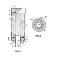
- a standpipe 32 may be used to carry a generally cylindrical body 34 by virtue of an end or closure plate 36.
- the closure plate 36 may have a cylindrical sleeve portion 38 adapted to engage the standpipe 32 in an air impervious relationship.
- the central sleeve 38 may be connected to the side walls by means of a plura - lity of spaced ribs 42. These ribs 42, as well as the sleeve 38, may be used to support a first fabric filter 44. Additional support for the filter 44 may be provided by a first air impervious foam member 46.
- the central sleeve 38 may be connected to the side walls by means of a plurality of spaced ribs 42. These ribs 42, as well as the sleeve 38, may be used to support a first fabric filter 44. Additional support for the filter 44 may be provided by a first air impervious foam member 46.
- the closure plate 36 may also be provided with a number of structurally weakened areas 40 around the periphery of the central sleeve 38 so that these areas may be readily removed in the field to selectively vary the effective air intake area of the breather cap. These areas may be of the "knock-out" type or alternative simply thin-walled so that one or more thin-walled areas may be easily removed in the field by a screwdriver or other readily available tool.
- a second washer- shaped fabric filter 48 may be placed atop the desiccant47 and held in place by a second air pervious foam member 50 which fills the removable cap 52 of the breather cap.
- air entering the apertures 40 in the closure plate 36 at the bottom of the breather cap successively passes through the first foam member 46, a first fabric filter 44, the desiccant 47, through the second fabric filter 48, and the second foam member 50 into the open top of the standpipe 32.
- the entire body 34 of the breather cap may be made of a transparent material such as a clear plastic so that the condition of the desiccant 46 may be readily observed therethrough over the entire length of the filter cap.
- the present invention significantly reduces the problems of water contaminated oil, and rust inside the petroleum tank. In addition, it provides improved particulate filtration, improved oil oxidation stability and increases oil integrity. Abrasive wear of the industrial machines is reduced as is the attendant downtime and maintenance costs. Moreover, the condition of the unit is constantly available without taking the unit out of service.
- the breather cap of the present invention provides for filtering of dust particles before the air reaches the desicant and ensures a prolonged passage of the air through the desiccant
- a second filter is provided to prevent the passage of desiccant fines into the petroleum tank.
- the construction of the breather cap is simple, thus facilitating installation and varying of the effective air intake area in the field.
- the breather cap is easily recharged with desiccant by removal of the top.
Landscapes
- Chemical & Material Sciences (AREA)
- Chemical Kinetics & Catalysis (AREA)
- Engineering & Computer Science (AREA)
- Analytical Chemistry (AREA)
- General Chemical & Material Sciences (AREA)
- Oil, Petroleum & Natural Gas (AREA)
- Drying Of Gases (AREA)
- Treatment Of Liquids With Adsorbents In General (AREA)
- Filtering Of Dispersed Particles In Gases (AREA)
Applications Claiming Priority (2)
| Application Number | Priority Date | Filing Date | Title |
|---|---|---|---|
| US06/514,459 US4504289A (en) | 1983-07-15 | 1983-07-15 | Hygroscopic breather cap |
| US514459 | 1983-07-15 |
Publications (2)
| Publication Number | Publication Date |
|---|---|
| EP0135006A2 true EP0135006A2 (de) | 1985-03-27 |
| EP0135006A3 EP0135006A3 (de) | 1987-10-07 |
Family
ID=24047244
Family Applications (1)
| Application Number | Title | Priority Date | Filing Date |
|---|---|---|---|
| EP84108151A Withdrawn EP0135006A3 (de) | 1983-07-15 | 1984-07-11 | Hygroskopische Belüftungskappe |
Country Status (8)
| Country | Link |
|---|---|
| US (1) | US4504289A (de) |
| EP (1) | EP0135006A3 (de) |
| AU (1) | AU3210184A (de) |
| CA (1) | CA1229558A (de) |
| IL (1) | IL72402A0 (de) |
| PT (1) | PT78917B (de) |
| WO (1) | WO1985000534A1 (de) |
| ZA (1) | ZA845454B (de) |
Cited By (3)
| Publication number | Priority date | Publication date | Assignee | Title |
|---|---|---|---|---|
| DE10031004B4 (de) * | 2000-06-30 | 2005-06-16 | Jochen Giebel | Vorrichtung zum Belüften von Behältern mit adsorptiv getrockneter Luft |
| DE102009049546A1 (de) | 2009-10-16 | 2011-04-21 | Hydac Filtertechnik Gmbh | Vorrichtung zum Trocknen eines Medienstroms |
| DE102010025736A1 (de) | 2010-07-01 | 2012-01-05 | Hydac Filter Systems Gmbh | Vorrichtung zum Entfeuchten eines hydraulischen Mediums |
Families Citing this family (36)
| Publication number | Priority date | Publication date | Assignee | Title |
|---|---|---|---|---|
| JPS60161623U (ja) * | 1984-04-06 | 1985-10-26 | トヨタ自動車株式会社 | 車両用燃料タンク |
| US4594082A (en) * | 1984-11-19 | 1986-06-10 | Harris Corporation | Dehydrating air-filtering apparatus |
| US4677929A (en) * | 1986-02-28 | 1987-07-07 | Harris William B | Desiccant cartridge for fuel tank vent line |
| US4694267A (en) * | 1986-08-08 | 1987-09-15 | Rockwell International Corporation | Waveguide dehydrator apparatus |
| US4689057A (en) * | 1986-08-13 | 1987-08-25 | Olin Corporation | Chemical drum dehumidifying breather |
| US4703736A (en) * | 1986-09-25 | 1987-11-03 | Chrysler Motors Corporation | Fuel vapor containment device |
| US5575833A (en) * | 1992-09-25 | 1996-11-19 | Parker-Hannifin Corporation | Refrigerant recycling system and apparatus |
| US5575832A (en) * | 1994-09-21 | 1996-11-19 | Humidtech Research, Inc. | Regenerative hygroscopic filter and method |
| US6064287A (en) * | 1997-10-28 | 2000-05-16 | Msx, Inc. | Waveguide with self-pressurizing dehydrator |
| USD438606S1 (en) | 1998-10-30 | 2001-03-06 | Fluid Protection Corporation | Contamination control breather |
| USD439644S1 (en) | 1998-10-30 | 2001-03-27 | Fluid Protection Corporation | Contamination control breather |
| US6217639B1 (en) | 1998-10-30 | 2001-04-17 | Fluid Protection Corporation | Contamination control breather |
| USD439318S1 (en) | 1998-10-30 | 2001-03-20 | Fluid Protection Corporation | Contamination control breather |
| WO2005083240A1 (en) * | 2004-02-23 | 2005-09-09 | Donaldson Company, Inc. | Crankcase ventilation filter |
| CA2585129A1 (en) * | 2004-10-25 | 2006-05-04 | Porous Media Corporation | Membrane-based reservoir dryer |
| US12172111B2 (en) | 2004-11-05 | 2024-12-24 | Donaldson Company, Inc. | Filter medium and breather filter structure |
| EP1827649B1 (de) * | 2004-11-05 | 2013-02-27 | Donaldson Company, Inc. | Filtermedium und -struktur |
| US8021457B2 (en) | 2004-11-05 | 2011-09-20 | Donaldson Company, Inc. | Filter media and structure |
| US8057567B2 (en) | 2004-11-05 | 2011-11-15 | Donaldson Company, Inc. | Filter medium and breather filter structure |
| US8177875B2 (en) * | 2005-02-04 | 2012-05-15 | Donaldson Company, Inc. | Aerosol separator; and method |
| WO2006091594A1 (en) | 2005-02-22 | 2006-08-31 | Donaldson Company, Inc. | Aerosol separator |
| WO2007019465A2 (en) * | 2005-08-08 | 2007-02-15 | Fluidtran, Inc. | Drum bung and filter apparatus |
| EP2117674A1 (de) * | 2007-02-22 | 2009-11-18 | Donaldson Company, Inc. | Filterelement und verfahren |
| WO2008103821A2 (en) * | 2007-02-23 | 2008-08-28 | Donaldson Company, Inc. | Formed filter element |
| US8499788B2 (en) * | 2008-06-03 | 2013-08-06 | Richard J. RAYMO, SR. | Dry air fuel vent breather |
| US8267681B2 (en) | 2009-01-28 | 2012-09-18 | Donaldson Company, Inc. | Method and apparatus for forming a fibrous media |
| EP2904225B1 (de) * | 2012-10-04 | 2019-09-18 | Des-Case Corporation | Trockner für ein diagnostisches beatmungsgerät |
| US11338241B2 (en) * | 2012-10-04 | 2022-05-24 | Des-Case Corporation | Diagnostic breather dryer |
| WO2015017447A1 (en) * | 2013-07-29 | 2015-02-05 | Donaldson Company, Inc. | Turbine bearing lubricant filtration system |
| CN106439138B (zh) * | 2016-10-25 | 2019-04-09 | 深圳市科兰德实业发展有限公司 | 一种恒定水蒸气分压力的恒压阀 |
| CN106382774B (zh) * | 2016-11-02 | 2022-03-04 | 珠海格力电器股份有限公司 | 汽液过滤网、换热器和空调器 |
| US10767607B2 (en) | 2017-06-05 | 2020-09-08 | Fluid Routing Solutions, LLC | Filter assembly for a fresh air filtration system, fresh air filtration system made therewith, and method of filtering fresh air |
| US10876446B2 (en) * | 2018-05-14 | 2020-12-29 | Des-Case Corporation | System and apparatus for a diagnostic breather dryer having a coupleable expansion pack |
| EP3846920B1 (de) * | 2018-09-07 | 2023-06-14 | Merck Patent GmbH | Entlüftungsfilter und reiner flüssigkeitsspeichertank |
| EP3873642B1 (de) * | 2018-11-01 | 2023-10-25 | Donaldson Company, Inc. | Filterelement mit integriertem entlüftungsfilter |
| USD1017641S1 (en) * | 2019-11-11 | 2024-03-12 | Des-Case Corporation | Breather device |
Family Cites Families (28)
| Publication number | Priority date | Publication date | Assignee | Title |
|---|---|---|---|---|
| US1866659A (en) * | 1926-08-21 | 1932-07-12 | Silica Gel Corp | Method and means for purifying the regrigerant in refrigerating systems |
| US2325657A (en) * | 1940-05-13 | 1943-08-03 | Neal B Burkness | Combined filter, dehydrator, and indicator |
| US2671528A (en) * | 1944-01-25 | 1954-03-09 | William E Gross | Air purifier |
| US2428426A (en) * | 1944-02-26 | 1947-10-07 | Lynn G Lindsay | Dehydrator attachment for tanks |
| US2603308A (en) * | 1947-02-20 | 1952-07-15 | Vertus C Barnett | Air filter and breather for fluid fuel containers |
| US2675093A (en) * | 1949-10-03 | 1954-04-13 | Arthur B Mccall | Gas or oil tank cap |
| US2758719A (en) * | 1953-01-22 | 1956-08-14 | Ansul Chemical Co | Dehydrator |
| US2852326A (en) * | 1955-06-23 | 1958-09-16 | Jr Edward B Westlake | Desiccant container |
| US3029581A (en) * | 1957-03-25 | 1962-04-17 | Robbins Aviat Inc | Desiccating apparatus |
| FR1247430A (fr) * | 1959-10-21 | 1960-12-02 | Pompes Funebres Generales | Dispositif d'absorption pour cercueils |
| US3047993A (en) * | 1960-02-03 | 1962-08-07 | Robbins Aviat Inc | Hermetically sealed cartridge with leak detection means |
| US3048958A (en) * | 1960-07-13 | 1962-08-14 | Continental Oil Co | Vacuum breaker device for tank cars |
| US3160487A (en) * | 1963-02-25 | 1964-12-08 | Novo Ind Corp | Breather cap |
| US3244314A (en) * | 1964-07-13 | 1966-04-05 | John G Fisher | Vent cap |
| US3434599A (en) * | 1967-04-28 | 1969-03-25 | Sporlan Valve Co | Filter-drier unit |
| GB1200985A (en) * | 1968-05-22 | 1970-08-05 | Perry Comb Accessories Ltd | Improvements in or relating to air filter/dryer units |
| US3546853A (en) * | 1968-08-09 | 1970-12-15 | Ralph H Claar | Covering and filtering apparatus for fuel tanks |
| US3705480A (en) * | 1970-02-06 | 1972-12-12 | Wallace M Wireman | Dehydrator for gaseous fluids |
| US3744976A (en) * | 1970-11-23 | 1973-07-10 | Grace W R & Co | Venting device |
| US3731678A (en) * | 1971-03-05 | 1973-05-08 | Phyllis Pyzel | Smoke inhalation protector |
| DE2400827C3 (de) * | 1974-01-09 | 1982-02-18 | Hasso von 4000 Düsseldorf Blücher | Filtermaterial aus offenporigem Polyurethanschaumstoff als Trägermaterial und Aktivkohle und Verfahren zu dessen Herstellung |
| US3891417A (en) * | 1974-01-28 | 1975-06-24 | King Eng Corp | Filter and sorbent cartridge |
| JPS5238680A (en) * | 1975-08-26 | 1977-03-25 | Nippon Denso Co Ltd | Filter member for air filters |
| US4064876A (en) * | 1976-01-30 | 1977-12-27 | Stanley I. Wolf | Air-pollution filter and face mask |
| DE2713963A1 (de) * | 1977-03-29 | 1978-10-12 | Wieland Carl Paul | Selektive filtermembran |
| DE7727993U1 (de) * | 1977-09-09 | 1978-02-16 | Bauer - Kompressoren Heinz Bauer, 8000 Muenchen | Filterpatrone |
| US4231768A (en) * | 1978-09-29 | 1980-11-04 | Pall Corporation | Air purification system and process |
| DE2854710C2 (de) * | 1978-12-18 | 1987-01-29 | Brown, Boveri & Cie Ag, 6800 Mannheim | Trockenpatrone |
-
1983
- 1983-07-15 US US06/514,459 patent/US4504289A/en not_active Expired - Lifetime
-
1984
- 1984-07-11 EP EP84108151A patent/EP0135006A3/de not_active Withdrawn
- 1984-07-13 CA CA000458917A patent/CA1229558A/en not_active Expired
- 1984-07-13 IL IL72402A patent/IL72402A0/xx unknown
- 1984-07-16 PT PT78917A patent/PT78917B/pt unknown
- 1984-07-16 AU AU32101/84A patent/AU3210184A/en not_active Abandoned
- 1984-07-16 WO PCT/US1984/001103 patent/WO1985000534A1/en not_active Ceased
- 1984-07-16 ZA ZA845454A patent/ZA845454B/xx unknown
Cited By (11)
| Publication number | Priority date | Publication date | Assignee | Title |
|---|---|---|---|---|
| DE10031004B4 (de) * | 2000-06-30 | 2005-06-16 | Jochen Giebel | Vorrichtung zum Belüften von Behältern mit adsorptiv getrockneter Luft |
| DE102009049546A1 (de) | 2009-10-16 | 2011-04-21 | Hydac Filtertechnik Gmbh | Vorrichtung zum Trocknen eines Medienstroms |
| WO2011044992A1 (de) | 2009-10-16 | 2011-04-21 | Hydac Filtertechnik Gmbh | Vorrichtung zum trocknen eines medienstroms |
| CN102548641A (zh) * | 2009-10-16 | 2012-07-04 | Hydac过滤技术有限公司 | 用于干燥介质流的设备 |
| CN102548641B (zh) * | 2009-10-16 | 2015-01-21 | Hydac过滤技术有限公司 | 用于干燥介质流的设备 |
| DE102010025736A1 (de) | 2010-07-01 | 2012-01-05 | Hydac Filter Systems Gmbh | Vorrichtung zum Entfeuchten eines hydraulischen Mediums |
| WO2012000584A1 (de) | 2010-07-01 | 2012-01-05 | Hydac Filter Systems Gmbh | Vorrichtung zum entfeuchten eines hydraulischen mediums |
| CN103003580A (zh) * | 2010-07-01 | 2013-03-27 | Hydac过滤系统有限公司 | 用于对液压介质除湿的设备 |
| KR20130092554A (ko) | 2010-07-01 | 2013-08-20 | 하이닥 필테르 시스템즈 게엠베하 | 유압 매체로부터 습기를 제거하기 위한 디바이스 |
| CN103003580B (zh) * | 2010-07-01 | 2016-03-23 | Hydac过滤系统有限公司 | 用于对液压介质除湿的设备 |
| US10107266B2 (en) | 2010-07-01 | 2018-10-23 | Hydac Filter Systems Gmbh | Device for removing moisture from a hydraulic medium |
Also Published As
| Publication number | Publication date |
|---|---|
| AU3210184A (en) | 1985-03-04 |
| WO1985000534A1 (en) | 1985-02-14 |
| US4504289A (en) | 1985-03-12 |
| IL72402A0 (en) | 1984-11-30 |
| CA1229558A (en) | 1987-11-24 |
| EP0135006A3 (de) | 1987-10-07 |
| ZA845454B (en) | 1985-03-27 |
| PT78917B (en) | 1986-06-18 |
| PT78917A (en) | 1984-08-01 |
Similar Documents
| Publication | Publication Date | Title |
|---|---|---|
| US4504289A (en) | Hygroscopic breather cap | |
| US4548624A (en) | Hygroscopic breather cap | |
| US5298160A (en) | Filter housing with means to prohibit fluid flow | |
| US6217639B1 (en) | Contamination control breather | |
| JPH11197426A (ja) | フィルタ排出層付属装置 | |
| US20030182757A1 (en) | Filtration arrangement of a vacuum cleaner | |
| WO1994013535A1 (en) | Fluid recovery device | |
| CA2131608A1 (en) | Apparatus and method for in situ cleaning of oil filter | |
| JPH0450844B2 (de) | ||
| RU98148U1 (ru) | Патрон для осушителя воздуха (варианты) | |
| US2840183A (en) | Apparatus for cooling and cleaning compressed air | |
| US3633750A (en) | Filter element valve means | |
| US5158691A (en) | Filter apparatus and method for filtering contaminants from machine tool coolant | |
| CA2019443A1 (en) | Oil burner pump | |
| US2788128A (en) | Liquid filter | |
| US4464260A (en) | Bracelet mounted screen filter | |
| US4387671A (en) | Air filter for a cooling system overflow container | |
| WO1996021621A1 (en) | Improved filter cartridge | |
| JPH11104409A (ja) | 液体処理用のフィルタ | |
| CA1227986A (en) | Drain trap | |
| US6878292B2 (en) | Filter device | |
| CA1186634A (en) | Liquid filter having self-retaining filtering bags | |
| GB2134807A (en) | Liquid filter | |
| EP0108043B1 (de) | Ventilmechanismus mit eingebautem Reinigungsfilter | |
| US5095553A (en) | Spill free clean out trap |
Legal Events
| Date | Code | Title | Description |
|---|---|---|---|
| PUAI | Public reference made under article 153(3) epc to a published international application that has entered the european phase |
Free format text: ORIGINAL CODE: 0009012 |
|
| AK | Designated contracting states |
Designated state(s): AT BE CH DE FR GB IT LI LU NL SE |
|
| PUAL | Search report despatched |
Free format text: ORIGINAL CODE: 0009013 |
|
| AK | Designated contracting states |
Kind code of ref document: A3 Designated state(s): AT BE CH DE FR GB IT LI LU NL SE |
|
| STAA | Information on the status of an ep patent application or granted ep patent |
Free format text: STATUS: THE APPLICATION IS DEEMED TO BE WITHDRAWN |
|
| 18D | Application deemed to be withdrawn |
Effective date: 19880408 |
|
| RIN1 | Information on inventor provided before grant (corrected) |
Inventor name: WALLER, JAMES E. |