EP0135029A1 - Dispositif d'accouplement et d'arrêt pour une palette dans un système de robot ou dans un système similaire - Google Patents
Dispositif d'accouplement et d'arrêt pour une palette dans un système de robot ou dans un système similaire Download PDFInfo
- Publication number
- EP0135029A1 EP0135029A1 EP84108450A EP84108450A EP0135029A1 EP 0135029 A1 EP0135029 A1 EP 0135029A1 EP 84108450 A EP84108450 A EP 84108450A EP 84108450 A EP84108450 A EP 84108450A EP 0135029 A1 EP0135029 A1 EP 0135029A1
- Authority
- EP
- European Patent Office
- Prior art keywords
- pallet
- stud
- docking
- socket
- robot
- Prior art date
- Legal status (The legal status is an assumption and is not a legal conclusion. Google has not performed a legal analysis and makes no representation as to the accuracy of the status listed.)
- Granted
Links
- 238000003032 molecular docking Methods 0.000 title claims abstract description 26
- 230000008878 coupling Effects 0.000 claims abstract description 4
- 238000010168 coupling process Methods 0.000 claims abstract description 4
- 238000005859 coupling reaction Methods 0.000 claims abstract description 4
- 239000000463 material Substances 0.000 description 9
- 238000010276 construction Methods 0.000 description 2
- 230000003993 interaction Effects 0.000 description 2
- 229910000831 Steel Inorganic materials 0.000 description 1
- 238000004026 adhesive bonding Methods 0.000 description 1
- XAGFODPZIPBFFR-UHFFFAOYSA-N aluminium Chemical compound [Al] XAGFODPZIPBFFR-UHFFFAOYSA-N 0.000 description 1
- 229910052782 aluminium Inorganic materials 0.000 description 1
- 239000004411 aluminium Substances 0.000 description 1
- 230000000694 effects Effects 0.000 description 1
- 238000000034 method Methods 0.000 description 1
- 230000004048 modification Effects 0.000 description 1
- 238000012986 modification Methods 0.000 description 1
- 230000036316 preload Effects 0.000 description 1
- 230000011664 signaling Effects 0.000 description 1
- 239000010959 steel Substances 0.000 description 1
Images
Classifications
-
- B—PERFORMING OPERATIONS; TRANSPORTING
- B23—MACHINE TOOLS; METAL-WORKING NOT OTHERWISE PROVIDED FOR
- B23Q—DETAILS, COMPONENTS, OR ACCESSORIES FOR MACHINE TOOLS, e.g. ARRANGEMENTS FOR COPYING OR CONTROLLING; MACHINE TOOLS IN GENERAL CHARACTERISED BY THE CONSTRUCTION OF PARTICULAR DETAILS OR COMPONENTS; COMBINATIONS OR ASSOCIATIONS OF METAL-WORKING MACHINES, NOT DIRECTED TO A PARTICULAR RESULT
- B23Q7/00—Arrangements for handling work specially combined with or arranged in, or specially adapted for use in connection with, machine tools, e.g. for conveying, loading, positioning, discharging, sorting
- B23Q7/14—Arrangements for handling work specially combined with or arranged in, or specially adapted for use in connection with, machine tools, e.g. for conveying, loading, positioning, discharging, sorting co-ordinated in production lines
- B23Q7/1426—Arrangements for handling work specially combined with or arranged in, or specially adapted for use in connection with, machine tools, e.g. for conveying, loading, positioning, discharging, sorting co-ordinated in production lines with work holders not rigidly fixed to the transport devices
Definitions
- the invention relates to a docking and fixing system for a pallet in a robot or like system.
- Modern assembly robots or like systems are able to operate without human interaction for relatively long time periods.
- Tools and/or material are to be fed into the work envelope of the robot. According to prior known technique this has been done by supplying tools and/or material on a conveyor belt continuously running through the work envelope of the robot.
- Such a system requires for example, exact positioning of the material on the conveyor belt and exact conveyor speed to make it possible for the robot gripper to find the detail needed.
- Such a conveyor belt must have a limited length material must be continuously loaded onto the conveyor belt.
- the supply of tools and/or material demands continuous human interaction.
- the pallets must be exactly positioned within the work envelope of the robot.
- the docking and fixing means according to the subject invention.
- the pallets loaded with tools and/or material are fed by the above mentioned automatic transport system into an approximate work position defined by guide rails and stop means within the work envelope of the robot. Said approximate position is sensed by sensing means and signalled to a control unit. Then, the docking and fixing means are activated by a control signal from said control unit. The docking and fixing means brings the pallet into an exactly defined work position and locks it in that position.
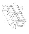
- F ig. 1 shows a perspective view of a robot system 1 provided with exchangeable work tables so called pallets 2 and 3.
- the work table area is provided with guide rails 4, 5 and 6 and stop means 7.
- the pallet can be moved into an approximate work position defined by said guide rails 4 to 6 and said stop means 7.
- the pallet is brought into an exactly defined work position and fixed (locked) in that position by the docking and fixing means according to the subject invention described below.
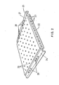
- Fig. 2 shows a perspective view of a preferred embodiment of a pallet. To meet the requirement of strength in construction and to get a very plain upper surface and at the same time keeping the weight very low the pallet is made in sandwich form.
- the pallet contains an upper plate 21 preferably an aluminium or steel plate with a well defined pattern of holes 20 therein and a lower plate 22 with corresponding holes (not shown).
- the two plates are joined together in a spaced relationship by means of square pipes 23 glued to respective plate 21 and 22.
- the pallet is provided with extruded sections 24 and 25 which are partly inserted between the plates 21 and 22 and fastened to them by means of gluing.
- the extruded sections are provided with means 26 for cooperation with docking and fixing means in accordance with the subject invention.
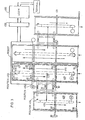
- Fig. 3 is a schematic view of a transport system for exchange of pallets in a robot system.
- the robot is of the type described above in connection with Fig. 1.
- the transport system is described in detail in the above mentioned copending Swedish patent application 8301667.5 to which reference is made.
- the transport system is devided into two parts which are mirror images of each other.
- Each part of the conveyor system consists of three transport paths.
- a first one is indicated by arrow 410 and is used for transport of a pallet from a preload position 401 to a work position 403 within the robot envelope and than back to an intermediate position 402.
- a second transport path is indicated by arrow 420 and is used for transport of the pallet from said intermediate position 402 in transport path 410 to a first position 404 of a third transport 430.
- the third transport path 430 is used to transport the pallet from said first position 404 to an output position 405 for the pallet.
- the transport paths are provided with sensing means Bl, B+, B3, B4, B5 and B6 for sensing and signalling the position of a pallet to an operation-controlling logic device 460.
- Stop means Sl, S2 and S3 with associated sensing means B7, B8 resp. B9 are also arranged along the transport paths 410 and 430.
- Docking means indicated by C2 and actuable by hydraulic means (not shown) upon a signal from the control unit 460 are arranged to cooperate with a pallet positioned in the work position 403. The position of the docking means C2 is sensed by sensing means Bll.
- the conveyor system operates automatically under program control.
- the conveyor system is via an interface 450 coupled to said operation-controlling logic device 460, which is also used for controlling the operation of the robot.
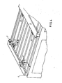
- Fig. 4 is a perspective view showing the positions of docking and fixing means 41 to 44 below the work table (pallet) area of the robot.
- the pallet is transported into an approximate work position defined by the guide rails 4 and 5 and stop means 7 by emans of a roll conveyor.
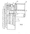
- Fig. 5 is a sectional view along line A-A of Fig. 4.
- a linear motor for example a hydralic or pneumatic motor 51 is fixedly mounted to the robot frame 8 by means of an angle bar 52.
- the movable part 53 of the motor is provided with an elongated bar 54 and a cylinder formed stud 55 for cooperation with a socket 56, which is an integral part of a stud bolt 57.
- the stud bolt 57 is adjustably fastened to the extruded section 24 of a pallet which has been brought into the approximate work position.
- the stud 55 has an upper chamfered section 58.
- the inner diameter of the socket 56 is slightly greater than the diameter of the stud 55.
- the socket 56 is provided with an inner tapered section 59 for cooperation with said chamfered section 58 of the stud 55.
- the linear motor 51 When the linear motor 51 is activated it moves bar 54 and the stud 55 upwards. During said upward movement the chamfered section 58 of the stud 55 will contact the lower inner edge of the socket 56 and cause a lateral movement of the pallet so that the stud 55 can move into the socket. At the further movement of the linear motor 51 the chamfered section 58 of the stud 55 will contact the tapered section 59 of the socket 56 with the result that the stud and the socket will be laterally exact positioned to each other. That means the pallet will be exactly positioned in the x and y coordinate directions.
- the stud will lift the pallet and press its extruded section 24 against the guide rail 4, which is fixedly mounted to the robot frame 8 in an exactly defined z coordinate position thereby exactly defining the position of the top surface of the pallet in the z coordinate direction.
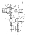
- Fig. 6 is a sectional view along line B-B of Fig. 4.
- Fig. 6 shows a sectional view of the docking and fixing means.
- the docking means 60 and 62 are fixedly mounted to the elongated bar 54 which as mentioned above is fixedly mounted to the movable part 53 of the linear motor 51.
- the extruded section 24 of the pallet is provided with corresponding docking means 61 respective 64.
- the docking means may for example consist of an electric connector 60-61 or hydralic or pneumatic connector 62-64 for supplying electrical power and/or electrical control signals respective oil or air pressure or vacuum to the devices on the pallet.
- the linear motor 51 When, as described above, the linear motor 51 is activated it moves the elongated bar 54, which is provided with the docking means 60 and 62, upwards. During said upwards movement the chamfered section 58 of the stud 55 will contact the lower inner edge of the socket 56 and cause a lateral movement of the pallet so that the stud 55 can move into the socket.
- This has also the effect that the docking means, the two parts 60 and 61 of the electric connector and the two parts 62 and - 64 of the air or oil pressure or vacuum connector, become aligned with each other.
- the two parts 60 and 61 respective 62 and 64 will be coupled together.
- One part 64 of the connector 62-63 is resiliently journalled in a housing 63 by means of a coil spring 65.
- a coil spring 65 When the lower part 62 of the connector, which is spherically formed is moved upwards it passes into the socket 66 and contacts the bushing 67 and the tapered section 68. At the further movement of the lower part 62 it presses the upper part 64 upwards against the force of the spring 65. Thus, an absolutely tight coupling is guaranteed.
Landscapes
- Engineering & Computer Science (AREA)
- Mechanical Engineering (AREA)
- Feeding Of Workpieces (AREA)
- Automatic Assembly (AREA)
- Stacking Of Articles And Auxiliary Devices (AREA)
- Automobile Manufacture Line, Endless Track Vehicle, Trailer (AREA)
- Jigs For Machine Tools (AREA)
Applications Claiming Priority (2)
| Application Number | Priority Date | Filing Date | Title |
|---|---|---|---|
| SE8304520A SE438139B (sv) | 1983-08-19 | 1983-08-19 | Docknings- och fixeringssystem for en robot eller liknande system for dockning och fixering av en pallett som har forts till en approximativ arbetsposition |
| SE8304520 | 1983-08-19 |
Publications (2)
| Publication Number | Publication Date |
|---|---|
| EP0135029A1 true EP0135029A1 (fr) | 1985-03-27 |
| EP0135029B1 EP0135029B1 (fr) | 1986-09-17 |
Family
ID=20352253
Family Applications (1)
| Application Number | Title | Priority Date | Filing Date |
|---|---|---|---|
| EP84108450A Expired EP0135029B1 (fr) | 1983-08-19 | 1984-07-18 | Dispositif d'accouplement et d'arrêt pour une palette dans un système de robot ou dans un système similaire |
Country Status (7)
| Country | Link |
|---|---|
| EP (1) | EP0135029B1 (fr) |
| JP (1) | JPS6044427A (fr) |
| DE (1) | DE3460767D1 (fr) |
| DK (1) | DK397284A (fr) |
| FI (1) | FI81981C (fr) |
| NO (1) | NO157775C (fr) |
| SE (1) | SE438139B (fr) |
Cited By (2)
| Publication number | Priority date | Publication date | Assignee | Title |
|---|---|---|---|---|
| EP0242762A3 (en) * | 1986-04-19 | 1989-12-06 | Wolfgang Mohr | Apparatus for feeding a pile of sheets to a cutting apparatus |
| EP0636448A1 (fr) * | 1993-06-29 | 1995-02-01 | Renault Automation | Unité d'indexation précise d'une palette dans le référentiel d'un poste de travail |
Families Citing this family (1)
| Publication number | Priority date | Publication date | Assignee | Title |
|---|---|---|---|---|
| CN111376032A (zh) * | 2018-12-28 | 2020-07-07 | 利星行能源(昆山)有限公司 | 移动工装及发电机的移动方法 |
Citations (3)
| Publication number | Priority date | Publication date | Assignee | Title |
|---|---|---|---|---|
| DE2638230A1 (de) * | 1976-08-25 | 1978-03-09 | Hellmut Scheffler | Foerderanlage |
| US4394897A (en) * | 1980-11-14 | 1983-07-26 | Brems John Henry | Pallet registry mechanism and transfer lift system |
| DE3212272A1 (de) * | 1982-04-02 | 1983-10-20 | Fraunhofer-Gesellschaft zur Förderung der angewandten Forschung e.V., 8000 München | Einrichtung zum automatischen transport von werkstuecken |
Family Cites Families (1)
| Publication number | Priority date | Publication date | Assignee | Title |
|---|---|---|---|---|
| JPS545592B2 (fr) * | 1972-08-15 | 1979-03-19 |
-
1983
- 1983-08-19 SE SE8304520A patent/SE438139B/sv not_active IP Right Cessation
-
1984
- 1984-06-20 JP JP59125448A patent/JPS6044427A/ja active Pending
- 1984-07-18 DE DE8484108450T patent/DE3460767D1/de not_active Expired
- 1984-07-18 EP EP84108450A patent/EP0135029B1/fr not_active Expired
- 1984-08-07 FI FI843097A patent/FI81981C/fi not_active IP Right Cessation
- 1984-08-16 NO NO843286A patent/NO157775C/no unknown
- 1984-08-17 DK DK397284A patent/DK397284A/da not_active Application Discontinuation
Patent Citations (3)
| Publication number | Priority date | Publication date | Assignee | Title |
|---|---|---|---|---|
| DE2638230A1 (de) * | 1976-08-25 | 1978-03-09 | Hellmut Scheffler | Foerderanlage |
| US4394897A (en) * | 1980-11-14 | 1983-07-26 | Brems John Henry | Pallet registry mechanism and transfer lift system |
| DE3212272A1 (de) * | 1982-04-02 | 1983-10-20 | Fraunhofer-Gesellschaft zur Förderung der angewandten Forschung e.V., 8000 München | Einrichtung zum automatischen transport von werkstuecken |
Cited By (3)
| Publication number | Priority date | Publication date | Assignee | Title |
|---|---|---|---|---|
| EP0242762A3 (en) * | 1986-04-19 | 1989-12-06 | Wolfgang Mohr | Apparatus for feeding a pile of sheets to a cutting apparatus |
| US5150647A (en) * | 1986-04-19 | 1992-09-29 | Wolfgang Mohr | Apparatus for severing stacks of sheets |
| EP0636448A1 (fr) * | 1993-06-29 | 1995-02-01 | Renault Automation | Unité d'indexation précise d'une palette dans le référentiel d'un poste de travail |
Also Published As
| Publication number | Publication date |
|---|---|
| SE438139B (sv) | 1985-04-01 |
| SE8304520D0 (sv) | 1983-08-19 |
| DK397284D0 (da) | 1984-08-17 |
| DK397284A (da) | 1985-02-20 |
| NO843286L (no) | 1985-02-20 |
| NO157775B (no) | 1988-02-08 |
| FI843097A7 (fi) | 1985-02-20 |
| FI843097A0 (fi) | 1984-08-07 |
| DE3460767D1 (en) | 1986-10-23 |
| NO157775C (no) | 1988-05-25 |
| FI81981B (fi) | 1990-09-28 |
| FI81981C (fi) | 1991-01-10 |
| JPS6044427A (ja) | 1985-03-09 |
| SE8304520L (sv) | 1985-02-20 |
| EP0135029B1 (fr) | 1986-09-17 |
Similar Documents
| Publication | Publication Date | Title |
|---|---|---|
| US4662503A (en) | Docking and locking device for a pallet in a robot or like system | |
| DE69024706D1 (de) | Steuervorrichtung für einen ebene Flächen bearbeitenden Roboter | |
| JP2577254B2 (ja) | ストリップ状工作物の供給・装着方法および装置 | |
| EP0496995B1 (fr) | Dispositif d'assemblage | |
| US4819554A (en) | Transfer and quick change system | |
| US4700472A (en) | Working apparatus provided along a workpiece conveyor | |
| US4449986A (en) | Machine for guiding numerically controlled supports for tools used in woodworking operation | |
| EP0135029B1 (fr) | Dispositif d'accouplement et d'arrêt pour une palette dans un système de robot ou dans un système similaire | |
| GB2162450B (en) | Method of moving a workpiece into a working station and apparatus for use in the method | |
| ES8301721A1 (es) | "una maquina-herramienta con una mesa de mecanizado". | |
| US4800640A (en) | Automated assembly system and method of assembly | |
| JPH082491B2 (ja) | インサ−ト部材供給装置 | |
| KR20030005612A (ko) | 부품 위치결정장치 | |
| JP2600864B2 (ja) | ワーク位置決め装置 | |
| EP0128999A1 (fr) | Palette et procédé de fabrication d'une palette | |
| JPH01284438A (ja) | 板材の位置決め装置 | |
| EP0126272B1 (fr) | Magasin pour matériaux et/ou outils pour robot ou applications analogues | |
| US6155548A (en) | Fixture for aligning and clamping a workpiece, in particular a pack of printed circuit boards, on a machine tool | |
| KR0159403B1 (ko) | 가공물 공급장치 | |
| CN210453012U (zh) | 电池保护板送料装置和电池保护板生产设备 | |
| KR950011756B1 (ko) | 중형 굴삭기 상부센터 프레임 가접트랜스퍼 시스템 | |
| KR870000018Y1 (ko) | 머시닝센터용 공작물 셋팅 스테이션 | |
| JPS63197024U (fr) | ||
| KR950001148Y1 (ko) | 자동용접 시스템의 제품자동 클램핑장치 | |
| JPS5973241A (ja) | パレツトの位置決め方法及びその装置 |
Legal Events
| Date | Code | Title | Description |
|---|---|---|---|
| PUAI | Public reference made under article 153(3) epc to a published international application that has entered the european phase |
Free format text: ORIGINAL CODE: 0009012 |
|
| 17P | Request for examination filed |
Effective date: 19841123 |
|
| AK | Designated contracting states |
Designated state(s): DE FR GB SE |
|
| GRAA | (expected) grant |
Free format text: ORIGINAL CODE: 0009210 |
|
| AK | Designated contracting states |
Kind code of ref document: B1 Designated state(s): DE FR GB SE |
|
| PG25 | Lapsed in a contracting state [announced via postgrant information from national office to epo] |
Ref country code: SE Effective date: 19860930 |
|
| REF | Corresponds to: |
Ref document number: 3460767 Country of ref document: DE Date of ref document: 19861023 |
|
| ET | Fr: translation filed | ||
| PLBE | No opposition filed within time limit |
Free format text: ORIGINAL CODE: 0009261 |
|
| STAA | Information on the status of an ep patent application or granted ep patent |
Free format text: STATUS: NO OPPOSITION FILED WITHIN TIME LIMIT |
|
| 26N | No opposition filed | ||
| PGFP | Annual fee paid to national office [announced via postgrant information from national office to epo] |
Ref country code: GB Payment date: 19920624 Year of fee payment: 9 |
|
| PGFP | Annual fee paid to national office [announced via postgrant information from national office to epo] |
Ref country code: FR Payment date: 19920630 Year of fee payment: 9 |
|
| PGFP | Annual fee paid to national office [announced via postgrant information from national office to epo] |
Ref country code: DE Payment date: 19920729 Year of fee payment: 9 |
|
| PG25 | Lapsed in a contracting state [announced via postgrant information from national office to epo] |
Ref country code: GB Effective date: 19930718 |
|
| GBPC | Gb: european patent ceased through non-payment of renewal fee |
Effective date: 19930718 |
|
| PG25 | Lapsed in a contracting state [announced via postgrant information from national office to epo] |
Ref country code: FR Effective date: 19940331 |
|
| PG25 | Lapsed in a contracting state [announced via postgrant information from national office to epo] |
Ref country code: DE Effective date: 19940401 |
|
| REG | Reference to a national code |
Ref country code: FR Ref legal event code: ST |