EP0135117A2 - Appareil pour transporter des objets - Google Patents
Appareil pour transporter des objets Download PDFInfo
- Publication number
- EP0135117A2 EP0135117A2 EP84109455A EP84109455A EP0135117A2 EP 0135117 A2 EP0135117 A2 EP 0135117A2 EP 84109455 A EP84109455 A EP 84109455A EP 84109455 A EP84109455 A EP 84109455A EP 0135117 A2 EP0135117 A2 EP 0135117A2
- Authority
- EP
- European Patent Office
- Prior art keywords
- objects
- transporter
- handler
- actuator
- operable
- Prior art date
- Legal status (The legal status is an assumption and is not a legal conclusion. Google has not performed a legal analysis and makes no representation as to the accuracy of the status listed.)
- Withdrawn
Links
- 238000012545 processing Methods 0.000 claims abstract description 144
- 238000000034 method Methods 0.000 claims description 10
- 230000008878 coupling Effects 0.000 claims 4
- 238000010168 coupling process Methods 0.000 claims 4
- 238000005859 coupling reaction Methods 0.000 claims 4
- 230000003134 recirculating effect Effects 0.000 claims 3
- 230000000284 resting effect Effects 0.000 claims 2
- 238000005096 rolling process Methods 0.000 claims 2
- 238000006073 displacement reaction Methods 0.000 claims 1
- 230000007704 transition Effects 0.000 claims 1
- 238000003780 insertion Methods 0.000 abstract description 61
- 230000037431 insertion Effects 0.000 abstract description 61
- 230000032258 transport Effects 0.000 abstract description 8
- 238000011143 downstream manufacturing Methods 0.000 abstract description 3
- 230000007246 mechanism Effects 0.000 description 24
- 238000012546 transfer Methods 0.000 description 12
- 230000000712 assembly Effects 0.000 description 6
- 238000000429 assembly Methods 0.000 description 6
- 238000013461 design Methods 0.000 description 4
- 238000004519 manufacturing process Methods 0.000 description 3
- 238000005476 soldering Methods 0.000 description 3
- 238000012423 maintenance Methods 0.000 description 2
- 239000000203 mixture Substances 0.000 description 2
- 238000011144 upstream manufacturing Methods 0.000 description 2
- 229910000831 Steel Inorganic materials 0.000 description 1
- 239000003990 capacitor Substances 0.000 description 1
- 230000006835 compression Effects 0.000 description 1
- 238000007906 compression Methods 0.000 description 1
- 238000010276 construction Methods 0.000 description 1
- 238000010586 diagram Methods 0.000 description 1
- 239000010959 steel Substances 0.000 description 1
Images




Classifications
-
- H—ELECTRICITY
- H05—ELECTRIC TECHNIQUES NOT OTHERWISE PROVIDED FOR
- H05K—PRINTED CIRCUITS; CASINGS OR CONSTRUCTIONAL DETAILS OF ELECTRIC APPARATUS; MANUFACTURE OF ASSEMBLAGES OF ELECTRICAL COMPONENTS
- H05K13/00—Apparatus or processes specially adapted for manufacturing or adjusting assemblages of electric components
- H05K13/0061—Tools for holding the circuit boards during processing; handling transport of printed circuit boards
-
- H—ELECTRICITY
- H05—ELECTRIC TECHNIQUES NOT OTHERWISE PROVIDED FOR
- H05K—PRINTED CIRCUITS; CASINGS OR CONSTRUCTIONAL DETAILS OF ELECTRIC APPARATUS; MANUFACTURE OF ASSEMBLAGES OF ELECTRICAL COMPONENTS
- H05K13/00—Apparatus or processes specially adapted for manufacturing or adjusting assemblages of electric components
- H05K13/04—Mounting of components, e.g. of leadless components
- H05K13/0495—Mounting of components, e.g. of leadless components having a plurality of work-stations
Definitions
- the present invention relates generally to apparatus for transporting uniform planar objects, and relates more particularly to an apparatus for automatically transporting printed circuit boards to and from automatic insertion machines for the automated insertion of electronic components.
- An automatic assembly system may have one insertion machine for inserting dual-in-line packaged (DIP) integrated circuits, another for inserting axial lead components such as resistors and capacitors, and a third for inserting connectors and pins.
- DIP dual-in-line packaged
- Such handling involves loading printed circuit boards into and unloading from individual insertion machines and transfering printed circuit boards between machines.
- One handling system built by Universal Instruments Corporation, was described in the May 1980 issue of Assembly Engineering magazine on pages 22-26.
- the Universal handling system utilized a batch handling technique wherein printed circuit boards were loaded into an insertion machine from a magazine of printed circuit boards and unloaded into another magazine upon completion of the insertion operation.
- Printed circuit boards were transferred between insertion machines by transferring magazines loaded with several printed circuit boards.
- the present invention automatically transfers planar and uniformly sized objects, such as printed circuit boards, between a plurality of processing means, such as automatic component insertion machines.
- the present invention is a processing system that includes transporter means for unidirectionally conveying the objects between an entrance area and an exit area, object loading means for loading objects onto the entrance area of the transporter means, a plurality of processing stations each operable for removing objects from the transporter means for processing by its associated processing means and for replacing the objects onto the transporter means after processing operations have been performed, object unloading means for unloading processed objects from the exit area of the transporter means, and control means coupled to each processing station for controlling the flow of objects through the processing system.
- the transporter means is composed of several conveyors, each associated with one processing station.
- the conveyors are arranged end-to-end so that adjacent conveyors can exchange objects to transport the objects between processing stations.
- Each conveyor is positioned above its associated processing station and has two spaced apart belts for conveying the obhects.
- Drive means for each conveyor intermittently drives the belts by a predetermined distance to transport the objects.
- Objects are loaded onto the entrance region of the transporter means by the object loading means. Objects are transported by the several conveyors to each of the processing stations and to the exit region of the transporter means. Each processing station is instructed by the control means to unload objects from its conveyor if the objects are scheduled for processing by the associated processing means. After the processing operations have been completed on an object, it is replaced on the transporter means for transport to other downstream processing stations. After objects have passed the last processing station, they are unloaded from the transporter means by the object unloading means.
- Each processing station includes the conveyor, a board depositer handler, a buffer storage unit, a fixture, processing means, an elevator, and a board retriever handler.
- the conveyor transports objects between adjacent processing stations.
- the board depositer handler provides first handler means for off-loading, from the conveyor, objects to be processed by the processing means of the processing station.
- the buffer storage unit provides buffer storage means for receiving objects from the board depositer handler, stacking them in a stack, and selectively releasing objects from the bottom of the stack. Objects are received from the buffer storage unit and positioned within the processing means by the fixture. After the processing operations for an object have been completed, the fixture moves the object to a fixture unload position where the elevator raises the object to a staging position just below the conveyor.
- the board retriever handler provides second handler means for transferring objects from the staging position to the conveyor.
- Both the board depositor handler and the board retriever handler are similar in design and function.
- Each handler includes support means for supporting it above the conveyor, moveable plate means for travel between an upper and a lower position, object grasping means for grasping, tilting, and releasing an object, and first actuator means for moving the moveable plate means between the upper and lower positions.
- the board depositor handler transfers an object from the conveyor to the buffer storage unit by first grasping and lifting the object from the belts of the conveyor, then tilting the object and lowering it through an open area between the belts, then leveling and releasing the object directly above the buffer storage unit.
- the board retriever handler transfers an object from the staging position to the conveyor by first grasping and tilting the object, then lifting the object through the open area between the belts, then leveling and lowering the object onto the belts, then releasing the object.
- the motive forces for the handlers are provided by pneumatic cylinders.
- the buffer storage unit Temporary storage of objects within a processing station is provided by the buffer storage unit. Objects enter the buffer storage unit from the above positioned board depositor handler and exit the buffer storage unit to the fixture positioned below. Within the buffer storage unit, objects are spaced apart in a vertical stack.
- the buffer storage unit includes a frame, a plurality of roller means, and release means. Each roller means has two horizontally disposed and parallel axles that are interconnected for counterroation. Star wheels, with uniformly spaced apart spokes radiating therefrom, are affixed to the axles. The axles and star wheels of the roller means are positioned such that the spokes contact two opposite edges of an object.
- the roller means supports an object when its axles are constrained not to rotate, while permitting the object to drop when its axles are free to rotate. All roller means are oriented so that they form two vertical and parallel banks of star wheels. An object entering the top of the buffer storage unit drops until it encounters a roller means that can not rotate. The release means selectively constrains the rotation of the bottom-most roller means. The presence of an object in the buffer storage unit prevents rotation of the immediately above roller means, thus spacing apart objects in the stack.
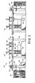
- Processing system 20 operates to transfer printed circuit boards from an input carrousel 22 to one or several processing stations 24 and 26 for the automatic insertion of components, and then to an output carrousel 28.
- an object loader 30 provides object loading means for withdrawing printed circuit boards 32 from the input carrousel 22 and for placing them upon an entrance region 34 of a transporter 36.
- Transporer 36 provides transporter means for transporting the printed circuit boards between processing stations and to an exit region 38 at the downstream end of the transporter. As printed circuit boards proceed down the transporter, the processing stations read identifying labels on the printed circuit boards.
- a system controller 40 provides control means to direct each processing station to off-load a printed circuit board if it is scheduled to have components inserted by that processing station. After components have been inserted, the printed circuit board is replaced onto the transporter for transport to other downstream processing stations. By the time the printed circuit board reaches the exit region 38, all automatically inserted components have been installed by the several processing stations.
- an object unloader 42 provides object unloading means for transferring printed circuit boards from the transporter to the output carrousel 28. Alternatively, transporter 36 could transfer the printed circuit boards directly to a conveyor feeding an automatic soldering machine or to a manual component insertion assembly operation.
- Each of the one or several processing stations 24 and 26 in processing system 20 is operable for automatically inserting components into printed circuit boards.
- a typical processing system might include one processing station for installing dual-in-line packages, another for installing axial lead components, and a third for installing pins and connectors. While two processing stations 24 and 26 are illustrated in Figure 1, it is understood that any number of processing stations could be utilized. Production requirements may dictate, for example, that three axial lead insertion machines be used in combination with two dual-in-line package insertion machines and two pin and one connector insertion machines. It is also understood that the present invention relates to an apparatus and a method for transporting planar and uniformly sized objects between processing means in general, and that objects other than printed circuit boards and processing means other than automatic component insertion are encompassed by the scope of the invention.
- Each processing station includes a conveyor 44, a board depositor handler 46, a buffer storage unit 48, a fixture 50, an automatic component insertion machine 52, an elevator 54, a staging position 56, and a board retriever handler 58.
- the processing station is illustrated in both Figures 1 and 2.
- Conveyor 44 is supported at each end thereof by support columns 60, 62, and 64, and is positioned in line with other such conveyors to form the transporter 36.
- Motor driven belts 66 provide the means for transporting the printed circuit boards 68 and 70 along the direction of travel 72.
- Board depositer handler 46 provides first handler means for off-loading, from the conveyor, printed circuit boards to be processed by insertion machine 52. To off-load a printed circuit board, the board depositer handler first grasps a printed circuit board 68 positioned on the conveyor below, then lifts and tilts the printed circuit board, then lowers it through an open area between the belts 66 of the conveyor, and then levels the printed ciruit board and releases it at a position directly above the buffer storage unit 48.
- Buffer storage unit 48 provides buffer storage means for the temporary storage of a stack 74 of printed circuit boards.
- the buffer storage unit insures an adequate supply of printed circuit boards to feed into the insertion machine 52.
- Printed circuit boards are released by the board depositer handler 46 directly above the open top of the buffer storage unit.
- Several roller assemblies 76 guide the descent of a printed circuit board. The roller assemblies also operate to space apart the printed circuit boards in the stack. Printed circuit boards from the bottom of the stack are released to the fixture 50 when the insertion machine is ready to begin inserting components into another printed circuit board.
- the design an operation of the buffer storage unit will be described in greater detail below in conjunction with Figures 10-13.
- Fixture 50 provides fixture means for receiving a printed circuit board released by the buffer storage unit, for positioning the board within the insertion machine 52 during component insertion, and for transferring the board to the elevator 54 when component insertion is completed.
- the fixture is capable of moving in two directions in the plane of the insertion machine, with its movements controlled by the insertion machine.
- the fixture positions the printed circuit board at a fixture unload position 78, where it is lifted by the elevator up to the staging position 56.
- Vertical propulsion for the elevator is provided by a pneumatic cylinder 79 located within the base of the insertion machine.
- the staging position includes means for retaining the printed circuit board until the board retriever handler 58 replaces it onto the conveyor 44.
- the board retriever handler 58 provides second handler means for transferring printed circuit boards from the staging position 56 to the conveyor 44. To do so, the board retriever handler first grasps and tilts the printed circuit board, then lifts it through the open area between the belts, then levels and lowers it onto the belts and releases it. The design and operation of the two board handlers will be described below in greater detail with reference to Figures 5-9.
- the system controller 40 which is preferably a computer, is interconnected with a loader actuator 80, an unloader sensor and actuator 82, and all processing stations 24 and 26.
- the system controller controls the flow of printed circuit boards throughout the processing system 20. Acting on a predetermined schedule, the system controller directs the loader 30, through the loader actuator 80, to transfer printed circuit boards from the input carrousel 22 to the entrance region 34 of the transporter 36.
- Transporter 36 which consists of the conveyors 44 of the several processing stations, transports the printed circuit boards along the direction of travel 72 from the entrance region to each of the processing stations, then to the exit region 38.
- the unloader sensor and actuator 82 senses the presence of a printed circuit board at the exit region, it actuates the object unloader 42 to transfer the printed circuit board to the output carrousel 28.
- the motion of the printed circuit boards is intermittent; the transporter periodically moves forward by a predetermined distance and then pauses. Loading, and unloading of printed circuit boards at the respective entrance and exit regions of the transporter, as well as off-loading and replacing of printed circuit boards at each processing station, are accomplished during the periods when the transporter is stopped.
- the system controller coordinates the motion of each conveyor 44 by controlling a transporter drive motor 84 within each processing station.
- the system controller 40 determines the routing of each printed circuit board throughout the processing system 20.
- Each individual printed circuit board may not require component insertion by each processing station.
- the system controller directs the off-loading operation of each station according to its predetermined processing schedule to ensure that each printed circuit board is processed by the proper sequence of insertion machines.
- a bar code reader 86 is employed to identify the printed circuit board 68 located beneath the board depositor handler 46. Bar code reader 86 is positioned upstream of handler 46 and is operable for reading an encoded indetifying label affixed to each printed circuit board. If board 68 is scheduled for component insertion by insertion machine 52, the system controller directs the board depositer handler through a board depositer actuator 88 to off-load the board from the transporter.
- the buffer storage unit 48 provides temporary storage of a stack 74 of printed circuit boards. If the insertion machine 52 should require maintenance or replenishment of components, the buffer storage unit may fill to its capacity. When this happens, a buffer full sensor 9V informs the system controller, which in turn adjusts the processing schedule and the flow of printed circuit boards through the processing system to compensate until that insertion machine is back on line.
- the limiting factor in processing rate is the time required for component insertion.
- the fixture 50 is positioned under the buffer storage unit 48.
- a fixture position sensor 92 so informs the system controller 40, which in turn directs the buffer storage unit, through a buffer release actuator 94, to release the bottom-most printed circuit board of the stack 74.
- the fixture is repositioned by the insertion machine for component insertion.
- the fixture moves to the fixture unload position 78.
- the system controller directs an elevator actuator 96 to activate the elevator to transfer the printed circuit board to the staging position 56.
- the printed circuit board is replaced onto the transporter during a period when the transporter is stopped and when no printed circuit board is on the transporter below the board retriever handler 58.
- the system controller 40 directs a board retriever actuator 98 to activate the board retriever handler to transfer the board from the staging position to the transporter.
- Two side rails 10V and 102 are parallel and horizontal and are spaced apart by a distance 104 that is just slightly greater than the width of printed circuit board 68.
- Two spaced apart belts 66 and 106 contact the printed circuit board beneath its two longitudinal edges 108 and 110 and provide the means for transporting the board.
- Each belt forms a continuous loop between two sprockets 112 and 114. Perforations in the belts and cogs in the sprockets interlock so that no slipage can occur therebetween.
- Idler rollers 116 and 118 are rotateably mounted to the side rails and act to support the belts and printed circuit boards in the region between the sprockets.
- sprockets of the two belts are interconnected at each end by two shafts 120 and 122 and rotate in unison.
- Mounting blocks 124 and 126 provide means for rotateably mounting sprockets 112 and 114 to the side rails.
- a drive motor 128 provides drive means through belt 130 and sprocket 132 for driving belts 68 and 106.
- Sprocket 132 is affixed to shaft 122, as is sprocket 114 for belt 66 and a sprocket (not shown) for belt 106.
- drive motor 128 When the drive motor 128 is on, it rotates sprocket 132 and shaft 122, which in turn drives both of the belts.
- drive motor 128 is a stepper motor so as to provide distance sensing and control means for accurately advancing the belts by the predetermined distance during each transporter advance cycle.
- Conveyor 44 advantageously has an open area 134 between the two belts 66 and 106. This open area provides clearance between the belts to allow the board depositor handler 46 to off-load printed circuit boards from the conveyor 44 to the buffer storage unit 48 directly below and to allow the board retriever handler 58 to transfer boards from the staging position to the conveyor. Such vertical movement of the printed circuit boards is advantageous in simplifying the handler mechanisms.
- Adjacent conveyours are interconnected at the ends of their respective side rails 102 and 136. Plates 138 and 140 are fastened to two adjacent side rails and are secured by fasteners 142. Lateral plates 144 and 146 are fastened to the underside of the side rails and act to space the side rails apart by distance 104.
- the gap between the belts of an upstream conveyor and a downstream conveyor is small in comparison to the length of the printed circuit board, so that the boards are easily transferred from one conveyor to another.
- All of the printed circuit boards have uniform outside dimensions to facilitate board handling. All of the circuitry and components of the finished printed circuit board are located within the area defined by slots 148. After component insertion and soldering has been completed, the tabs 150 between the slots 148 are trimmed away to yield the finished printed circuit board. This permits flexibility in final board size, while providing a standard board size during processing. Although a single finished printed circuit board is illustrated within board 68 in Figure 4, several finished boards of various shapes could be accomodated. Included in the area between the slots and the edges of the printed circuit board are alignment holes 152 and 154 for alignment of the board on the fixture 50 and a bar code label 156 for board identification.
- the two board handlers, board depositor handler 46 and board retriever handler 58, are identical in design and construction.
- One embodiment of the board handlers is illustrated in Figure 5.
- the board handler generally includes a support plate 158, upper and lower moveable plates 160 and 162, two object grasping mechanisms 164 and 166 and a first pneumatic cylinder 168.
- Support plate 158 is a generally rectangular shaped plate that provides support means for supporting the board handler above the conveyor.
- Two support posts 170 and 172 support one end of the support plate above side rail 100, and two additional support posts 174 and 176 support the other end of the support plate above side rail 102.
- the four support posts retain the support plate in a fixed horizontal orientation above the conveyor.
- Support plate 158 has several areas 178 removed to reduce weight.
- the first pneumatic cylinder 168 is disposed vertically with the rod end of the cylinder fastened to the center of support plate 158 and with the cylinder protruding upward and the rod protruding downward.
- the upper and lower moveable plates 160 and 162 provide moveable plate means for vertical travel'to raise and lower a printed circuit board.
- Moveable plates 160 and 162 are generally rectangular in shape and have areas 180 and 182 removed to reduce weight.
- Two vertical guide shafts 184 and 186 are fastened at 188 and 190 to upper plate 160 and to lower plate 162 to join the two plates together.
- Guide shafts 184 and 186 are slideably coupled to the support plate 158 with two bushings 192 and 194, and act to guide the vertical movement of moveable plates 160 and 162.
- Guidance is also provided by the first pneumatic cylinder 168.
- Three guide wheels 196 and 198 are disposed on the upper plate 160 and rotate about horizontal axes defined by axles 200 and 202 attached to the upper plate.
- the guide wheels contact the outer surface of cylinder 168 to guide the upper plate as it moves up and down.
- the rod of the first pneumatic cylinder provides a first actuator rod 204 that extends downwardly from the cylinder and is attached to the lower plate 162.
- first actuator rod When the first actuator rod is retracted, the moveable plates are raised to their upper position, as illustrated in Figure 5.
- the first actuator rod When the first actuator rod is extended, the moveable plates are lowered to their lower position.
- guide shafts 184 and 186, bushings 192 and 194, cylinder 168, and guide wheels 196 and 198 act to keep the upper and lower moveable plates in a spaced apart and horizontal orientation.
- the two object grasping mechanisms 164 and 166 provide means for grasping, tilting, and releasing a printed circuit board.
- the motive force for the object grasping mechanisms are provided by second and third pneumatic cylinders 206 and 208. Cylinders 206 and 208 are oriented vertically and are fastened at one end to the underside of the upper plate 160. Second and third actuator rods 210 and 212 of cylinders 206 and 208, respectively, protrude vertically downward and pass through bushings 214 and 216 in the lower plate 162.
- the lower ends of actuator rods 210 and 212 have lift pins 218 and 220 affixed thereto, Lift pins 218 and 220 are short and cylindrical in shape and are oriented horizontally.
- a clamping bracket 222 is positioned proximate actuator rod 210 between lower plate 162 and lift pin 218.
- Clamping bracket 222 has a flange 224 with a slot 226 therein, and is positioned such that actuator rod 10 passes through the slot.
- a Compression spring 228 is disposed on actuator rod 210 between lower plate 162 and flange 224.
- a pivot lever 230 joins the upper end of the clamping bracket to the lower plate. Pivot lever 230 is coupled to the underside of the lower plate at pivot 232 (see Figure 6a) and to the upper end of the clamping bracket at pivot 234.
- a similar clamping bracket, spring, and pivot lever are provided at actuator rod 212.
- the second and third pneumatic cylinders 206 and 208 are operable for rotating, as well as extending and retracing, the second and third actuator rods 210 and 212.
- Actuator rods 210 and 212 rotate between two positions: a release position as one shown in Figure 5 wherein the two lift pins 218 and 220 are parallel and point transversely to the direction of travel 72, and a grasping position where the two lift pins point toward each other and are parallel to the direction of travel.
- the distance between the second and third actuator rods 210 and 212 is just slightly greater than the length of the printed circuit board.
- actuator rods 210 and 212 can be extended and retracted without contacting the printed circuit board.
- the lift pins are in the grasping position, the lift pins are spaced apart by a distance that is less than the lenght of the printed circuit board, and, accordingly, contact the printed circuit board.
- FIGS 6a-6e The operation of the board depositer handler 46 is illustrated in Figures 6a-6e.
- all three actuator rods 204, 210 and 212 are retracted to raise the handler above the conveyor 44 to provide clearance for the passage of printed circuit board 68.
- Lift pins 218 and 220 are in the release position, pointing transversely to the direction of tranvel.
- the second and third actuator rods 210 and 212 are retracted, lift pins 218 and 220 lift the flange 224 of clamping bracket 222. Since the upper end of clamping bracket 222 is pivotably attached to pivot lever 230, lifting the clamping bracket causes it to tilt to the position shown.
- the board depositor handler remains in this position until directed by the board depositor actuator 88 to off-load a printed circuit board positioned directly below.
- the board depositor handler 46 has begun to off-load a printed circuit board 68.
- the second and third actuator rods 210 and 212 are extended.
- Springs 228 lower the clamping brackets as actuator rods 210 and 212 extend.
- the underside of clamping brackets 222 contact the top of the printed circuit board along its two lateral sides.
- the lift pins and the lower portions of actuator rods 210 and 212 extend into the open area between belts 66 and 106 and below the printed circuit board.
- the lift pins are rotated to face each other in the grasping position, and actuator rods 210 and 212 are raised.
- the lift pins contact the underside of the printed circuit board and lock it against the flanges 224 of the clamping brackets 222. As the lift pins raise the printed circuit board and clamping brackets, to pivot levers cause the clamping brackets and board to tilt to the position shown in Figure 6c.
- the first pneumatic cylinder 168 extends the first actuator rod 204. This action lowers the moveable plates 160 and 162, as well as the grasping mechanisms 164 and 166 and the printed circuit board 68. Since the printed circuit board is tilted, there is adequate clearance between the belts 66 and 106 of the conveyor to permit the board to pass.
- the handler When the first actuator rod is fully extended, the handler is in the position illustrated in Figure 6d. Then, the second and third actuator rods 210 and 212 are extended to level the printed circuit board and place it upon the uppermost roller assembly of the buffer storage unit, as illustrated in Figure 6e.
- the board depositor handler releases the board.
- the printed circuit board 68 is grasped between the lift pins 218 and 220 and the clamping brackets 222 and 236 when the lift pins are at the grasping position.
- the second and third actuator rods 210 and 212 are rotated to move the lift pins to the release position shown in Figure 7b. This permits the printed circuit board to descent to the top of the stack of boards in the buffer storage unit 48.
- the handler retracts the three actuator rods 204, 210, and 212 to return to the position shown in Figure 6a.
- the board retriever handler 58 operates in a similar fashion, but in a reverse sequence of steps.
- the board retriever handler first extends its three actuator rods, with its lift pins in the release position. The actuator rods are extended until the clamping brackets contact the printed circuit board and the lift pins are below the board. Then the second and third actuator rods are rotated to bring the lift pins to the grasping position. Next, the second and third actuator rods are retracted to tilt the printed circuit board to the position shown in Figure 6d. The first actuator rod is then retracted to lift the printed circuit board through the open area between the belts of the conveyor.
- the second and third actuator rods extend to level and place the printed circuit board onto the belts.
- the second and third actuator rods are then rotated to bring the lift pins to the release position, releasing their grasp of the printed circuit board.
- the second and third actuator rods are retracted to lift the clamping brackets and lift pins above the conveyor.
- Board handler 238 differs from the above described board handler in its support structure and method of lifting the printed circuit board from the conveyor. Instead of fixedly mounting the support plate 239 to support posts 170, 172, 174, and 176, board handler 238 has the support plate mounted to four pneumatic cylinders 240, 242, 244 and 246. These cylinders are operable for raising and lowering the support plate of board handler 238, while keeping the support plate horizontal. Board handler 238 also has first, second and third pneumatic cylinders 248, 250, and 252 that operate in a fashion similar to cylinders 168, 206, and 208.
- Figures 9a-9e illustrate the operation of board handler 238.
- cylinder 248 When the conveyor belts are moving, cylinder 248 is retracted and cylinders 240, 242, 246, 250, and 252 are extended. This keeps the flange of the clamping bracket at a horizontal orientation, as shown in Figure 9a.
- cylinders 240, 242, 244 and 246 retract to bring the clamping brackets into contact with the board. The lift pins are then moved to their clamping position under the printed circuit board, and cylinders 250 and 252 retract to tilt the board and cylinders 240, 242, 244 and 246 extend to lift the board from the conveyor.
- board handler 238 is the same as that of board handler 46.
- Cylinder 248 extends to lower the printed circuit board through the open area between the belts of the conveyor. Then cylinders 250 and 252 extend to level the printed circuit board and to place it on the uppermost roller assembly of the buffer storage unit 48. Then the lift pins are moved to the release position to release the printed circuit board. To return board handler 238 to its starting position, cylinder 248 retracts to lift the moveable plates and grasping mechanisms above the conveyor.
- cylinder 250 and 252 need by cycled only once during each off-load sequence, instead of twice as with board handler 46.
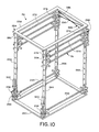
- the buffer storage unit 48 illustrated in Figure 10 is positioned directly below the board depositer handler 46 and provides temporary storage of a stack 74 of printed circuit boards. It is composed of a frame 254, several roller assemblies 76, and a release mechanism 256.
- Frame 254 is a rectangular prism in shape and has a top frame 258 and a bottom frame 260 joined by four upright members 262, 264, 266, and 268.
- the frame is preferably composed of steel bars that are welded or otherwise fastened to form a rigid structure.
- Frame 254 is attached to the side rails 100 and 102 of the conveyor 44.
- Each of the roller assemblies includes two axles 270 and 272, four star wheels 274, 276, 278, and 280 attached to the ends of the two axles, and a belt mechanism 282 to couple the rotation of the two axles.
- the two axles are hexagonal in cross-section and have rounded ends that rotate in corresponding mounting holes 284 in the upright members 262, 264, 266, and 268.
- Axles 270 and 272 are parallel and horizontal and are spaced apart by a distance slightly greater than the width of the printed circuit boards.
- Two star wheels are attached to each axle just inside the upright members of the frame. Each star wheel has six equally spaced spokes radiating outwardly from the axle. The spokes are utilized to support the printed circuit boards of the stack as will be described below.
- the axles protrude past the upright member and have sprockets 286 and 288 affixed thereto. Between and in engagement with the sprockets is disposed a toothed belt 290.
- Belt 290 forms a figure eight which interconnects the rotations of the two axles so that the axles always counterrotate by an equal amount.
- roller assemblies are mounted on the frame to provide means for guiding the descent of printed circuit boards and for spacing apart the boards in the stack 74.
- the two axles of each roller assembly are mounted between upright members 264 and 268 and between members 262 and 266. All axles are oriented horizontally and are uniformly spaced apart.
- the axles 292 and 294 of the bottom-most roller assembly are connected to the release mechanism 256.
- Release mechanism 256 has two release cam mechanisms 296 and 298, each coupled to axles 292 and 204.
- Pneumatic cylinders 300 and 302 provide release actuator means to operate the release mechanism 256.
- the purpose of the release mechanism is to rotate axles 202 and 204 by one-sixth of a revolution upon the receipt of a release command from the control system 40.
- Figure 11 illustrates the components within the release cam mechanism 298.
- Inner and outer plates 304 and 306 are joined together with screw fasteners 308 to form a release frame.
- Two slots 310 and 312 provide clearance between plates 304 and 306 and axle 294.
- Between the plates are mounted a three sided cam 314 and two cam rollers 316 and 318.
- the three sided cam 314 is mounted on the end of axle 294 and is locked in place with pin 320.
- Cam rollers 316 and 318 mount on and are rotatable about axles 322 and 324.
- Axles 322 and 324 are mounted at each end thereof into holes 326, 328, 330 and 332 in the inner and outer plates.
- An actuator rod 334 of cylinder 300 has a threaded lower end which is screwed into a corresponding threaded hole 336 in the top of the inner plate 304.
- Figures 12a and 12b illustrate the operation of the release mechanism.
- the actuator rod 334 is raised by cylinder 302.
- the cam release mechanism 298 also raises.
- Cam roller 316 then contacts a surface of cam 314 and rotates it in direction 338 to the position shown in Figure 12b. This rotates the attached axle 294 clockwise by one-sixth of a revolution.
- cylinder 300 lowers rod 334 and mechanism 298 to bring cam roller 318 into contact with cam 314, causing another clockwise rotation 340 of one-sixth of a revolution.
- the board depositor handler 46 places a printed circuit board 68 onto the star wheels 276 and 278 of the upper-most roller assembly. Due to the weight of board 68, star wheel 278 and axle 272 will rotate clockwise and star wheel 276 and axle 270 will rotate counterclockwise, allowing the board to descend. Assuming that the buffer storage unit is initally empty, board 68 will descend until it reaches the bottom-most roller assembly at 342. Since the release mechanism 256 prevents the bottom-most roller assembly from rotating, the board stays at position 342. The next printed circuit board to be off-loaded from the conveyor and placed in the top of the buffer storage unit will descend to position 344.
- Star wheels 346 and 348 are prevented from turning due to the presence of a printed circuit board at 342, and thus support the board at position 344. In this fashion, the star wheels of the buffer storage unit act to space apart the printed circuit boards of the stack. Spaces between the printed circuit boards are required to provide clearance for components that are inserted into the boards.
- the roller assemblies are spaced apart vertically by distance 350 as determined by the dimensions of the star wheels and the thickness of the printed circuit boards.
- the first actuation of the release mechanism moves the first loaded printed circuit board to position 356. All sucessive actuations of the release mechanism drops the bottom-most printed circuit board to the fixture below and moves the next higher board from position 342 to position 356. During each actuation, as the bottom-most printed circuit board is released, all boards positioned above move down by one position.
- the buffer storage unit 48 thus serves as a first-in-first-out buffer.
- Fixture 50 is positioned below the buffer storage unit 48 when a printed circuit board is released.
- the fixture serves to receive the board from the buffer storage unit, to align the board with respect to alignment pins 358 on the fixture, to position the board under the direction of the insertion machine 52 during component insertion, and to move the board to the fixture unload position 78 when component insertion is finished.
- the fixture includes two clamping shafts 360 and 362, that are pivotably mounted, several clamping cams 364 and 366 fixedly mounted to each clamping shaft, a spring 368 to bias the clamping cams toward a clamped position, and a wire 370 to open the clamping cams to a released position when the fixture is either under the buffer storage unit or at the fixture unload position.
- the clamping cams have support surfaces 372 and 374 for supporting a printed circuit board 376 in the fixture.
- fingers 378 and 380 act to hold board 376 against the support surfaces of the clamping cams.
- the fingers are pivoted back out of the way and do not contact the board.
- Support surfaces 3 72 and 374 are shaped such that board 376 is at a more elevated position when the clamping cams are at the released position than at the clamped position.
- the fixture 50 aligns the printed circuit board 376 with respect to the fixture when the clamping cams move from the released position to the clamped position.
- Alignment pin 358 has a conical portion 382 that enters alignment hole 154 in the board when the board is released by the buffer storage unit. The conical shape of the top of alignment pin 358 compenstates for misalignment between the buffer storage unit and the fixture. When the clamping cams move to the clamped position, the board is lowered onto the cylindrical portion of the alignment pin to provide precise alignment.
- Spring 368 and wire 370 move the clamping cams 364 and 366 between the released and clamping positions.
- Spring 368 is disposed in tension between pin 384 on clamping cam 364 and pin 386 on clamping cam 366. Since pins 384 are positioned above the clamping shafts 360 and 362, the spring tends to move the clamping cams toward the clamped position.
- Wire 370 is disposed between pin 388 on clamping cam 364 and pin 390 on clamping cam 366. Since pins 388 and 390 are positioned below the clamping shafts, tension on the wire tends to counteract the tension in the spring and move the clamping cams toward the released position.
- a fitting 392 attaches the center of wire 370 to one end of a lever 394, as shown in Figure 15.
- the center 396 of lever 394 is pivotably attached to the fixture, and the other end of the lever is attached to one end of a tether 398.
- the other end of tether 398 is fixedly attached at 400 to the insertion machine 52.
- the length of tether 398 and its attachment point are selected so as to provide sufficient tension in wire 370 to move the clamping cams to the released position when the fixture is under the buffer storage unit or at the fixture unload position.
- the tether loosens to allow spring 368 to move the clamping cams to the clamped position to align and clamp the printed circuit board.
- tension in the tether causes the clamping cams to pivot to the released position to release the printed circuit board.
Landscapes
- Engineering & Computer Science (AREA)
- Manufacturing & Machinery (AREA)
- Microelectronics & Electronic Packaging (AREA)
- De-Stacking Of Articles (AREA)
- Supply And Installment Of Electrical Components (AREA)
Applications Claiming Priority (2)
| Application Number | Priority Date | Filing Date | Title |
|---|---|---|---|
| US52097283A | 1983-08-08 | 1983-08-08 | |
| US520972 | 1983-08-08 |
Publications (2)
| Publication Number | Publication Date |
|---|---|
| EP0135117A2 true EP0135117A2 (fr) | 1985-03-27 |
| EP0135117A3 EP0135117A3 (fr) | 1986-04-30 |
Family
ID=24074809
Family Applications (1)
| Application Number | Title | Priority Date | Filing Date |
|---|---|---|---|
| EP84109455A Withdrawn EP0135117A3 (fr) | 1983-08-08 | 1984-08-08 | Appareil pour transporter des objets |
Country Status (1)
| Country | Link |
|---|---|
| EP (1) | EP0135117A3 (fr) |
Cited By (7)
| Publication number | Priority date | Publication date | Assignee | Title |
|---|---|---|---|---|
| EP0165561A3 (en) * | 1984-06-16 | 1987-08-05 | E.I. Du Pont De Nemours And Company | Device for the treatment of flat plates |
| WO1991011093A1 (fr) * | 1990-01-12 | 1991-07-25 | Ats Automation Tooling Systems Inc. | Systeme de montage de composants sur plaquettes de circuits imprimes |
| US7156308B2 (en) | 2001-12-17 | 2007-01-02 | International Barcode Corporation | Double-sided bar code doubling as a single bar code |
| CN109019016A (zh) * | 2018-07-23 | 2018-12-18 | 深圳市兆方智能科技有限公司 | 曝光机的自动上下料机器及曝光系统 |
| CN111832324A (zh) * | 2019-04-17 | 2020-10-27 | 深圳长城开发科技股份有限公司 | 用于smt生产线的在线自动扫描条码方法和系统 |
| CN115623702A (zh) * | 2022-10-28 | 2023-01-17 | 深圳市赛姆烯金科技有限公司 | 升降浸入式生产装置和电路板生产设备及其系统和方法 |
| CN118495001A (zh) * | 2023-11-30 | 2024-08-16 | 永天机械设备制造(深圳)有限公司 | 一种先进先出暂存设备 |
Families Citing this family (1)
| Publication number | Priority date | Publication date | Assignee | Title |
|---|---|---|---|---|
| US20030080191A1 (en) | 2001-10-26 | 2003-05-01 | Allen Lubow | Method and apparatus for applying bar code information to products during production |
Family Cites Families (1)
| Publication number | Priority date | Publication date | Assignee | Title |
|---|---|---|---|---|
| US4202092A (en) * | 1976-09-17 | 1980-05-13 | Matsushita Electric Industrial Co., Ltd. | Automatic part insertion machine |
-
1984
- 1984-08-08 EP EP84109455A patent/EP0135117A3/fr not_active Withdrawn
Cited By (9)
| Publication number | Priority date | Publication date | Assignee | Title |
|---|---|---|---|---|
| EP0165561A3 (en) * | 1984-06-16 | 1987-08-05 | E.I. Du Pont De Nemours And Company | Device for the treatment of flat plates |
| WO1991011093A1 (fr) * | 1990-01-12 | 1991-07-25 | Ats Automation Tooling Systems Inc. | Systeme de montage de composants sur plaquettes de circuits imprimes |
| US7156308B2 (en) | 2001-12-17 | 2007-01-02 | International Barcode Corporation | Double-sided bar code doubling as a single bar code |
| CN109019016A (zh) * | 2018-07-23 | 2018-12-18 | 深圳市兆方智能科技有限公司 | 曝光机的自动上下料机器及曝光系统 |
| CN109019016B (zh) * | 2018-07-23 | 2023-11-10 | 深圳市兆方智能科技有限公司 | 曝光机的自动上下料机器及曝光系统 |
| CN111832324A (zh) * | 2019-04-17 | 2020-10-27 | 深圳长城开发科技股份有限公司 | 用于smt生产线的在线自动扫描条码方法和系统 |
| CN111832324B (zh) * | 2019-04-17 | 2024-01-30 | 深圳长城开发科技股份有限公司 | 用于smt生产线的在线自动扫描条码方法和系统 |
| CN115623702A (zh) * | 2022-10-28 | 2023-01-17 | 深圳市赛姆烯金科技有限公司 | 升降浸入式生产装置和电路板生产设备及其系统和方法 |
| CN118495001A (zh) * | 2023-11-30 | 2024-08-16 | 永天机械设备制造(深圳)有限公司 | 一种先进先出暂存设备 |
Also Published As
| Publication number | Publication date |
|---|---|
| EP0135117A3 (fr) | 1986-04-30 |
Similar Documents
| Publication | Publication Date | Title |
|---|---|---|
| US8322282B2 (en) | Apparatus and process for transporting lithographic plates to a press cylinder | |
| KR100245452B1 (ko) | 기판 이송장치 및 방법 | |
| US5458226A (en) | Rotatable apparatus for transformer core plates | |
| KR101132424B1 (ko) | 기판 반송 시스템 | |
| JP3386960B2 (ja) | 板材の積載方法及びその積載装置 | |
| US4712963A (en) | Apparatus for soldering printed circuit boards | |
| US4423815A (en) | Component sorting apparatus | |
| KR101215591B1 (ko) | 기판 반송 시스템 | |
| CN221274199U (zh) | 料盘输送线及印字装置 | |
| WO1993014008A1 (fr) | Dispositif de triage vertical a deplacement progressif dans deux directions equipe de convoyeurs de stockage intermediaire | |
| JPH11309419A (ja) | Ngストッカ装置 | |
| JPH08175650A (ja) | 搬送物品の仕分け装置 | |
| JP3370137B2 (ja) | マガジン収納装置 | |
| JPS62167138A (ja) | シ−ト材自動供給装置 | |
| JP2543741B2 (ja) | マガジン移送装置 | |
| JPH042485B2 (fr) | ||
| JPH0751798Y2 (ja) | 搬送装置 | |
| JP2967606B2 (ja) | 凝集パターン判定用プレート送り出し装置 | |
| CN117566352A (zh) | 料盘移载系统 | |
| JPH05186014A (ja) | 基板搬送装置および基板搬送方法 | |
| JP2544024B2 (ja) | 作物の選別用搬送装置 | |
| JP2544023B2 (ja) | 作物の選別用搬送装置 | |
| WO2007107823A1 (fr) | Machine lineaire et procede pour traiter des objets portables | |
| JPS6361251B2 (fr) | ||
| CN121467948A (zh) | 一种新型bga元件自动化激光打标机及其打标工艺 |
Legal Events
| Date | Code | Title | Description |
|---|---|---|---|
| PUAI | Public reference made under article 153(3) epc to a published international application that has entered the european phase |
Free format text: ORIGINAL CODE: 0009012 |
|
| AK | Designated contracting states |
Designated state(s): DE FR GB NL |
|
| PUAL | Search report despatched |
Free format text: ORIGINAL CODE: 0009013 |
|
| AK | Designated contracting states |
Kind code of ref document: A3 Designated state(s): DE FR GB NL |
|
| RHK1 | Main classification (correction) |
Ipc: H05K 13/04 |
|
| STAA | Information on the status of an ep patent application or granted ep patent |
Free format text: STATUS: THE APPLICATION IS DEEMED TO BE WITHDRAWN |
|
| 18D | Application deemed to be withdrawn |
Effective date: 19861231 |
|
| RIN1 | Information on inventor provided before grant (corrected) |
Inventor name: SOELLER, RICHARD |