EP0135122A2 - Connecteur de câble et méthode d'accouplement de câble plat à plusieurs fils - Google Patents
Connecteur de câble et méthode d'accouplement de câble plat à plusieurs fils Download PDFInfo
- Publication number
- EP0135122A2 EP0135122A2 EP84109521A EP84109521A EP0135122A2 EP 0135122 A2 EP0135122 A2 EP 0135122A2 EP 84109521 A EP84109521 A EP 84109521A EP 84109521 A EP84109521 A EP 84109521A EP 0135122 A2 EP0135122 A2 EP 0135122A2
- Authority
- EP
- European Patent Office
- Prior art keywords
- cable
- shield
- connector
- insulating jacket
- secured
- Prior art date
- Legal status (The legal status is an assumption and is not a legal conclusion. Google has not performed a legal analysis and makes no representation as to the accuracy of the status listed.)
- Withdrawn
Links
- 238000000034 method Methods 0.000 title description 2
- 230000008878 coupling Effects 0.000 title 1
- 238000010168 coupling process Methods 0.000 title 1
- 238000005859 coupling reaction Methods 0.000 title 1
- 239000004020 conductor Substances 0.000 claims abstract description 6
- 229910052751 metal Inorganic materials 0.000 claims abstract description 5
- 239000002184 metal Substances 0.000 claims abstract description 5
- RYGMFSIKBFXOCR-UHFFFAOYSA-N Copper Chemical compound [Cu] RYGMFSIKBFXOCR-UHFFFAOYSA-N 0.000 description 2
- 229910052782 aluminium Inorganic materials 0.000 description 2
- XAGFODPZIPBFFR-UHFFFAOYSA-N aluminium Chemical compound [Al] XAGFODPZIPBFFR-UHFFFAOYSA-N 0.000 description 2
- 230000005684 electric field Effects 0.000 description 2
- 229910000831 Steel Inorganic materials 0.000 description 1
- 229910052802 copper Inorganic materials 0.000 description 1
- 239000010949 copper Substances 0.000 description 1
- 239000011889 copper foil Substances 0.000 description 1
- 230000005686 electrostatic field Effects 0.000 description 1
- 238000009413 insulation Methods 0.000 description 1
- 239000011159 matrix material Substances 0.000 description 1
- 239000010959 steel Substances 0.000 description 1
- 210000003813 thumb Anatomy 0.000 description 1
Images
Classifications
-
- H—ELECTRICITY
- H01—ELECTRIC ELEMENTS
- H01R—ELECTRICALLY-CONDUCTIVE CONNECTIONS; STRUCTURAL ASSOCIATIONS OF A PLURALITY OF MUTUALLY-INSULATED ELECTRICAL CONNECTING ELEMENTS; COUPLING DEVICES; CURRENT COLLECTORS
- H01R12/00—Structural associations of a plurality of mutually-insulated electrical connecting elements, specially adapted for printed circuits, e.g. printed circuit boards [PCB], flat or ribbon cables, or like generally planar structures, e.g. terminal strips, terminal blocks; Coupling devices specially adapted for printed circuits, flat or ribbon cables, or like generally planar structures; Terminals specially adapted for contact with, or insertion into, printed circuits, flat or ribbon cables, or like generally planar structures
- H01R12/70—Coupling devices
- H01R12/77—Coupling devices for flexible printed circuits, flat or ribbon cables or like structures
- H01R12/771—Details
- H01R12/775—Ground or shield arrangements
Definitions
- Cable of this type includes a plurality of insulated wires enclosed by a shield of aluminum or copper foil to provide an electrical shielding action. The entire assembly is enclosed in an insulating jacket. It has been found that, even with a shielding sheath surrounding the wires, electrical interference still occurs.
- the present invention provides an electrical connector arrangement for the multi-wire cable which eliminates problems due to electrical interference and provides optimum electrostatic shielding.
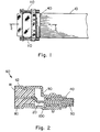
- the apparatus and method of the invention are practiced with a flat cable 10 which includes a plurality of relatively fine insulated wires 20 surrounded by an electrical shielding sheath 40 of aluminum, copper, or the like.
- An insulating jacket 50 encloses the entire assembly of wires and shielding sheath.
- the cable 10 is secured to a terminating connector or plug 60 in a unique manner.
- the plug 60 is made of tin-plated steel or the like and has an annular metal housing 62 which carries an assembly of pins or sockets 80 embedded in an insulating matrix 81.
- the housing 70 includes a rearwardly extending generally S-shaped plate 90 which is soldered to the housing 70 and is adapted to engage one surface of the end of the cable with a similar separate plate 100 which engages the opposite surface of the cable. Plate 100 is secured to the plate 90 with the cable between them.
- the shield 40 is turned back so that the individual wires 20 are exposed and enough insulation is removed so that each can be secured to a pin or socket 80.
- the shield 40 which is turned back covers the insulating jacket 50, as seen in Fig. 2, and it is clamped between the plates 90 and 100 with the shield between and in electrical contact with the plates 90 and 100.
- the plates are secured together by bolts, screws, or the like.
- the connector 60 carrying the cable 10 is coupled to a terminal chassis (not shown) or the like and is grounded for optimum operation by means of thumb screws 110 which secure the metal housing 62 to the chassis.
- the other end of the cable 10 can be prepared and secured to a connector in similar fashion, if desired.
- the assembly described provides optimum shielding of a multi-conductor cable from electrical and electrostatic fields.
- the body of the connector itself provides a shielding action for electric fields, and the connection to the chassis provides a path for electrostatic discharge.
Landscapes
- Details Of Connecting Devices For Male And Female Coupling (AREA)
- Multi-Conductor Connections (AREA)
Applications Claiming Priority (2)
| Application Number | Priority Date | Filing Date | Title |
|---|---|---|---|
| US52440483A | 1983-08-18 | 1983-08-18 | |
| US524404 | 1990-05-16 |
Publications (2)
| Publication Number | Publication Date |
|---|---|
| EP0135122A2 true EP0135122A2 (fr) | 1985-03-27 |
| EP0135122A3 EP0135122A3 (fr) | 1987-06-16 |
Family
ID=24089077
Family Applications (1)
| Application Number | Title | Priority Date | Filing Date |
|---|---|---|---|
| EP84109521A Withdrawn EP0135122A3 (fr) | 1983-08-18 | 1984-08-10 | Connecteur de câble et méthode d'accouplement de câble plat à plusieurs fils |
Country Status (3)
| Country | Link |
|---|---|
| EP (1) | EP0135122A3 (fr) |
| JP (1) | JPS6070682A (fr) |
| CA (1) | CA1214231A (fr) |
Cited By (3)
| Publication number | Priority date | Publication date | Assignee | Title |
|---|---|---|---|---|
| DE102005039620A1 (de) * | 2005-08-19 | 2007-03-01 | Erni Elektroapparate Gmbh | Flachbandkabel-Steckverbinder |
| US7503797B2 (en) | 2006-09-26 | 2009-03-17 | Erni Electronics Gmbh | Plug-in connector with strain relief |
| US8236788B2 (en) | 2006-07-24 | 2012-08-07 | Basf Se | Azolylmethyloxiranes, use thereof for controlling plant pathogenic fungi, and agents containing the same |
Family Cites Families (6)
| Publication number | Priority date | Publication date | Assignee | Title |
|---|---|---|---|---|
| US3280246A (en) * | 1965-02-02 | 1966-10-18 | Thomas & Betts Corp | Ground sheath connector |
| US3744128A (en) * | 1971-02-12 | 1973-07-10 | Nasa | Process for making r. f. shielded cable connector assemblies and the products formed thereby |
| US4337989A (en) * | 1980-05-28 | 1982-07-06 | Amp Incorporated | Electromagnetic shielded connector |
| JPS6017812Y2 (ja) * | 1981-06-22 | 1985-05-30 | 日本航空電子工業株式会社 | コネクタフ−ド |
| EP0090539A3 (fr) * | 1982-03-31 | 1985-11-21 | AMP INCORPORATED (a New Jersey corporation) | Connecteur blindé |
| US4514029A (en) * | 1982-05-03 | 1985-04-30 | Quintec Interconnect Systems | Shielded connector and method of forming same |
-
1984
- 1984-08-08 JP JP59166292A patent/JPS6070682A/ja active Granted
- 1984-08-10 EP EP84109521A patent/EP0135122A3/fr not_active Withdrawn
- 1984-08-15 CA CA000461056A patent/CA1214231A/fr not_active Expired
Cited By (5)
| Publication number | Priority date | Publication date | Assignee | Title |
|---|---|---|---|---|
| DE102005039620A1 (de) * | 2005-08-19 | 2007-03-01 | Erni Elektroapparate Gmbh | Flachbandkabel-Steckverbinder |
| US7491085B2 (en) | 2005-08-19 | 2009-02-17 | Erni Electronics Gmbh | Ribbon cable plug-in connector |
| DE102005039620B4 (de) * | 2005-08-19 | 2016-02-18 | Erni Production Gmbh & Co. Kg | Flachbandkabel-Steckverbinder |
| US8236788B2 (en) | 2006-07-24 | 2012-08-07 | Basf Se | Azolylmethyloxiranes, use thereof for controlling plant pathogenic fungi, and agents containing the same |
| US7503797B2 (en) | 2006-09-26 | 2009-03-17 | Erni Electronics Gmbh | Plug-in connector with strain relief |
Also Published As
| Publication number | Publication date |
|---|---|
| EP0135122A3 (fr) | 1987-06-16 |
| JPH0261784B2 (fr) | 1990-12-21 |
| JPS6070682A (ja) | 1985-04-22 |
| CA1214231A (fr) | 1986-11-18 |
Similar Documents
| Publication | Publication Date | Title |
|---|---|---|
| US4579415A (en) | Grounding of shielded cables in a plug and receptacle electrical connector | |
| US4846724A (en) | Shielded cable assembly comprising means capable of effectively reducing undesirable radiation of a signal transmitted through the assembly | |
| KR100390311B1 (ko) | 전송 특성이 향상된 차폐 케이블 커넥터 | |
| US4619487A (en) | Flat cable connector with grounding clip | |
| US5823825A (en) | System for terminating the shield of a high speed cable | |
| JP3015944B2 (ja) | 高速伝送線のシールド終端装置 | |
| EP0094173B1 (fr) | Connecteur électrique à élément commun de connexion | |
| JP3015939B2 (ja) | 高速伝送ケーブルのシールドの終端装置 | |
| US10777936B2 (en) | Electrical device having a ground termination component with strain relief | |
| US5785555A (en) | System for terminating the shield of a high speed cable | |
| US5718607A (en) | System for terminating the shield of a high speed cable | |
| US5961348A (en) | System for terminating the shield of a high speed cable | |
| EP0305186A2 (fr) | Connecteurs électriques à écran | |
| US5387125A (en) | Connector for flexible flat cable | |
| US4624515A (en) | Electrical connector with grounding clip | |
| EP0431206B1 (fr) | Connecteur à blindage de mise à la terre et procédé | |
| US4447100A (en) | Apparatus for grounding and terminating a cable | |
| US5768771A (en) | System for terminating the shield of a high speed cable | |
| US6364701B1 (en) | System for terminating the shield of a high speed cable | |
| EP0111162A1 (fr) | Connecteur enfermé, blindé et mis à la terre | |
| EP0429962B1 (fr) | Connecteur pour câble multiconducteur et procédé de branchement | |
| US4639053A (en) | Connector for a shielded flat cable | |
| US4613191A (en) | Grounding connector | |
| CA1214231A (fr) | Connecteur de cables, et methode de raccordement de cables multiconducteur en nappe | |
| US4627673A (en) | Grounding and strain relief clamp for flat cables |
Legal Events
| Date | Code | Title | Description |
|---|---|---|---|
| PUAI | Public reference made under article 153(3) epc to a published international application that has entered the european phase |
Free format text: ORIGINAL CODE: 0009012 |
|
| AK | Designated contracting states |
Designated state(s): BE DE FR GB IT NL SE |
|
| RAP1 | Party data changed (applicant data changed or rights of an application transferred) |
Owner name: BURROUGHS CORPORATION (A DELAWARE CORPORATION) |
|
| PUAL | Search report despatched |
Free format text: ORIGINAL CODE: 0009013 |
|
| AK | Designated contracting states |
Kind code of ref document: A3 Designated state(s): BE DE FR GB IT NL SE |
|
| STAA | Information on the status of an ep patent application or granted ep patent |
Free format text: STATUS: THE APPLICATION IS DEEMED TO BE WITHDRAWN |
|
| 18D | Application deemed to be withdrawn |
Effective date: 19871217 |
|
| RIN1 | Information on inventor provided before grant (corrected) |
Inventor name: IOSSO, THOMAS PETER |