EP0135240A2 - Selbsttragende Platte für einen doppelten Fussboden - Google Patents
Selbsttragende Platte für einen doppelten Fussboden Download PDFInfo
- Publication number
- EP0135240A2 EP0135240A2 EP84201312A EP84201312A EP0135240A2 EP 0135240 A2 EP0135240 A2 EP 0135240A2 EP 84201312 A EP84201312 A EP 84201312A EP 84201312 A EP84201312 A EP 84201312A EP 0135240 A2 EP0135240 A2 EP 0135240A2
- Authority
- EP
- European Patent Office
- Prior art keywords
- slab
- concrete
- slab according
- ribs
- cavities
- Prior art date
- Legal status (The legal status is an assumption and is not a legal conclusion. Google has not performed a legal analysis and makes no representation as to the accuracy of the status listed.)
- Withdrawn
Links
- 230000002093 peripheral effect Effects 0.000 claims abstract description 21
- 239000011150 reinforced concrete Substances 0.000 claims abstract description 7
- 239000004567 concrete Substances 0.000 claims description 33
- 235000000396 iron Nutrition 0.000 claims description 11
- 239000000835 fiber Substances 0.000 claims description 8
- 230000002787 reinforcement Effects 0.000 claims description 7
- 238000004519 manufacturing process Methods 0.000 claims description 5
- PMVSDNDAUGGCCE-TYYBGVCCSA-L Ferrous fumarate Chemical compound [Fe+2].[O-]C(=O)\C=C\C([O-])=O PMVSDNDAUGGCCE-TYYBGVCCSA-L 0.000 claims description 4
- 229910000831 Steel Inorganic materials 0.000 claims description 4
- 239000000463 material Substances 0.000 claims description 4
- 239000002184 metal Substances 0.000 claims description 4
- 229910052751 metal Inorganic materials 0.000 claims description 4
- 230000003014 reinforcing effect Effects 0.000 claims description 4
- 239000011347 resin Substances 0.000 claims description 4
- 229920005989 resin Polymers 0.000 claims description 4
- 239000010959 steel Substances 0.000 claims description 4
- 230000003247 decreasing effect Effects 0.000 claims description 3
- 239000004033 plastic Substances 0.000 claims description 3
- 238000003466 welding Methods 0.000 claims description 2
- 229920000914 Metallic fiber Polymers 0.000 description 5
- 239000011324 bead Substances 0.000 description 5
- 239000011521 glass Substances 0.000 description 5
- 238000005452 bending Methods 0.000 description 4
- 238000004080 punching Methods 0.000 description 4
- 239000010410 layer Substances 0.000 description 2
- 238000012423 maintenance Methods 0.000 description 2
- 239000000203 mixture Substances 0.000 description 2
- 239000002245 particle Substances 0.000 description 2
- 239000004793 Polystyrene Substances 0.000 description 1
- 239000011398 Portland cement Substances 0.000 description 1
- 241001639412 Verres Species 0.000 description 1
- 239000004568 cement Substances 0.000 description 1
- 239000004927 clay Substances 0.000 description 1
- 238000004140 cleaning Methods 0.000 description 1
- 239000011248 coating agent Substances 0.000 description 1
- 239000011247 coating layer Substances 0.000 description 1
- 238000000576 coating method Methods 0.000 description 1
- 239000002131 composite material Substances 0.000 description 1
- 238000010276 construction Methods 0.000 description 1
- -1 etc. combined or not Substances 0.000 description 1
- 238000009434 installation Methods 0.000 description 1
- 238000012986 modification Methods 0.000 description 1
- 230000004048 modification Effects 0.000 description 1
- 229920002223 polystyrene Polymers 0.000 description 1
- 230000005855 radiation Effects 0.000 description 1
- 239000004576 sand Substances 0.000 description 1
- 230000035939 shock Effects 0.000 description 1
- 229920002994 synthetic fiber Polymers 0.000 description 1
- 230000035899 viability Effects 0.000 description 1
- XLYOFNOQVPJJNP-UHFFFAOYSA-N water Substances O XLYOFNOQVPJJNP-UHFFFAOYSA-N 0.000 description 1
- 239000002023 wood Substances 0.000 description 1
Images
Classifications
-
- E—FIXED CONSTRUCTIONS
- E04—BUILDING
- E04F—FINISHING WORK ON BUILDINGS, e.g. STAIRS, FLOORS
- E04F15/00—Flooring
- E04F15/02—Flooring or floor layers composed of a number of similar elements
- E04F15/024—Sectional false floors, e.g. computer floors
- E04F15/02405—Floor panels
Definitions
- the present invention relates to a self-supporting and removable slab, made of concrete, such as cement concrete, resin concrete, light concrete, etc., intended to be supported in the vicinity of its angles for the production of a false- modular floor.
- the tiles must be removable in order to allow access at all times to the power cables and equipment of the various aforementioned devices.
- the aforementioned jacks supporting the slabs being adjustable, which allows rectify the unevenness of the base floor to obtain a good flatness of the raised sub-floor.
- the slabs must have a minimum deflection under load which is linked to the bearing capacity. The less the slab bends, the more stable the support of the devices.
- the slabs must also be of high dimensional accuracy so that, on the one hand, they can be laid edge to edge with practically no joints and, on the other hand, so that the lower and upper faces of the slabs, once laid, are located in two parallel planes, the regularity of the dimensions at the angles, where the slabs are supported by the jacks, being particularly important. Failure to comply with this latter requirement would destroy the viability and aesthetics of the raised floor, reduce its fire resistance and make cleaning and maintenance difficult.
- the tiles must be light to allow easy installation and handling, but also because any increase in weight of the raised floor leads to a reduction in the admissible payload of the base floor.
- the tiles must be able to withstand the fire as long as possible without losing their bearing capacity.
- Said slabs must also have an acoustic attenuating power to avoid the propagation of sound due to the fact that the floor and the raised floor form a sounding board. Since the surface of a raised floor will never be a perfect multiple of the standard dimensions of a slab, it must be possible to cut in any direction while continuing to meet the above requirements.
- the slab should have a wear-resistant upper surface which would be more decorative, which would make it unnecessary to lay, as is done on virtually all slabs used to date, a coating layer, such as carpet, synthetic material, rubber material, etc ...
- the known slabs made of concrete have the particular disadvantage of having a too high weight because of their profile and their composition, while metal slabs, wooden slabs, metal-wood composite slabs or metal-light concrete, etc., have the particular disadvantage of having too large arrows under load, of offering insufficient resistance to fire, and of not offering acoustic attenuation.
- the object of the invention is to remedy the drawbacks of known slabs and to provide a new reinforced concrete slab, of reduced density, with or without the addition of fibers, such as metallic fibers, having an upper surface resistant to wear and having an appearance that is decorative enough to require no coating, this slab also offering the advantage of simultaneously meeting all the requirements listed above.
- the slab is made of reinforced concrete, the upper and lateral faces of the slab being flat, the latter having, from its lower face, cavities, regularly distributed and aligned in two transverse directions. , arranged so that their side walls delimit, on the one hand, with the underside of the slab, stiffening ribs extending and intersecting in the two above directions and, on the other hand, with the side faces of the slab and the underside thereof, a peripheral radiation rib.
- the concrete constituting the slab is a light concrete, with a dry density between 850 and 1500 kg / m 3
- the irons constituting the reinforcement of the slab are embedded in the aforementioned stiffening ribs, at least one iron being provided in each of the ribs, the irons embedded in the peripheral stiffening rib having a larger section than that of the irons embedded in the other ribs.
- the section of the stiffening ribs is substantially constant over their entire length.
- the section of the peripheral stiffening rib is substantially constant over the entire periphery of the slab while the section of the ribs extending inside the peripheral rib is variable, the dimension of these ribs taken perpendicularly to the upper face of the slab decreasing regularly from the periphery of the slab towards the center of the latter.
- the light concrete is based on aggregates of a very reduced density such as expanded glass beads, expanded clay beads, polystyrene beads, etc. combined or not, fibers, preferably metallic, being distributed in a homogeneous way in the mass of concrete.
- the self-supporting and removable concrete slab 1, according to the invention and shown in the drawings, is intended to be supported in the vicinity of its angles for the production of a modular raised floor.
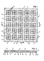
- This slab is made of reinforced concrete and its upper 2 and lateral 3 faces are flat, the slab having, from its lower face 4 cavities 5, regularly distributed and aligned in two transverse directions shown diagrammatically by the arrows 6 and 7, arranged so that their side walls 8 delimit, on the one hand, with the lower face 4 of the slab, ribs of stiffening 9 and 10 extending and intersecting in the two above directions and, on the other hand, with the lateral faces 3 of the slab and the lower face 4 of the latter, a peripheral stiffening rib 11.
- the concrete constituting the slab is a light concrete with a dry density between 850 and 1500 kg / m 3 .
- the bars 12 constituting the reinforcement of the slab are embedded in the stiffening ribs 9, 10 and 11, at least one iron 12 being provided in each of the ribs, the bars embedded in the peripheral stiffening rib 11 having a larger section as that of the irons embedded in the other ribs 9 and 10, said irons 12 are situated substantially at the same level and are joined together by welding to form a trellis.
- the slab 1 illustrated in the drawings is a square slab and the two directions 6 and 7 are parallel to two contiguous sides of the slab.
- the sections of the cavities 5, taken parallel to the upper face 2 of the slab have the same shape as the corresponding section of the slab.
- the sections of the stiffening ribs 9, 10 and 11 by planes perpendicular to the aforementioned directions are substantially in the form of isosceles trapezoids, the small base of these trapezoids coinciding with the lower face 4 of the slab.
- the section of the stiffening ribs 9, 10 and 11, by the above perpendicular planes, is substantially constant over their entire length.
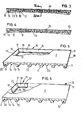
- said slab can have, as shown in FIGS. 3 and 4, a peripheral stiffening rib 11 which has a substantially constant section around the entire periphery of the slab, while the section of the ribs 9 and 10 extending inside the peripheral rib 10 is variable, the dimension of these ribs 9 and 10, corresponding to the height of the abovementioned trapezoids, decreasing regularly from the periphery of the slab towards the center of the latter.
- the reinforcement of the concrete advantageously comprises metallic fibers, such as steel fibers, not shown, embedded in the entire mass of the stick constituting the slab.
- the bottoms 13 of the cavities 5 are substantially planar and parallel to the upper face 2 of the slab.
- the bottoms 13 of the latter are provided with stiffening ribs 14 extending from their center towards the walls 8 of the cavities.
- the stiffening ribs 14 presented by the bottoms of the cavities can be substantially parallel to the two directions 6 and 7 above, these ribs 14 having, for example, a constant section in the form of an isosceles triangle, the base of the latter coinciding with the bottom 13 of the cavity 5.
- the peripheral stiffening rib 11 may comprise a reinforcing element 15 associated, around the entire periphery of the slab, either at least part of the height of the side walls 3 of the slab, or at at least this part and at least part of the faces 20 of said peripheral rib, this element 15, intended to withstand shocks, being rigid and made of metal, plastic or even resin concrete.
- this element 15 consists of profiles 16, assembled at the location of the side edges 17 of the slab, which have two wings 18 and 19, the wings 18 constituting the side walls 3 of the slab, while that their wings 19 constitute a part of the faces 20 of the peripheral rib 11 which are parallel to the upper face 2 of the slab.
- the peripheral rib 11 is lined, at the location of the lateral edges 17 and on either side thereof, of reinforcing elements 15 each consisting of two sections 21 and 22, substantially equal, of a rigid profile, made of metal, plastic or resin concrete, having two wings 18 and 19.
- These sections 21 and 22 are joined together by one of their ends and their wings 18 and 19 extend, in the vicinity of the edges 17 of the slab, over the entire height of the lateral faces 3 of the latter and over part of the width of the faces 20 specified tees of the peripheral rib 11.
- the slab according to the invention advantageously has, at its upper face 2, a layer of material 24, wear resistant, which is integral with the concrete constituting the slab.
- This layer of material 24 can be constituted by a concrete known by the name of terrazzo type concrete.
- the upper face 2 is advantageously polished to give the slab the appearance of a tiling, as well as to facilitate the maintenance of the raised floor.
- the concrete that constitutes this slab is composed, per m 3 , of approximately 875 liters of expanded glass beads of particle size 2/6, of approximately 493 kg of Rhine sand of particle size 0/2, of approximately 502 kg of Portland cement 50, approximately 5 kg of super-fluidizer, without steel fibers or with approximately 26 kg of steel fibers whose diameter is of the order of 0.4 mm and the length of which is of the order of 40 mm and of approximately 187 liters of water.
Landscapes
- Engineering & Computer Science (AREA)
- Architecture (AREA)
- General Engineering & Computer Science (AREA)
- Civil Engineering (AREA)
- Structural Engineering (AREA)
- Forms Removed On Construction Sites Or Auxiliary Members Thereof (AREA)
- Building Environments (AREA)
- Floor Finish (AREA)
Applications Claiming Priority (2)
| Application Number | Priority Date | Filing Date | Title |
|---|---|---|---|
| BE211562 | 1983-09-21 | ||
| BE211562 | 1983-09-21 |
Publications (2)
| Publication Number | Publication Date |
|---|---|
| EP0135240A2 true EP0135240A2 (de) | 1985-03-27 |
| EP0135240A3 EP0135240A3 (de) | 1986-03-19 |
Family
ID=3843682
Family Applications (1)
| Application Number | Title | Priority Date | Filing Date |
|---|---|---|---|
| EP84201312A Withdrawn EP0135240A3 (de) | 1983-09-21 | 1984-09-12 | Selbsttragende Platte für einen doppelten Fussboden |
Country Status (1)
| Country | Link |
|---|---|
| EP (1) | EP0135240A3 (de) |
Cited By (4)
| Publication number | Priority date | Publication date | Assignee | Title |
|---|---|---|---|---|
| GB2181171A (en) * | 1985-09-27 | 1987-04-15 | Intek Floors Ltd | Concrete slab for a false or platform floor having strengthening ribs on the underside |
| GB2202248A (en) * | 1987-02-06 | 1988-09-21 | John Joseph Nash | Insulating board with raised rib on one face at the periphery |
| EP0279278A3 (en) * | 1987-02-19 | 1988-10-12 | Mahle Gmbh | Frame for a supported flooring panel of sectional false floors, especially for corners |
| GB2614906A (en) * | 2022-01-24 | 2023-07-26 | Dideco Ltd | Composite floor construction |
Family Cites Families (8)
| Publication number | Priority date | Publication date | Assignee | Title |
|---|---|---|---|---|
| US3295272A (en) * | 1963-08-07 | 1967-01-03 | Furukawa Casting Company Ltd | Raised floor construction |
| FR1523900A (fr) * | 1967-05-24 | 1968-05-03 | Const Metalliques M G Sa Des | Plancher surélevé réglable |
| CA854940A (en) * | 1967-10-02 | 1970-11-03 | H. Bruce James | Construction panel and method of producing same |
| DE2307815B2 (de) * | 1973-02-16 | 1976-01-02 | Guenter H. 1000 Berlin Kiss | Schall- und wärmedämmende Fußbodenplatte |
| US4067156A (en) * | 1976-01-12 | 1978-01-10 | Donn Products, Inc. | Computer floor structure |
| GB2030630A (en) * | 1978-09-29 | 1980-04-10 | Rintoul Pty Ltd | Floor Tile |
| FR2517714A1 (fr) * | 1981-12-09 | 1983-06-10 | Harnois Georges | Procede et dispositif pour la realisation d'une aire de circulation ou plate-forme, sensiblement plane |
| CA1206346A (en) * | 1983-11-04 | 1986-06-24 | Richard P. Morris | Concrete floor panel and floor system |
-
1984
- 1984-09-12 EP EP84201312A patent/EP0135240A3/de not_active Withdrawn
Cited By (6)
| Publication number | Priority date | Publication date | Assignee | Title |
|---|---|---|---|---|
| GB2181171A (en) * | 1985-09-27 | 1987-04-15 | Intek Floors Ltd | Concrete slab for a false or platform floor having strengthening ribs on the underside |
| EP0219985A3 (de) * | 1985-09-27 | 1988-08-10 | Intek Floors Limited | Betonfliese für einen aufgeständerte Fussboden |
| GB2202248A (en) * | 1987-02-06 | 1988-09-21 | John Joseph Nash | Insulating board with raised rib on one face at the periphery |
| GB2202248B (en) * | 1987-02-06 | 1991-04-17 | John Joseph Nash | Insulation board |
| EP0279278A3 (en) * | 1987-02-19 | 1988-10-12 | Mahle Gmbh | Frame for a supported flooring panel of sectional false floors, especially for corners |
| GB2614906A (en) * | 2022-01-24 | 2023-07-26 | Dideco Ltd | Composite floor construction |
Also Published As
| Publication number | Publication date |
|---|---|
| EP0135240A3 (de) | 1986-03-19 |
Similar Documents
| Publication | Publication Date | Title |
|---|---|---|
| EP2466029B1 (de) | Wärmeisolierende Kontaktplatte | |
| FR2562837A1 (fr) | Elements composites de construction et procede pour la realisation de structures multi-directionnelles par formage et/ou assemblage de tels elements | |
| FR3002777A1 (fr) | Bloc de construction hybride structural/isolant | |
| EP1470302B1 (de) | Modulares fussbodensystem mit rahmenfliesen | |
| EP1045089A1 (de) | Mauerwerkstruktur und Verfahren zu deren Verstärkung | |
| CA3106583A1 (fr) | Plaque et dalle destinees a realiser un plancher ou une paroi et procedes de fabrication de telles plaque et dalle | |
| WO2000046458A1 (fr) | Dalle de construction, assemblage de telles dalles et utilisation pour realiser des structures pouvant supporter des charges importantes | |
| FR3066514B1 (fr) | Coffrage perdu isolant et procede associe pour realiser un mur. | |
| BE897801A (fr) | Dalle autoportante pour faux-plancher | |
| EP0360682B1 (de) | Dehnungsfuge für Betonbodenbelag | |
| FR2956422A1 (fr) | Poutrelle metallique pour la fabrication de planchers. | |
| BE1011072A3 (fr) | Element de construction prefabrique et son procede de fabrication. | |
| FR2770239A1 (fr) | Element de construction pour plancher prefabrique | |
| EP3320154B1 (de) | Bauteil und herstellungsverfahren eines solchen bauelements | |
| FR2707321A1 (fr) | Procédé de construction de piscine. | |
| FR2540165A1 (fr) | Dispositif de fixation pour elements de construction rapportes formant facade et procede de montage de ces elements | |
| WO2011061414A1 (fr) | Structure porteuse | |
| FR2597907A2 (fr) | Parpaing isolant par l'exterieur | |
| FR2530705A1 (fr) | Elements de construction pour la prefabrication notamment de planchers | |
| FR2953872A1 (fr) | Panneau monobloc prefabrique multi-couche | |
| FR2885624A1 (fr) | Procede de construction d'un batiment prefabrique et element constitutif de ce batiment | |
| EP0474543B1 (de) | Selbsttragendes Leichtbauwandelement | |
| WO2016132195A1 (fr) | Element de construction et procede de montage d'un tel element de construction | |
| WO2019211661A1 (fr) | Procede de fabrication d'un plancher, plancher et element de coffrage a etai integre associes | |
| FR3041672A1 (fr) | Coque de piscine en matiere plastique pourvue d'elements de renfort |
Legal Events
| Date | Code | Title | Description |
|---|---|---|---|
| PUAI | Public reference made under article 153(3) epc to a published international application that has entered the european phase |
Free format text: ORIGINAL CODE: 0009012 |
|
| AK | Designated contracting states |
Designated state(s): AT BE CH DE FR GB IT LI LU NL SE |
|
| PUAL | Search report despatched |
Free format text: ORIGINAL CODE: 0009013 |
|
| AK | Designated contracting states |
Kind code of ref document: A3 Designated state(s): AT BE CH DE FR GB IT LI LU NL SE |
|
| STAA | Information on the status of an ep patent application or granted ep patent |
Free format text: STATUS: THE APPLICATION HAS BEEN WITHDRAWN |
|
| 18W | Application withdrawn |
Withdrawal date: 19860722 |
|
| RIN1 | Information on inventor provided before grant (corrected) |
Inventor name: VAN ACKER, ARNOLD EMIEL MARIE Inventor name: VERMEULEN, GHISLAIN GUSTAAF AMANDUS |