EP0135251A2 - Hotte d'aspiration - Google Patents
Hotte d'aspiration Download PDFInfo
- Publication number
- EP0135251A2 EP0135251A2 EP84303627A EP84303627A EP0135251A2 EP 0135251 A2 EP0135251 A2 EP 0135251A2 EP 84303627 A EP84303627 A EP 84303627A EP 84303627 A EP84303627 A EP 84303627A EP 0135251 A2 EP0135251 A2 EP 0135251A2
- Authority
- EP
- European Patent Office
- Prior art keywords
- air
- chamber
- cabinet
- safety cabinet
- transfer ducts
- Prior art date
- Legal status (The legal status is an assumption and is not a legal conclusion. Google has not performed a legal analysis and makes no representation as to the accuracy of the status listed.)
- Withdrawn
Links
Images

Classifications
-
- B—PERFORMING OPERATIONS; TRANSPORTING
- B08—CLEANING
- B08B—CLEANING IN GENERAL; PREVENTION OF FOULING IN GENERAL
- B08B15/00—Preventing escape of dirt or fumes from the area where they are produced; Collecting or removing dirt or fumes from that area
- B08B15/02—Preventing escape of dirt or fumes from the area where they are produced; Collecting or removing dirt or fumes from that area using chambers or hoods covering the area
- B08B15/023—Fume cabinets or cupboards, e.g. for laboratories
Definitions
- This invention concerns a safety cabinet of the kind providing an opening to a working chamber into which a user may introduce his hands for manipulating materials, articles, reagents and the like in said chamber, means being provided for drawing air from the working chamber in such a way as to create a barrier of air at the opening, and for re-circulating the air, after filtration, to the chamber.
- Such cabinets (hereinafter referred to as "of the kind referred to") are used, for instance, in laboratories, e.g. for microbiological and chemical work.
- a fan chamber which houses a fan and is separated from the working chamber by a main filter.
- An air entry compartment is disposed above the fan chamber and separated from the latter by an entry filter.
- An air space below the working chamber and connected with the latter communicates with the air entry compartment by way of an air transfer duct extending up the back of the cabinet, and occupying substantially the entire width thereof.
- An object of the present invention is to provide an improved safety cabinet construction in which these disadvantages are obviated, the cabinet being serviceable either from the front or the back as desired and being capable of being constructed with relatively small front-to-rear dimensions.
- the present invention provides a safety cabinet of the kind referred to having a fan clamber housing one or more disposed above a work chamber, an air entry compartment above the fan chamber and an air space below the working chamber, characterised by provision of air transfer ducts extending upwards of the two sides of the cabinet so as to connect the lower air space to the air entry compartment.
- the arrangement is preferably such that at the rear of the lower part of the working chamber there is a rear exhaust chamber connecting the lower air space to the air transfer ducts.
- a plurality of guide channels preferably extend between the rear exhaust chamber and the air transfer ducts.
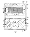
- a preferred embodiment of the safety cabinet of the invention is oonstructed principally of sheet metal and comprises a housing including a front panel 10 having peripheral fixing flanges 12, rear panels 66, 68, 70 & 72, top and bottom panels 16, 18 respectively, and sidewalls 20, 22 respectively.
- the lower part of the interior of the housing constitutes a working chamber 24 of the cabinet.
- the top of the chamber 24 is defined by a main filter 26, preferably a HEPA filter
- the bottom of the chamber 24 is defined by a working surface 28 spaced above the bottom panel 18 of the housing so as to define an air space 30 therebetween.
- the working surface 28 may, in certain instances, be perforate, but normally, as shown, the working surface will be imperforate and provided with a peripheral rim or lip 32.
- a gap remains between the working surface 28 and the front and rear of the wording chamber 24.
- the front panel 10 is recessed inwards as at 34 (Fig. 2) and is formed with an access opening 36, the upper part of which is screened by a removable transparent panel 38 held in place by knobs 40.
- an access opening 36 By way of the opening 36 a user can reach into the working chamber 24 with his hands and work on and/or manipulate articles, materials, reagents and so on, on the working surface 28.
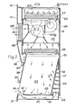
- the main filter 26 serves as the ceiling of the working chamber 24 and separates the latter from a fan chamber 42 (see particularly Fig. 2) accommodating an outlet filter fan 14 and two main filter fans 44a.
- the fan chamber 42 has a front wall 46 spaced inwards from the upper part of the front panel 10, in which there is an air outlet aperture 48.
- An outlet filter 50 is provided in this aperture 48 and the air output from the outlet fan 14 is able to pass out of the cabinet by way of this aperture 48.
- an air entry compartment 54 Above the fan chamber 42 and separated from the latter by an entry filter 52 is an air entry compartment 54.
- the rear of the working chamber 24 is provided with an inclined baffle 56 which serves to define, at the lower part of the wording chamber 24, a rear exhaust chamber 58.
- This latter chamber 58 communicates with the ari entry compartment 54 by way of air transfer ducts 60 (see Fig. 1) extending upwards of the two sides of the cabinet and cefined by secondary walls 62 extending upwards from the sides of the working surface 28 and spaced a small distance away from the respective side panels 20, 22.
- the rear exhaust chamber 58 leads into the air transfer ducts 60 by way of a plurality of guide channels 64 at left and right.
- Fig. 2 of the drawings indicate, schematically, the course of the air circulation which occurs in the cabinet when the fans 14, 44a, 44b are in operation.
- the air output from the fan 14 is able to pass through the output filter 50 and out of the cabinet by way of the aperture 48.
- the remainder of the output of air from fans 44a, 44b is able to pass through the main filter 26 and into the working chamber 24 where it serves to provide a current of filtered air over the user's hands working in the chamber 24.
- Some of this air flows over the front edge of the working surface 28 and into the air space 30 therebelow.
- some of the air flows over the back edge of the wording auriace 28.
- the transfer ducts 60 extend up the sides of the cabinet, they do not inhibit access to the interior of the cabinet by way of the front or rear thereof, e.g. for servicing.
- the rear panel in the illustrated embodiment is constructed of removable sections 66, 68, 70, 72 for this purpose.
- the front to rear dimensions of the cabinet are lesser than would be the case where an air transfer duct is provided up. the rear of the cabinet between the air space 30 and the entry compartment 54, for an equal depth of working chamber 24.
- the air transfer ducts 60 may each be divided by suitable partitions (not shown) into a plurality of individual guide channels.
- the arrangement of the wording surface 28 and the secondary walls 62 may be such that the air space 30 communicates directly with the lower ends of the air transfer ducts 60.
- Other modifications are possible.
Landscapes
- Apparatus Associated With Microorganisms And Enzymes (AREA)
- Filtering Of Dispersed Particles In Gases (AREA)
- Respiratory Apparatuses And Protective Means (AREA)
- Ventilation (AREA)
Applications Claiming Priority (2)
| Application Number | Priority Date | Filing Date | Title |
|---|---|---|---|
| GB838323085A GB8323085D0 (en) | 1983-08-26 | 1983-08-26 | Safety cabinet |
| GB8323085 | 1983-08-26 |
Publications (2)
| Publication Number | Publication Date |
|---|---|
| EP0135251A2 true EP0135251A2 (fr) | 1985-03-27 |
| EP0135251A3 EP0135251A3 (fr) | 1987-07-01 |
Family
ID=10547958
Family Applications (1)
| Application Number | Title | Priority Date | Filing Date |
|---|---|---|---|
| EP84303627A Withdrawn EP0135251A3 (fr) | 1983-08-26 | 1984-05-30 | Hotte d'aspiration |
Country Status (2)
| Country | Link |
|---|---|
| EP (1) | EP0135251A3 (fr) |
| GB (2) | GB8323085D0 (fr) |
Cited By (2)
| Publication number | Priority date | Publication date | Assignee | Title |
|---|---|---|---|---|
| WO1995014195A1 (fr) * | 1993-11-16 | 1995-05-26 | Anthos Labtec Instruments Ges.Mbh | Etabli de securite |
| FR2911520A1 (fr) * | 2007-01-19 | 2008-07-25 | Roblin Sas Soc Par Actions Sim | Hotte aspirante pour cuisine |
Families Citing this family (3)
| Publication number | Priority date | Publication date | Assignee | Title |
|---|---|---|---|---|
| GB9401821D0 (en) * | 1994-01-31 | 1994-03-23 | Mdh Ltd | Isolator and method of operating it |
| CN104144753B (zh) * | 2011-12-05 | 2017-03-01 | 艾森特崇越私人有限公司 | 用于药品的制备的机器 |
| KR102004356B1 (ko) * | 2018-01-03 | 2019-10-01 | 주식회사 제이오텍 | 안전 캐비닛 |
Family Cites Families (3)
| Publication number | Priority date | Publication date | Assignee | Title |
|---|---|---|---|---|
| US2627220A (en) * | 1950-11-04 | 1953-02-03 | Sheldon & Co E H | Fume hood |
| US3895570A (en) * | 1973-09-27 | 1975-07-22 | Baker Company Inc | Air-insulated work station |
| GB1593597A (en) * | 1978-05-23 | 1981-07-22 | Howarth Air Eng Ltd | Work cabinet |
-
1983
- 1983-08-26 GB GB838323085A patent/GB8323085D0/en active Pending
-
1984
- 1984-05-30 GB GB08413794A patent/GB2145513B/en not_active Expired
- 1984-05-30 EP EP84303627A patent/EP0135251A3/fr not_active Withdrawn
Cited By (3)
| Publication number | Priority date | Publication date | Assignee | Title |
|---|---|---|---|---|
| WO1995014195A1 (fr) * | 1993-11-16 | 1995-05-26 | Anthos Labtec Instruments Ges.Mbh | Etabli de securite |
| FR2911520A1 (fr) * | 2007-01-19 | 2008-07-25 | Roblin Sas Soc Par Actions Sim | Hotte aspirante pour cuisine |
| WO2008090080A1 (fr) * | 2007-01-19 | 2008-07-31 | Roblin Sas | Hotte aspirante pour cuisine |
Also Published As
| Publication number | Publication date |
|---|---|
| EP0135251A3 (fr) | 1987-07-01 |
| GB8323085D0 (en) | 1983-09-28 |
| GB2145513A (en) | 1985-03-27 |
| GB8413794D0 (en) | 1984-07-04 |
| GB2145513B (en) | 1986-07-09 |
Similar Documents
| Publication | Publication Date | Title |
|---|---|---|
| US4832717A (en) | Clean air cabinet | |
| US3318076A (en) | Dust-free bench | |
| US4562827A (en) | Downdraft countertop cooking range | |
| EP0005925A1 (fr) | Poste de travail | |
| US3870494A (en) | Grease filter for kitchen ventilators | |
| US5042456A (en) | Air canopy ventilation system | |
| US10900665B2 (en) | Combination appliance having a cooktop and steam extraction device | |
| US5995368A (en) | Air flow distribution device for shelf-based circuit cards | |
| US7048625B2 (en) | Clean bench for cleaning atmosphere of partitioned space | |
| AU737950B2 (en) | Control cabinet with cooling device | |
| DK502185A (da) | Luftrenser | |
| EP0135251A2 (fr) | Hotte d'aspiration | |
| US5407389A (en) | Fume hood | |
| US5113749A (en) | Air curtain producing an outward ramping effect for use with an access way or enclosure | |
| EP3338029B1 (fr) | Appareil combiné avec plaque de cuisson et dispositif d'evacuation des fumées | |
| US5927268A (en) | Smoke exhauster | |
| RU2139644C1 (ru) | Микроволновая печь | |
| US3336855A (en) | Ultraclean work station | |
| EP2103351A1 (fr) | Système de confinement de laboratoire | |
| RU2553962C2 (ru) | Воздуходувное устройство | |
| US4137831A (en) | Clean air zone | |
| US6229112B1 (en) | Air handling system for a laser-equipped machine tool | |
| JPS62218747A (ja) | 天井内埋込形換気装置 | |
| US3199435A (en) | Vent hood and blower device usable therein | |
| CA1304998C (fr) | Table de travail propre |
Legal Events
| Date | Code | Title | Description |
|---|---|---|---|
| PUAI | Public reference made under article 153(3) epc to a published international application that has entered the european phase |
Free format text: ORIGINAL CODE: 0009012 |
|
| AK | Designated contracting states |
Designated state(s): BE CH DE FR LI LU NL SE |
|
| 17P | Request for examination filed |
Effective date: 19850504 |
|
| PUAL | Search report despatched |
Free format text: ORIGINAL CODE: 0009013 |
|
| AK | Designated contracting states |
Kind code of ref document: A3 Designated state(s): BE CH DE FR LI LU NL SE |
|
| STAA | Information on the status of an ep patent application or granted ep patent |
Free format text: STATUS: THE APPLICATION HAS BEEN WITHDRAWN |
|
| 18W | Application withdrawn |
Withdrawal date: 19870626 |
|
| RIN1 | Information on inventor provided before grant (corrected) |
Inventor name: HOWORTH, FREDERICK HUGH |