EP0135361B1 - Appareil pour la détection de particules en suspension - Google Patents
Appareil pour la détection de particules en suspension Download PDFInfo
- Publication number
- EP0135361B1 EP0135361B1 EP84305513A EP84305513A EP0135361B1 EP 0135361 B1 EP0135361 B1 EP 0135361B1 EP 84305513 A EP84305513 A EP 84305513A EP 84305513 A EP84305513 A EP 84305513A EP 0135361 B1 EP0135361 B1 EP 0135361B1
- Authority
- EP
- European Patent Office
- Prior art keywords
- light
- chamber
- cone
- detection apparatus
- wall
- Prior art date
- Legal status (The legal status is an assumption and is not a legal conclusion. Google has not performed a legal analysis and makes no representation as to the accuracy of the status listed.)
- Expired - Lifetime
Links
Images
Classifications
-
- G—PHYSICS
- G08—SIGNALLING
- G08B—SIGNALLING SYSTEMS, e.g. PERSONAL CALLING SYSTEMS; ORDER TELEGRAPHS; ALARM SYSTEMS
- G08B17/00—Fire alarms; Alarms responsive to explosion
- G08B17/10—Actuation by presence of smoke or gases, e.g. automatic alarm devices for analysing flowing fluid materials by the use of optical means
- G08B17/103—Actuation by presence of smoke or gases, e.g. automatic alarm devices for analysing flowing fluid materials by the use of optical means using a light emitting and receiving device
- G08B17/107—Actuation by presence of smoke or gases, e.g. automatic alarm devices for analysing flowing fluid materials by the use of optical means using a light emitting and receiving device for detecting light-scattering due to smoke
-
- G—PHYSICS
- G01—MEASURING; TESTING
- G01N—INVESTIGATING OR ANALYSING MATERIALS BY DETERMINING THEIR CHEMICAL OR PHYSICAL PROPERTIES
- G01N21/00—Investigating or analysing materials by the use of optical means, i.e. using sub-millimetre waves, infrared, visible or ultraviolet light
- G01N21/17—Systems in which incident light is modified in accordance with the properties of the material investigated
- G01N21/47—Scattering, i.e. diffuse reflection
- G01N21/49—Scattering, i.e. diffuse reflection within a body or fluid
- G01N21/53—Scattering, i.e. diffuse reflection within a body or fluid within a flowing fluid, e.g. smoke
-
- G—PHYSICS
- G08—SIGNALLING
- G08B—SIGNALLING SYSTEMS, e.g. PERSONAL CALLING SYSTEMS; ORDER TELEGRAPHS; ALARM SYSTEMS
- G08B17/00—Fire alarms; Alarms responsive to explosion
- G08B17/10—Actuation by presence of smoke or gases, e.g. automatic alarm devices for analysing flowing fluid materials by the use of optical means
- G08B17/11—Actuation by presence of smoke or gases, e.g. automatic alarm devices for analysing flowing fluid materials by the use of optical means using an ionisation chamber for detecting smoke or gas
- G08B17/113—Constructional details
-
- G—PHYSICS
- G01—MEASURING; TESTING
- G01N—INVESTIGATING OR ANALYSING MATERIALS BY DETERMINING THEIR CHEMICAL OR PHYSICAL PROPERTIES
- G01N2201/00—Features of devices classified in G01N21/00
- G01N2201/06—Illumination; Optics
- G01N2201/064—Stray light conditioning
Definitions
- the present invention relates to an apparatus for detecting particulate material in suspension incorporating a light absorber device which is effective to prevent or restrict reflection of light perpendicular to its surface over a wide range of incident angles.
- the apparatus of the present invention has particular though not exclusive application in extremely sensitive optical smoke detectors incorporating at least one tubular sampling chamber including a light sensing device at one end, a light absorber at the other end, a light source projected across the tube, means for taking continuous samples of surrounding air whereby when smoke is present light impinges on the sensing device thereby creating an alarm situation.
- a light sensing device at one end
- a light absorber at the other end
- a light source projected across the tube means for taking continuous samples of surrounding air whereby when smoke is present light impinges on the sensing device thereby creating an alarm situation.
- sufficiently sensitive known apparatus is subject to spurious response because of lack of, or poorly controlled sensitivity.
- such known smoke detection apparatus are rather large and heavy, and require relatively high powers to operate them.
- One important aspect of smoke detector construction is to provide an air sampling tube of short length.
- the absorber is designed to prevent light from being reflected perpendicular to the surface of the absorber.
- the absorber prevents light directed towards the absorber from any angle being reflected back along the sampling chamber towards the light sensing device thus no light should be reflected axially along the sampling chamber.
- Devices utilising a blackened inclined plane to reflect light towards the blackened walls of said sampling chamber, thereby to absorb light by at least three lossy reflections before the remnant light can be returned in the direction of said detector element.
- PCT Application No WO-A-8001326 by Cerberus AG published June 26, 1980 discloses a smoke detector having a radiation source which produces a conical ring-shaped radiation pattern.
- a detector located along the axis of this cone is surrounded by a light absorber structure comprising concentric ring-shaped webs.
- the radially inner surfaces of the webs are parallel to the axis.
- DE-B-2751047 discloses a gas analysing apparatus in which a grooved body made from glass or other suitable material is employed to absorb infra-red radiation to prevent reflection of such radiation back into infra-red radiation receiving chambers.
- the present invention is particularly adapted for use with a high intensity flash reflector as disclosed in my co-pending European Patent Application No 84305514.6 filed 13 August 1984, and a sampling chamber disclosed in my co-pending European Patent Application No 84305512.0 filed 13 August 1984.
- sampling chamber is particularly suited for use with the sampling device or point disclosed in my co-pending European Patent Application No.84304549.3 filed 3 July 1984.
- the present invention has as a principal objective the provision of a detection apparatus which is effective yet simple to construct.
- detection apparatus for detecting the presence of particulate material in suspension, e.g. smoke, in a chamber of the apparatus which apparatus comprises a light source directing light into said chamber, and a light sensing device and light absorbing means disposed at opposite sides of and directed toward said chamber, characterised in that the light source directs light transversely relative to the direction of reflected light passing from the chamber to the light sensing device and in that the light absorbing means comprises a body having a face which is light absorptive and which has a central cone and one or more annular grooves surrounding and concentric with said cone, each of said grooves having a radially inner wall and a radially outer wall each of which is inclined so as to present a truncated conical surface coaxial with the central cone, the radially outer wall further being undercut relative to the central axis of the cone so as to shade the base of the groove from direct impinging light.
- the light source directs light transversely relative to the direction of reflected light passing from the chamber to the light
- the said face of the body is coated with a material which is highly light absorptive.
- the light absorbing means of the apparatus can be made to absorb lightwith greater efficiency while occupying a length at least 3 times shorter than a simple cone absorber and at least 6 times shorter than an inclined plane absorber as mentioned above.
- the present invention when applied to an optical smoke detector is not only effective in minimising the external length of the chamber but is more effective, and the number of applications in which such a smoke detector can be used is increased because of its compactness.
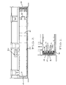
- a short cylindrical body 10 is machined to produce one substantially central externally conical surface 11, preferably surrounded by two concentric truncated external conical surfaces 12, 13. Between each adjacent conical surface 11, 12, 13 there are provided two internal concentric conical surfaces 12a, 13a which are undercut. Said undercut enables each peak 14 to shade each valley or groove base 15. The radius of each valley cannot be infinitely small, and would otherwise be capable of reflecting a small amount of light axially along said sampling tube. Equally importantly, incident axial light becomes trapped within the confines of the inclined surfaces and suffers lossy reflection at least five times before emerging, extremely attenuated, in a non-axial direction. This cannot be achieved with the simple cone or inclined plane designs. In a preferred embodiment the angle of under cut is approximately 5° from the axis of the chamber, and the external cone angle is approximately 30°.
- the sampling tube includes a light source 60 with associated reflector and a lens 40 near a light sensing device 50. If the area adjacent the light source 60 fills with smoke, light impinges on the particles and is transmitted axially along the tube past light baffles 21 to lens 40 and will impinge upon the light sensor 50. Light baffles 21 and 22 are spaced along the tube to catch stray light impinging at various incident angles.
- the absorber 10 with its central cone is positioned on the longitudinal axis aligned with the central axis of the lens and the light sensor. Thus, any light which is directed to the back of the sampling chamber will not be reflected back along the sampling chamber toward the sensor 50. Therefore negligible light is reflected axially along the sampling chamber.
- the absorber is sealingly mounted in the end of the sampling chamber as a press fit. Sealing of the absorber into the chamber is assured by the provision of O-ring seals 16. This facilitates removal of the absorber to allow access to the sampling chamber for servicing purposes while providing a sealing facility for the chamber where it is required to be operated at other than atmospheric pressure.
Landscapes
- Physics & Mathematics (AREA)
- Chemical & Material Sciences (AREA)
- Analytical Chemistry (AREA)
- General Physics & Mathematics (AREA)
- Emergency Management (AREA)
- Business, Economics & Management (AREA)
- General Health & Medical Sciences (AREA)
- Biochemistry (AREA)
- Immunology (AREA)
- Pathology (AREA)
- Life Sciences & Earth Sciences (AREA)
- Health & Medical Sciences (AREA)
- Fire-Detection Mechanisms (AREA)
- Investigating Or Analysing Materials By Optical Means (AREA)
Claims (6)
Applications Claiming Priority (3)
| Application Number | Priority Date | Filing Date | Title |
|---|---|---|---|
| AU821/83 | 1983-08-12 | ||
| AUPG082183 | 1983-08-12 | ||
| AU31842/84A AU575845B2 (en) | 1983-08-12 | 1984-08-10 | Light absorber for smoke detector |
Publications (3)
| Publication Number | Publication Date |
|---|---|
| EP0135361A2 EP0135361A2 (fr) | 1985-03-27 |
| EP0135361A3 EP0135361A3 (en) | 1986-06-11 |
| EP0135361B1 true EP0135361B1 (fr) | 1995-04-26 |
Family
ID=25621948
Family Applications (1)
| Application Number | Title | Priority Date | Filing Date |
|---|---|---|---|
| EP84305513A Expired - Lifetime EP0135361B1 (fr) | 1983-08-12 | 1984-08-13 | Appareil pour la détection de particules en suspension |
Country Status (1)
| Country | Link |
|---|---|
| EP (1) | EP0135361B1 (fr) |
Cited By (2)
| Publication number | Priority date | Publication date | Assignee | Title |
|---|---|---|---|---|
| WO2001071689A1 (fr) * | 2000-03-21 | 2001-09-27 | Vision Systems Ltd | Detecteur de particules |
| EP4078550A1 (fr) * | 2019-12-20 | 2022-10-26 | Siemens Schweiz AG | Chambre de mesure à monter sur une unité de détection de fumée, comportant un piège à lumière selon le principe d'une lentille étagée de fresnel |
Families Citing this family (2)
| Publication number | Priority date | Publication date | Assignee | Title |
|---|---|---|---|---|
| CA2236813C (fr) * | 1997-11-25 | 2005-12-27 | C & K Systems, Inc. | Systeme pour l'absorption et/ou la dispersion de l'irradiation superflue dans un capteur de mouvement optique |
| GB2531495B (en) * | 2014-06-16 | 2017-04-12 | Apollo Fire Detectors Ltd | Smoke detector |
Citations (1)
| Publication number | Priority date | Publication date | Assignee | Title |
|---|---|---|---|---|
| DE2751047B1 (de) * | 1977-11-15 | 1979-03-15 | Maihak Ag | Nichtdispersives Infrarot-Gasanalysengeraet |
Family Cites Families (3)
| Publication number | Priority date | Publication date | Assignee | Title |
|---|---|---|---|---|
| AU8452975A (en) * | 1974-09-09 | 1977-03-10 | Commw Scient Ind Res Org | Smoke detector |
| DE2624977A1 (de) * | 1976-06-03 | 1977-12-08 | Rumpf Hans Prof Dr Ing | Streulichtmesseinrichtung zur ermittlung von partikelgroessenverteilungen und partikelstromdichten disperser phasen in stroemungen |
| US4269510A (en) * | 1978-12-21 | 1981-05-26 | Cerberus Ag | Smoke detector |
-
1984
- 1984-08-13 EP EP84305513A patent/EP0135361B1/fr not_active Expired - Lifetime
Patent Citations (1)
| Publication number | Priority date | Publication date | Assignee | Title |
|---|---|---|---|---|
| DE2751047B1 (de) * | 1977-11-15 | 1979-03-15 | Maihak Ag | Nichtdispersives Infrarot-Gasanalysengeraet |
Cited By (2)
| Publication number | Priority date | Publication date | Assignee | Title |
|---|---|---|---|---|
| WO2001071689A1 (fr) * | 2000-03-21 | 2001-09-27 | Vision Systems Ltd | Detecteur de particules |
| EP4078550A1 (fr) * | 2019-12-20 | 2022-10-26 | Siemens Schweiz AG | Chambre de mesure à monter sur une unité de détection de fumée, comportant un piège à lumière selon le principe d'une lentille étagée de fresnel |
Also Published As
| Publication number | Publication date |
|---|---|
| EP0135361A2 (fr) | 1985-03-27 |
| EP0135361A3 (en) | 1986-06-11 |
Similar Documents
| Publication | Publication Date | Title |
|---|---|---|
| EP0316172B1 (fr) | Analyseur de particules portable | |
| CA1101963A (fr) | Detecteur de fumee a dispersion de rayons lumineux | |
| GB1561421A (en) | Smoke sensor | |
| US4642471A (en) | Scattered radiation smoke detector | |
| EP0571077B1 (fr) | ContrÔleur de pollution d'un fluide | |
| US4405234A (en) | Radiation detection apparatus having refractive light checking feature | |
| CA1257980A (fr) | Methode et dispositif pour determiner le point de trouble d'un carburant diesel | |
| GB2045456A (en) | Detecting particles suspended in a gas | |
| US4607915A (en) | Light absorbers | |
| CN1261972A (zh) | 烟雾报警器 | |
| EP1561125A2 (fr) | Capteur de proximite | |
| CA1109541A (fr) | Detecteur optique de fumee | |
| GB2091873A (en) | Improvements in optical particle detectors | |
| EP0135361B1 (fr) | Appareil pour la détection de particules en suspension | |
| KR890010554A (ko) | 광전입자 검출장치 | |
| US3535531A (en) | High-volume airborne-particle light scattering detector system having rectangularly shaped elongated scanning zone | |
| GB2052732A (en) | Smoke detector apparatus | |
| CN212009807U (zh) | 一种可定向排除凝露干扰的烟雾报警器 | |
| CN111627182B (zh) | 一种带独立式凝露识别仓的烟雾感应器及使用方法 | |
| CN211956682U (zh) | 一种带有凝露识别功能的烟感报警器 | |
| CN111540159B (zh) | 一种可定向排除凝露干扰的烟雾报警器及使用方法 | |
| CN111540158B (zh) | 一种带有凝露识别功能的烟感报警器及使用方法 | |
| RU92011358A (ru) | Датчик дыма | |
| JPS6122278Y2 (fr) | ||
| JPH10253533A (ja) | 被膜反射器付き光検出器 |
Legal Events
| Date | Code | Title | Description |
|---|---|---|---|
| PUAI | Public reference made under article 153(3) epc to a published international application that has entered the european phase |
Free format text: ORIGINAL CODE: 0009012 |
|
| AK | Designated contracting states |
Designated state(s): AT BE CH DE FR GB IT LI LU NL SE |
|
| PUAL | Search report despatched |
Free format text: ORIGINAL CODE: 0009013 |
|
| AK | Designated contracting states |
Kind code of ref document: A3 Designated state(s): AT BE CH DE FR GB IT LI LU NL SE |
|
| 17P | Request for examination filed |
Effective date: 19861204 |
|
| 17Q | First examination report despatched |
Effective date: 19880427 |
|
| RAP1 | Party data changed (applicant data changed or rights of an application transferred) |
Owner name: COLE, MARTIN TERENCE |
|
| RAP1 | Party data changed (applicant data changed or rights of an application transferred) |
Owner name: I.E.I. PTY LTD A.C.N. 053 531 212 |
|
| GRAA | (expected) grant |
Free format text: ORIGINAL CODE: 0009210 |
|
| AK | Designated contracting states |
Kind code of ref document: B1 Designated state(s): AT BE CH DE FR GB IT LI LU NL SE |
|
| PG25 | Lapsed in a contracting state [announced via postgrant information from national office to epo] |
Ref country code: NL Free format text: LAPSE BECAUSE OF NON-PAYMENT OF DUE FEES Effective date: 19950426 Ref country code: LI Effective date: 19950426 Ref country code: IT Free format text: LAPSE BECAUSE OF FAILURE TO SUBMIT A TRANSLATION OF THE DESCRIPTION OR TO PAY THE FEE WITHIN THE PRESCRIBED TIME-LIMIT;WARNING: LAPSES OF ITALIAN PATENTS WITH EFFECTIVE DATE BEFORE 2007 MAY HAVE OCCURRED AT ANY TIME BEFORE 2007. THE CORRECT EFFECTIVE DATE MAY BE DIFFERENT FROM THE ONE RECORDED. Effective date: 19950426 Ref country code: CH Effective date: 19950426 Ref country code: BE Effective date: 19950426 Ref country code: AT Effective date: 19950426 |
|
| REF | Corresponds to: |
Ref document number: 121840 Country of ref document: AT Date of ref document: 19950515 Kind code of ref document: T |
|
| REF | Corresponds to: |
Ref document number: 3486383 Country of ref document: DE Date of ref document: 19950601 |
|
| ET | Fr: translation filed | ||
| PG25 | Lapsed in a contracting state [announced via postgrant information from national office to epo] |
Ref country code: SE Effective date: 19950726 |
|
| REG | Reference to a national code |
Ref country code: CH Ref legal event code: PL |
|
| PG25 | Lapsed in a contracting state [announced via postgrant information from national office to epo] |
Ref country code: LU Free format text: LAPSE BECAUSE OF NON-PAYMENT OF DUE FEES Effective date: 19950831 |
|
| NLV1 | Nl: lapsed or annulled due to failure to fulfill the requirements of art. 29p and 29m of the patents act | ||
| PLBE | No opposition filed within time limit |
Free format text: ORIGINAL CODE: 0009261 |
|
| STAA | Information on the status of an ep patent application or granted ep patent |
Free format text: STATUS: NO OPPOSITION FILED WITHIN TIME LIMIT |
|
| 26N | No opposition filed | ||
| REG | Reference to a national code |
Ref country code: GB Ref legal event code: 732E |
|
| PGFP | Annual fee paid to national office [announced via postgrant information from national office to epo] |
Ref country code: FR Payment date: 19970530 Year of fee payment: 14 |
|
| PGFP | Annual fee paid to national office [announced via postgrant information from national office to epo] |
Ref country code: DE Payment date: 19970624 Year of fee payment: 14 |
|
| PGFP | Annual fee paid to national office [announced via postgrant information from national office to epo] |
Ref country code: GB Payment date: 19970805 Year of fee payment: 14 |
|
| PG25 | Lapsed in a contracting state [announced via postgrant information from national office to epo] |
Ref country code: GB Free format text: LAPSE BECAUSE OF NON-PAYMENT OF DUE FEES Effective date: 19980813 |
|
| GBPC | Gb: european patent ceased through non-payment of renewal fee |
Effective date: 19980813 |
|
| PG25 | Lapsed in a contracting state [announced via postgrant information from national office to epo] |
Ref country code: FR Free format text: LAPSE BECAUSE OF NON-PAYMENT OF DUE FEES Effective date: 19990430 |
|
| PG25 | Lapsed in a contracting state [announced via postgrant information from national office to epo] |
Ref country code: DE Free format text: LAPSE BECAUSE OF NON-PAYMENT OF DUE FEES Effective date: 19990601 |
|
| REG | Reference to a national code |
Ref country code: FR Ref legal event code: ST |