EP0135626B1 - Verfahren zum Sichern von einem Rohr in einer Öffnung - Google Patents
Verfahren zum Sichern von einem Rohr in einer Öffnung Download PDFInfo
- Publication number
- EP0135626B1 EP0135626B1 EP83305692A EP83305692A EP0135626B1 EP 0135626 B1 EP0135626 B1 EP 0135626B1 EP 83305692 A EP83305692 A EP 83305692A EP 83305692 A EP83305692 A EP 83305692A EP 0135626 B1 EP0135626 B1 EP 0135626B1
- Authority
- EP
- European Patent Office
- Prior art keywords
- tube
- plate
- muffler
- collar
- side wall
- Prior art date
- Legal status (The legal status is an assumption and is not a legal conclusion. Google has not performed a legal analysis and makes no representation as to the accuracy of the status listed.)
- Expired
Links
Images


Classifications
-
- F—MECHANICAL ENGINEERING; LIGHTING; HEATING; WEAPONS; BLASTING
- F01—MACHINES OR ENGINES IN GENERAL; ENGINE PLANTS IN GENERAL; STEAM ENGINES
- F01N—GAS-FLOW SILENCERS OR EXHAUST APPARATUS FOR MACHINES OR ENGINES IN GENERAL; GAS-FLOW SILENCERS OR EXHAUST APPARATUS FOR INTERNAL-COMBUSTION ENGINES
- F01N13/00—Exhaust or silencing apparatus characterised by constructional features
- F01N13/18—Construction facilitating manufacture, assembly, or disassembly
- F01N13/1838—Construction facilitating manufacture, assembly, or disassembly characterised by the type of connection between parts of exhaust or silencing apparatus, e.g. between housing and tubes, between tubes and baffles
- F01N13/1844—Mechanical joints
- F01N13/185—Mechanical joints the connection being realised by deforming housing, tube, baffle, plate, or parts thereof
-
- B—PERFORMING OPERATIONS; TRANSPORTING
- B21—MECHANICAL METAL-WORKING WITHOUT ESSENTIALLY REMOVING MATERIAL; PUNCHING METAL
- B21D—WORKING OR PROCESSING OF SHEET METAL OR METAL TUBES, RODS OR PROFILES WITHOUT ESSENTIALLY REMOVING MATERIAL; PUNCHING METAL
- B21D39/00—Application of procedures in order to connect objects or parts, e.g. coating with sheet metal otherwise than by plating; Tube expanders
- B21D39/06—Application of procedures in order to connect objects or parts, e.g. coating with sheet metal otherwise than by plating; Tube expanders of tubes in openings, e.g. rolling-in
-
- F—MECHANICAL ENGINEERING; LIGHTING; HEATING; WEAPONS; BLASTING
- F16—ENGINEERING ELEMENTS AND UNITS; GENERAL MEASURES FOR PRODUCING AND MAINTAINING EFFECTIVE FUNCTIONING OF MACHINES OR INSTALLATIONS; THERMAL INSULATION IN GENERAL
- F16B—DEVICES FOR FASTENING OR SECURING CONSTRUCTIONAL ELEMENTS OR MACHINE PARTS TOGETHER, e.g. NAILS, BOLTS, CIRCLIPS, CLAMPS, CLIPS OR WEDGES; JOINTS OR JOINTING
- F16B17/00—Connecting constructional elements or machine parts by a part of or on one member entering a hole in the other and involving plastic deformation
- F16B17/006—Connecting constructional elements or machine parts by a part of or on one member entering a hole in the other and involving plastic deformation of rods or tubes to sheets or plates
-
- F—MECHANICAL ENGINEERING; LIGHTING; HEATING; WEAPONS; BLASTING
- F16—ENGINEERING ELEMENTS AND UNITS; GENERAL MEASURES FOR PRODUCING AND MAINTAINING EFFECTIVE FUNCTIONING OF MACHINES OR INSTALLATIONS; THERMAL INSULATION IN GENERAL
- F16L—PIPES; JOINTS OR FITTINGS FOR PIPES; SUPPORTS FOR PIPES, CABLES OR PROTECTIVE TUBING; MEANS FOR THERMAL INSULATION IN GENERAL
- F16L41/00—Branching pipes; Joining pipes to walls
- F16L41/08—Joining pipes to walls or pipes, the joined pipe axis being perpendicular to the plane of a wall or to the axis of another pipe
- F16L41/082—Non-disconnectable joints, e.g. soldered, adhesive or caulked joints
-
- F—MECHANICAL ENGINEERING; LIGHTING; HEATING; WEAPONS; BLASTING
- F01—MACHINES OR ENGINES IN GENERAL; ENGINE PLANTS IN GENERAL; STEAM ENGINES
- F01N—GAS-FLOW SILENCERS OR EXHAUST APPARATUS FOR MACHINES OR ENGINES IN GENERAL; GAS-FLOW SILENCERS OR EXHAUST APPARATUS FOR INTERNAL-COMBUSTION ENGINES
- F01N2450/00—Methods or apparatus for fitting, inserting or repairing different elements
- F01N2450/20—Methods or apparatus for fitting, inserting or repairing different elements by mechanical joints, e.g. by deforming housing, tube, baffle plate or parts thereof
Definitions
- This invention relates to a locking member in the form of a collar which can provide a strong mechanical joint between a tube and an apertured plate.
- the construction of muffler assemblies for vehicle silencers has usually required extensive welding between the various components thereof and particularly between the tubes and the baffles.
- This welding is time consuming and tends to assist in the development of corrosion around the weld points. It also tends to result in time in the failure of a percentage of the welds requiring the replacement of the entire silencer.
- the baffles have in the past been generally provided with flanges around the apertures to which the tubes are then inserted. This flange formation also increases the number of operations in the construction of a welded muffler assembly and hence the end cost thereof.
- the present invention has been developed specifically for use in the construction of mufflers but as it will be appreciated hereinafter it could be utilized in numerous other applications and wherever a mechanical joint between a tube and a plate is required.
- a method of securing a tube (5) within an aperture in a plate (6) comprising:
- a muffler including.: a baffle plate (6) having at least one aperture; at least one muffler tube (5) extending into the aperture in the baffle plate (6); and a locking collar (1) formed separately from both the baffle plate (6) and the muffler tube (5), and connecting the muffler tube (5) to the baffle plate (6),'the locking collar (1) including a side wall (3) of substantially circular cross section located between the plate (6) and the tube (5), a first flange (4) extending inwardly from one end of the side wall (3), deformed over an expanded first end (5A) of the tube (5), and capturing the first end (5A) of the tube (5) between the side wall .(3) and the first flange (4) thereby to mechanically join the tube to the locking collar, and a second flange (2) extending outwardly at the opposite end of the side wall (3), seating against the plate (6), and capturing the plate (6) between the second f
- a locking collar 1 has a substantially circular side wall portion 3 with at one end a peripheral inwardly directed flange portion 4 and at an opposite end a peripheral outwardly directed flange portion 2.
- the collar 1 when used in the construction of muffler assemblies would generally be a noncorrosive metal e.g. stainless steel, of suitable gauge e.g. 1 mm or 1.2 mm (20 or 18 bg). Alternatively, it could be of mild steel coated so as to protect against corrosion or plain mild steel but it should be of the same material or have the same coating as the other components to avoid setting up electrolytic action.
- a noncorrosive metal e.g. stainless steel, of suitable gauge e.g. 1 mm or 1.2 mm (20 or 18 bg).
- it could be of mild steel coated so as to protect against corrosion or plain mild steel but it should be of the same material or have the same coating as the other components to avoid setting up electrolytic action.
- the inner and outer flanges 4 and 2 are each shown having an included angle 0 1 and 8 2 which is other than a right angle and may suitably be of the order of 70 degrees.
- FIG 2A the collar 1 is shown positioned at the free end of a tube 5 which has then been inserted into an aperture in a plate 6.
- the flange 2 is shown positioned behind the underside of the plate 6 about the aperture therein, with the flange 4 seating on and extending over the free end of the tube 5.
- Axial pressure by means of a suitable mandrel or other such member inserted into the end of the tube 5 in a direction indicated by arrow A is then applied. This will result in a desired physical joint between the tube 5 and the plate 6 being formed.
- Figure 2B it will be seen that the axial pressure has resulted in the bell-mouthing or expanding of the tube free end 5A.
- the flange 4 has been forced inwardly to form a rim 10 which conforms with and grips the bell-mouthed tube end 5A.
- the side wall 3 is also shown conforming with the exterior surface of the tube end 5A before reaching the lower flange 2. The plate material around the plate aperture is thus trapped between the side wall 3 and the lower flange 2.
- the provision of the included angle 8, defined by the flange 4 with the side wall 3 provides a lead-in for the tube 8.
- the included angle 6 2 defined by the outer flange 2 is however believed to contribute to the resulting joint obtained as described below.
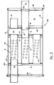
- FIG 3 the present invention as described broadly in Figures 1 and 2 is shown applied to the formation of a muffler-assembly 40.
- the baffle plates 6 have respective muffler tubes 5 secured thereto and there between at their respective ends by locking collars 1A, 1B, 1C and 1A', 1B' and 1C'.
- Such muffler sub-assemblies 40 can then be connected to the end caps as required, either utilizing end connectors to form the desired length of silencer or by adjusting inlet and/or outlet tube lengths and diameters to mate with the assembly.
- the sub-assembly 40 is a tight push-fit into the outer case of barrel so that no welding is necessary.
- the tubes 5 along their respective lengths are shown provided with a plurality of exhaust gas apertures or louvres 13 in known manner.
- the tubes 5 will have mounted at each end respective collars 1 and the collars 1 plus tube ends will then be inserted into respective apertures in the baffle plates 6.
- a pressing operation will then be effected whereby the mechanical joints such as illustrated in Figure 2B will be formed between the tube ends and the baffle plates 6 by means of the respective collars 1 simultaneously.
- the press 11 is shown including lower anvils 14 and 15 on which a sub-assembly such as shown in Figure 3 can be positioned prior to the mechanical joints therein being formed.
- An upper anvil 20 is movable in a vertical plane as illustrated by arrow Z so as to close over the lower anvils 14 and 15.
- the anvil 20 is shown provided with recesses 39 so as to accommodate the curvature of the respective tubes 5.
- the closing of the anvil 20 over the sub-assembly 40 can activate the press sequence wherein anvil 14 can move away from anvil 15 by a small predetermined distance, for example 12.7 mm (0.5"), and can then be locked, in a position whereby the flanges 2 of the collars 1 are supported avoiding compressive stress on the tubes 5.
- a ram 16 can then move towards the anvil 20 until the mandrels 38 engage with the respective collars 1 mounted on the ends of the tubes 5 and to cause axial pressure to be exerted thereon thus forming the joints between the tubes 5 and the baffles 6.
- Spring loaded collars 22 about the respective mandrels 38 can assist in maintaining the collars, tubes and baffle plate in the desired disposition relative one with the other as the joints are formed.
- the resistance offered by the baffle sub-assembly can then cause pressure to be exerted on the bars 18 resulting in the closure of the distance between the end member 17 and the anvil 15.
- Pressure can continue to be exerted on the baffle sub-assembly until its component parts have been physically joined together when the ram 16 can return to a stop on an end member 19.
- the bars 18 can then push the end member 17 away and a spring (not shown) which can be provided under the ram 16 can operate the anvil 14 to retract it back towards the anvil 15 by the aforementioned distance it first moved away.
- the top anvil 20 can then automatically lift up and the finished muffler sub-assembly removed.
- the total time taken may be of the order of 30 seconds.
- the mandrels 23 adjacent the end member 17 are also shown provided with spring loaded collars 22 for the aforementioned purpose.
- the mandrels 22 and 23 are also each shown provided in the respective end members of the press with slots 12 which can enable vertical and horizontal adjustment of the mandrels prior to locking so as to accommodate various locations of apertures in the baffle plates of the sub-assembly.
- press assembly shown in Figure 4 is by way of a very diagrammatic illustration only of a type of press suitable for achieving the desired mechanical joints in a muffler or other required assembly or sub-assembly.
- the muffler 30 is shown having a barrel 31 with respective end caps 27 and 28 secured thereto.
- the inlet tube 26 is shown extending through and secured to an end cap 27 and with a reduced diameter portion 26A extending into the muffler sub-assembly 32 and more particularly into one of the louvred tubes 5 thereof.
- Each of the tubes 5 of the sub-assembly 32 are shown jointed at each end with the respective apertured baffle plates 6 by means of respective collars 1.
- plate 29 defines with one of the baffle plates 6 and an end cap 28 respectively a reversing chamber 33 and a Helmholtz chamber 34.
- a tuning tube 35 is shown extending through and connected with the plate 29 by means of a collar 1.
- the inlet and outlet tubes 26 and 36 are shown connected with the respective end caps 27 and 28 by a non-crimping technique forming joints 24 whilst the end caps 27 and 28 are shown respectively connected with the barrel 31 by means of lock seamed rolled joints 25, no welding being required in this whole assembly.
Landscapes
- Engineering & Computer Science (AREA)
- General Engineering & Computer Science (AREA)
- Mechanical Engineering (AREA)
- Chemical & Material Sciences (AREA)
- Combustion & Propulsion (AREA)
- Exhaust Silencers (AREA)
- Quick-Acting Or Multi-Walled Pipe Joints (AREA)
- Heat Treatment Of Articles (AREA)
- Branch Pipes, Bends, And The Like (AREA)
Claims (7)
Priority Applications (4)
| Application Number | Priority Date | Filing Date | Title |
|---|---|---|---|
| AT83305692T ATE32499T1 (de) | 1983-09-23 | 1983-09-23 | Verfahren zum sichern von einem rohr in einer oeffnung. |
| EP83305692A EP0135626B1 (de) | 1983-09-23 | 1983-09-23 | Verfahren zum Sichern von einem Rohr in einer Öffnung |
| DE8383305692T DE3375688D1 (en) | 1983-09-23 | 1983-09-23 | Method of securing a tube within an aperture |
| SG117/89A SG11789G (en) | 1983-09-23 | 1989-02-20 | Method of securing a tube withn an aperture |
Applications Claiming Priority (1)
| Application Number | Priority Date | Filing Date | Title |
|---|---|---|---|
| EP83305692A EP0135626B1 (de) | 1983-09-23 | 1983-09-23 | Verfahren zum Sichern von einem Rohr in einer Öffnung |
Publications (2)
| Publication Number | Publication Date |
|---|---|
| EP0135626A1 EP0135626A1 (de) | 1985-04-03 |
| EP0135626B1 true EP0135626B1 (de) | 1988-02-17 |
Family
ID=8191295
Family Applications (1)
| Application Number | Title | Priority Date | Filing Date |
|---|---|---|---|
| EP83305692A Expired EP0135626B1 (de) | 1983-09-23 | 1983-09-23 | Verfahren zum Sichern von einem Rohr in einer Öffnung |
Country Status (4)
| Country | Link |
|---|---|
| EP (1) | EP0135626B1 (de) |
| AT (1) | ATE32499T1 (de) |
| DE (1) | DE3375688D1 (de) |
| SG (1) | SG11789G (de) |
Families Citing this family (2)
| Publication number | Priority date | Publication date | Assignee | Title |
|---|---|---|---|---|
| UY25028A1 (es) * | 1997-06-16 | 1998-11-20 | Delaroy Sdn Bhd | Cierre de extremo de tubo |
| DE102007060398B4 (de) * | 2007-12-14 | 2016-10-06 | GM Global Technology Operations LLC (n. d. Ges. d. Staates Delaware) | Auspuff eines Kraftfahrzeugs |
Family Cites Families (2)
| Publication number | Priority date | Publication date | Assignee | Title |
|---|---|---|---|---|
| FR1564563A (de) * | 1968-01-23 | 1969-04-25 | ||
| US4192531A (en) * | 1978-05-22 | 1980-03-11 | Arvin Industries, Inc. | Tube-to-plate connection |
-
1983
- 1983-09-23 DE DE8383305692T patent/DE3375688D1/de not_active Expired
- 1983-09-23 EP EP83305692A patent/EP0135626B1/de not_active Expired
- 1983-09-23 AT AT83305692T patent/ATE32499T1/de not_active IP Right Cessation
-
1989
- 1989-02-20 SG SG117/89A patent/SG11789G/en unknown
Also Published As
| Publication number | Publication date |
|---|---|
| SG11789G (en) | 1989-07-07 |
| DE3375688D1 (en) | 1988-03-24 |
| ATE32499T1 (de) | 1988-03-15 |
| EP0135626A1 (de) | 1985-04-03 |
Similar Documents
| Publication | Publication Date | Title |
|---|---|---|
| KR0166400B1 (ko) | 유체 안내부재용 접속기 조립체와 이러한 조립체의 슬리이브 커플링, 그리고 유체 안내 부재를 연결시키기 위한 접속기의 제조 방법 | |
| US5487219A (en) | Method of manufacturing engine cradles | |
| US6742258B2 (en) | Method of hydroforming articles and the articles formed thereby | |
| US5170557A (en) | Method of forming a double wall, air gap exhaust duct component | |
| US3689972A (en) | Method of fabricating a heat exchanger | |
| US6654995B1 (en) | Method for joining tubular members | |
| US5477015A (en) | Vehicular muffler with improved mechanical lock joints | |
| US6343417B1 (en) | Process of manufacturing an air-gap-insulating exhaust elbow of a vehicle exhaust system | |
| US5559308A (en) | Perpendicularly joined structure with thin-walled plates and thin-walled tubes and the method of manufacture | |
| DE19752772C2 (de) | Verfahren zur Herstellung eines mit einem Abzweigstutzen versehenen luftspaltisolierten Abgasrohres | |
| US20020162224A1 (en) | Hydroformed vehicle frame assembly and method | |
| US4576247A (en) | Locking member | |
| JP3449897B2 (ja) | 熱交換器及びその製造方法 | |
| EP0135626A1 (de) | Verfahren zum Sichern von einem Rohr in einer Öffnung | |
| JPH1085944A (ja) | 内部高圧成形のためのプレフォームを形成する方法及びこの方法によって製作されたプレフォーム | |
| JPH07223030A (ja) | 管と板材の接合装置 | |
| CA1212630A (en) | Locking member | |
| US6532639B2 (en) | Hydroformed tubular structures and methods of making | |
| EP0737818A1 (de) | Niet | |
| US5579577A (en) | Improved method for fabricating a muffler | |
| NZ198127A (en) | Securing tube in plate aperture with flanged collar | |
| JPS6334757Y2 (de) | ||
| EP1320698B1 (de) | Verfahren und vorrichtung zur erzeugung einer gefalzten verbindung zwischen einem rohrförmigen körper und einem deckel | |
| US5979202A (en) | Method and apparatus for making pipe line steel grooved-end fittings | |
| JP3801586B2 (ja) | 角形鋼管柱の製造方法 |
Legal Events
| Date | Code | Title | Description |
|---|---|---|---|
| PUAI | Public reference made under article 153(3) epc to a published international application that has entered the european phase |
Free format text: ORIGINAL CODE: 0009012 |
|
| 17P | Request for examination filed |
Effective date: 19841003 |
|
| AK | Designated contracting states |
Designated state(s): AT BE CH DE FR GB IT LI NL SE |
|
| RAP1 | Party data changed (applicant data changed or rights of an application transferred) |
Owner name: THORPE, DENIS |
|
| RIN1 | Information on inventor provided before grant (corrected) |
Inventor name: THORPE, DENIS |
|
| ITF | It: translation for a ep patent filed | ||
| GRAA | (expected) grant |
Free format text: ORIGINAL CODE: 0009210 |
|
| AK | Designated contracting states |
Kind code of ref document: B1 Designated state(s): AT BE CH DE FR GB IT LI NL SE |
|
| REF | Corresponds to: |
Ref document number: 32499 Country of ref document: AT Date of ref document: 19880315 Kind code of ref document: T |
|
| REF | Corresponds to: |
Ref document number: 3375688 Country of ref document: DE Date of ref document: 19880324 |
|
| ET | Fr: translation filed | ||
| PLBE | No opposition filed within time limit |
Free format text: ORIGINAL CODE: 0009261 |
|
| STAA | Information on the status of an ep patent application or granted ep patent |
Free format text: STATUS: NO OPPOSITION FILED WITHIN TIME LIMIT |
|
| 26N | No opposition filed | ||
| ITTA | It: last paid annual fee | ||
| EAL | Se: european patent in force in sweden |
Ref document number: 83305692.2 |
|
| PGFP | Annual fee paid to national office [announced via postgrant information from national office to epo] |
Ref country code: SE Payment date: 19980904 Year of fee payment: 16 |
|
| PGFP | Annual fee paid to national office [announced via postgrant information from national office to epo] |
Ref country code: FR Payment date: 19980909 Year of fee payment: 16 |
|
| PGFP | Annual fee paid to national office [announced via postgrant information from national office to epo] |
Ref country code: AT Payment date: 19980914 Year of fee payment: 16 |
|
| PGFP | Annual fee paid to national office [announced via postgrant information from national office to epo] |
Ref country code: GB Payment date: 19980916 Year of fee payment: 16 |
|
| PGFP | Annual fee paid to national office [announced via postgrant information from national office to epo] |
Ref country code: NL Payment date: 19980929 Year of fee payment: 16 |
|
| PGFP | Annual fee paid to national office [announced via postgrant information from national office to epo] |
Ref country code: BE Payment date: 19981118 Year of fee payment: 16 |
|
| PG25 | Lapsed in a contracting state [announced via postgrant information from national office to epo] |
Ref country code: GB Free format text: LAPSE BECAUSE OF NON-PAYMENT OF DUE FEES Effective date: 19990923 Ref country code: AT Free format text: LAPSE BECAUSE OF NON-PAYMENT OF DUE FEES Effective date: 19990923 |
|
| PG25 | Lapsed in a contracting state [announced via postgrant information from national office to epo] |
Ref country code: SE Free format text: THE PATENT HAS BEEN ANNULLED BY A DECISION OF A NATIONAL AUTHORITY Effective date: 19990929 |
|
| PG25 | Lapsed in a contracting state [announced via postgrant information from national office to epo] |
Ref country code: BE Free format text: LAPSE BECAUSE OF NON-PAYMENT OF DUE FEES Effective date: 19990930 |
|
| BERE | Be: lapsed |
Owner name: THORPE DENIS Effective date: 19990930 |
|
| PG25 | Lapsed in a contracting state [announced via postgrant information from national office to epo] |
Ref country code: NL Free format text: LAPSE BECAUSE OF NON-PAYMENT OF DUE FEES Effective date: 20000401 |
|
| GBPC | Gb: european patent ceased through non-payment of renewal fee |
Effective date: 19990923 |
|
| EUG | Se: european patent has lapsed |
Ref document number: 83305692.2 |
|
| REG | Reference to a national code |
Ref country code: CH Ref legal event code: PL |
|
| PG25 | Lapsed in a contracting state [announced via postgrant information from national office to epo] |
Ref country code: FR Free format text: LAPSE BECAUSE OF NON-PAYMENT OF DUE FEES Effective date: 20000531 |
|
| NLV4 | Nl: lapsed or anulled due to non-payment of the annual fee |
Effective date: 20000401 |
|
| PGFP | Annual fee paid to national office [announced via postgrant information from national office to epo] |
Ref country code: CH Payment date: 20000607 Year of fee payment: 17 |
|
| REG | Reference to a national code |
Ref country code: CH Ref legal event code: AEN Free format text: LE BREVET A ETE REACTIVE SELON LA DEMANDE DE POURSUITE DE LA PROCEDURE DU 06.06.2000 |
|
| REG | Reference to a national code |
Ref country code: FR Ref legal event code: ST |
|
| PG25 | Lapsed in a contracting state [announced via postgrant information from national office to epo] |
Ref country code: LI Free format text: LAPSE BECAUSE OF NON-PAYMENT OF DUE FEES Effective date: 20000930 Ref country code: CH Free format text: LAPSE BECAUSE OF NON-PAYMENT OF DUE FEES Effective date: 20000930 |
|
| REG | Reference to a national code |
Ref country code: CH Ref legal event code: PL |
|
| PGFP | Annual fee paid to national office [announced via postgrant information from national office to epo] |
Ref country code: DE Payment date: 20021107 Year of fee payment: 20 |