EP0135687B1 - Electrode métallique pour dégagement gazeux - Google Patents
Electrode métallique pour dégagement gazeux Download PDFInfo
- Publication number
- EP0135687B1 EP0135687B1 EP84107873A EP84107873A EP0135687B1 EP 0135687 B1 EP0135687 B1 EP 0135687B1 EP 84107873 A EP84107873 A EP 84107873A EP 84107873 A EP84107873 A EP 84107873A EP 0135687 B1 EP0135687 B1 EP 0135687B1
- Authority
- EP
- European Patent Office
- Prior art keywords
- profiles
- electrode
- curvature
- gas
- metal electrode
- Prior art date
- Legal status (The legal status is an assumption and is not a legal conclusion. Google has not performed a legal analysis and makes no representation as to the accuracy of the status listed.)
- Expired
Links
Images
Classifications
-
- C—CHEMISTRY; METALLURGY
- C25—ELECTROLYTIC OR ELECTROPHORETIC PROCESSES; APPARATUS THEREFOR
- C25B—ELECTROLYTIC OR ELECTROPHORETIC PROCESSES FOR THE PRODUCTION OF COMPOUNDS OR NON-METALS; APPARATUS THEREFOR
- C25B11/00—Electrodes; Manufacture thereof not otherwise provided for
- C25B11/02—Electrodes; Manufacture thereof not otherwise provided for characterised by shape or form
Definitions
- the present invention relates to a gas-evolving metal electrode, e.g. can be used in particular as an anode in amalgam cells for chlor-alkali electrolysis.
- the use of titanium as the electrode base material allows a large number of different geometrical designs in comparison to graphite in order to fulfill the required function as a gas-generating electrode.
- the production of very flat electrode surfaces (+ 1 mm difference / m 2 electrode surface) has become possible. This in turn allows the distance from the anode to the cathode to be significantly reduced.
- the electrolyte solution in the case of chloralkali electrolysis the NaCI solution, has an electrical resistance, the aim is to reduce the voltage or energy losses caused thereby to a minimum by keeping the distance between the electrodes as small as possible.
- OE-AS 20 41 250 an electrode construction is described in which the working electrode surface, that of the cathode, e.g. in chlorine production using the amalgam process, the mercury cathode, made of expanded metal, perforated sheet metal, wire mesh or the like. is formed.
- a U-shaped conductor rail is used for uniform current distribution, which must also give the expanded metal the necessary mechanical rigidity in order to achieve the required planarity. It is easy to see that the production of such a conductor rail is very problematic, since titanium sheets have to be pressed into a U-shape and titanium tends to “spring back” after such a pressing process.
- notches have to be incorporated into this conductor rail , which reduce the stresses that occur when the expanded metal is welded to the rail, and also allow subsequent correction of the working surface of the anode in order to achieve a better planarity of the electrode surface
- the gas bubbles formed are now discharged upwards through the openings in the expanded metal, perforated plate, etc.
- openings must therefore also be worked into the relatively large conductor rail
- Conductor rails can also be fixed with stable cross struts.
- the titanium sheathing of the aluminum must be absolutely tight at all points, in particular also at the weld seams, since with the slightest damage to the titanium sheath, the electrode is rapidly destroyed by the anodic dissolution of the aluminum which takes place in the presence of chloride.
- US Pat. No. 4,055,847 describes a complicated structure for achieving the necessary strength of the electrode surface and for achieving a good current distribution. It consists of a spider-shaped power distribution system, in which additional support ribs are required. As stated in the patent specification, melting and casting processes are necessary to produce the corresponding structures. However, as is generally known, these are complex and expensive in the processing of metals, in particular titanium or valve metals, since valve metals can only be melted in an argon atmosphere with a strict exclusion of air for metallurgical reasons. Another possible solution is shown in DE-OS 29 49 495. However, this construction also requires a primary and secondary power distribution system, which - analogous to that of DE-OS 1814 567 - require high manufacturing and material costs. Due to the relatively open construction of this system from flat profiles, however, gas bubble tearing and mass transfer on the electrode surface are to be improved.
- DE-OS 30 08 116 describes an electrode construction which has only a primary distribution system, but which is also relatively complex.
- the oval profiles used here are created by flattening the round bars. This should achieve a ratio of working to projected electrode area of> 1.
- no attention is paid here cf. J. Cramer, Chem. Ing. Techn. 52, 1980, pp. 48-51 that the solution to be electrolyzed opposes the passage of the electric current, so that the electrode surfaces are all the less to the course of the electrolysis reaction, ie Gas evolution contribute the further away they are from the counter electrode.
- the reason for this is the fact that the streamlines are looking for the shortest possible route as they pass through the solution to be electrolyzed.
- German utility model 72 07 894 describes a gas-developing electrode which consists of a plate which is interspersed with channels which widen near and to a surface of the electrode. These channels can be continuously conical or venturi-like. This is intended to achieve an improved electrolyte circulation. Apart from the fact that this electrode can only be produced with complex manufacturing technology, this electrode has not found any technical use, since plate-shaped electrodes in particular have disadvantages with regard to gas removal.
- a gas-developing metal electrode for electrolysis cells in particular anode for amalgam cells for chloralkali electrolysis, which consists of profiles arranged parallel to one another in a horizontal plane, the effective electrode surface facing the counterelectrode being curved and the profiles having a transverse profile with it a power supply provided power supply are connected to each other, which is characterized in that the curvature of the effective electrode surface in the area of the gaps into one with a smaller radius (r) passes, the radius (R) determining the curvature of the effective electrode surface being from 7 to 180 mm and the smaller radius (r) being 0.5 to 4 mm, and the profiles being closed off at the top by two side surfaces which emerge tangentially from the curvature (22, 25), which form an angle (alpha) of 20 to 120 ° at their intersection.
- Solid or hollow profiles can be used as profiles for the electrodes according to the invention.
- full profiles more titanium is required than with hollow profiles, but this disadvantage is offset by the advantage that the resistance is reduced and the voltage drop is reduced.
- full profiles are easier to process.
- the effective electrode area i.e. the surface which can be projected onto the counterelectrode is curved in such a way that the curvature increases from the center towards the edges.
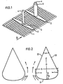
- FIG. 1 is a perspective view
- FIG. 2 in which two profiles are shown enlarged from viewing direction X.
- the effective electrode surface consists of profiles arranged parallel to each other.
- the mechanical and electrical connection of these electrode profiles to one another is carried out by welding with one or more titanium webs (2) which have a shape specially developed for the purpose described. Titanium bodies (5) with an internal thread are attached to these webs.
- the internal thread serves to receive a power supply (4), e.g. a copper bolt. If necessary, this can be protected from the electrolyte solution (and thus anodic dissolution) by a welded-on titanium tube (5).
- the power supply to the individual electrode profiles takes place exclusively through a simple primary conductor system made of titanium webs (2). This is easy to manufacture from commercially available titanium sheets of appropriate thickness (matched to the current load) by simply punching them out.
- FIG. 2 two hollow electrode profiles according to the invention, according to viewing direction X from FIG. 1, are shown schematically, enlarged compared to FIG.
- the work surface 21, i.e. the surface which can be projected onto the counterelectrode is curved according to the invention in such a way that the curvature on the sides, i.e. to the neighboring profile or to the cell wall becomes stronger.
- the curvature is determined by the radius R and the two smaller radii r.
- the hollow profile is closed at the top by the two meeting side surfaces 22 and 25, which are continued tangentially from the curved working surface.
- the cross section of the gap zone between two profiles is given the profile of a nozzle-shaped rounded inlet zone and a calming zone which widens upward like a diffuser.
- the gas bubbles formed on the work surface move towards the edges of the profiles and, due to the intensifying curvature, experience a desired uniform acceleration in contrast to an abrupt tearing off of the gas bubbles on an edge-shaped profile, which results in a higher pressure loss connected is.
- the gas is brought to the speed required to pass the narrowest point of the gap between two profiles with a minimal pressure loss. Due to the lower pressure drop, the gas bubbles reach a higher speed, which entrains a larger amount of liquid.
- the profiles should have certain geometric dimensions have, which are selected depending on the cell conditions.
- the work surface has less curvature in the middle than at the edges.
- the curvature in the central part is determined by a circular line whose radius R is 7-180 mm, preferably 15 to 25 mm, while on both sides the curvature becomes stronger and in a circular line with a radius r of 0.5 to 4 mm passes.
- the two radii should be chosen so that R / r i: 5.
- the inventive design of the work surface ensures that, due to the relatively large radius of the circular line in the central region, an almost optimal, uniform distance of the work surface from the counter-cathode is ensured, the relatively small curvature of which, however, is already sufficient for rapid removal of the gas bubbles formed. Due to the stronger rounding at the transition of the work surface into the tangential side surfaces, edges are avoided at this point, which, as is known, are subject to increased wear.
- the height of the circular arc results (ie the greatest distance between the web width S and the working surface 21), which, however, should meet the condition that is from 5 to 1800.
- the inclination of the side surfaces can also be varied within wide limits. This inclination is determined by the angle with which they meet and which can expediently be from 20 ° to 120 °.
- the technical outlay for producing the metal electrodes according to the invention is low.
- the individual electrode profiles (5) need only be welded continuously to the distributor webs (2). Notches into which the profiles are inserted can be incorporated into these webs for better fixation.
- the relatively long weld seam ensures good current transfer from the distributor web to the profiles.
- the electrode construction according to the invention is characterized by an extraordinarily simple structure, its mechanical strength is excellent, essentially also due to the cross-sectional shape of the profiles according to the invention.
- the electrodes are also very easy to repair. If a profile is damaged, e.g. by short-circuiting, the respective electrode profiles can easily be exchanged individually or brought to the required planarity by corresponding messages.
- the claimed electrode From the description of the claimed electrode it also follows that only the actually effective surface of the electrode base body has to be provided with an active layer, since here there is a construction in which different partial areas of the profiles are each optimized with regard to the task to be performed.
- the side opposite the counterelectrode is so designed that the working electrode surface can optimally fulfill its function in the electrolysis process.
- the other sections of the electrode profile are optimized according to hydrodynamic criteria and simple manufacture.
- the construction is therefore very suitable for applying the activation solution by dipping, rolling or brushing. Since it is relatively easy to coat only the working electrode surface (which is desirable but not a requirement), the amount of activation solution required is reduced to a minimum. This is particularly advantageous when using activation solutions which contain expensive noble metals or noble metal compounds, for example in the case of the known Ru0 2- containing active layers for anodic chlorine deposition.
- this construction can be coated very well with the aid of spraying processes - in particular thermal spraying processes - since the working electrode surface has no sharp edges and since it is not necessary to coat side surfaces which are difficult to access.
Landscapes
- Chemical & Material Sciences (AREA)
- Engineering & Computer Science (AREA)
- Chemical Kinetics & Catalysis (AREA)
- Electrochemistry (AREA)
- Materials Engineering (AREA)
- Metallurgy (AREA)
- Organic Chemistry (AREA)
- Electrodes For Compound Or Non-Metal Manufacture (AREA)
Claims (4)

Applications Claiming Priority (4)
| Application Number | Priority Date | Filing Date | Title |
|---|---|---|---|
| DE19833325187 DE3325187A1 (de) | 1983-07-13 | 1983-07-13 | Gasentwickelnde metallelektrode |
| DE3325187 | 1983-07-13 | ||
| DE19833345530 DE3345530A1 (de) | 1983-07-13 | 1983-12-16 | Gasentwickelnde metallelektrode fuer elektrolysezellen |
| DE3345530 | 1983-12-16 |
Publications (2)
| Publication Number | Publication Date |
|---|---|
| EP0135687A1 EP0135687A1 (fr) | 1985-04-03 |
| EP0135687B1 true EP0135687B1 (fr) | 1986-10-15 |
Family
ID=25812249
Family Applications (1)
| Application Number | Title | Priority Date | Filing Date |
|---|---|---|---|
| EP84107873A Expired EP0135687B1 (fr) | 1983-07-13 | 1984-07-05 | Electrode métallique pour dégagement gazeux |
Country Status (3)
| Country | Link |
|---|---|
| US (1) | US4557818A (fr) |
| EP (1) | EP0135687B1 (fr) |
| DE (2) | DE3345530A1 (fr) |
Families Citing this family (9)
| Publication number | Priority date | Publication date | Assignee | Title |
|---|---|---|---|---|
| US5087344A (en) * | 1990-09-26 | 1992-02-11 | Heraeus Elektroden Gmbh | Electrolysis cell for gas-evolving electrolytic processes |
| DE4306889C1 (de) * | 1993-03-05 | 1994-08-18 | Heraeus Elektrochemie | Elektrodenanordnung für gasbildende elektrolytische Prozesse in Membran-Zellen und deren Verwendung |
| DE4419277C2 (de) * | 1994-06-01 | 1998-07-02 | Heraeus Elektrochemie | Elektrolysezellen-Elektrode |
| KR970064007U (ko) * | 1996-05-28 | 1997-12-11 | 카 오디오의 탈거 구조 | |
| US5849164A (en) * | 1996-06-27 | 1998-12-15 | Eltech Systems Corporation | Cell with blade electrodes and recirculation chamber |
| ES2215603T3 (es) * | 1999-01-08 | 2004-10-16 | Moltech Invent S.A. | Celda para electrolisis de aluminio con anodos generadores de oxigeno. |
| ATE382722T1 (de) * | 2001-07-13 | 2008-01-15 | Moltech Invent Sa | Anodenstrukturen auf der basis von legierungen für die herstellung von aluminium |
| US20080041729A1 (en) * | 2004-11-05 | 2008-02-21 | Vittorio De Nora | Aluminium Electrowinning With Enhanced Electrolyte Circulation |
| DE102006054442A1 (de) * | 2006-11-16 | 2008-05-21 | Hydrodivide Ag | Elektrode und ihre Verwendung |
Family Cites Families (11)
| Publication number | Priority date | Publication date | Assignee | Title |
|---|---|---|---|---|
| US3409533A (en) * | 1964-03-23 | 1968-11-05 | Asahi Chemical Ind | Mercury-method cell for alkali chloride electrolysis |
| GB1068992A (en) * | 1964-03-31 | 1967-05-17 | Asahi Chemical Ind | Anode assembly |
| US3616445A (en) * | 1967-12-14 | 1971-10-26 | Electronor Corp | Titanium or tantalum base electrodes with applied titanium or tantalum oxide face activated with noble metals or noble metal oxides |
| BE754741A (fr) * | 1969-08-14 | 1971-01-18 | Burndy Corp | Amortisseur de cable pour des lignes de transmission |
| BE755592A (fr) * | 1969-09-02 | 1971-03-02 | Ici Ltd | Assemblage anodique |
| US3795603A (en) * | 1971-08-26 | 1974-03-05 | Uhde Gmbh | Apparatus for the electrolysis of alkali metal chloride solutions with mercury cathode |
| DE7207894U (de) * | 1972-03-02 | 1972-11-30 | Metallges Ag | Elektrode, insbesondere anode |
| US4033847A (en) * | 1973-11-05 | 1977-07-05 | Olin Corporation | Metal anode assembly |
| SU567771A1 (ru) * | 1975-04-14 | 1977-08-05 | Предприятие П/Я В-2287 | Диафрагменный электролизер дл получени хлора и щелочи |
| DE2721958A1 (de) * | 1977-05-14 | 1978-11-16 | Hoechst Ag | Metallelektrode fuer elektrolyseapparate zum elektrolytischen herstellen von chlor |
| DE3008116A1 (de) * | 1980-03-03 | 1981-09-17 | Conradty GmbH & Co Metallelektroden KG, 8505 Röthenbach | Gasentwickelnde metallelektrode fuer elektrochemische prozesse |
-
1983
- 1983-12-16 DE DE19833345530 patent/DE3345530A1/de not_active Withdrawn
-
1984
- 1984-07-05 EP EP84107873A patent/EP0135687B1/fr not_active Expired
- 1984-07-05 DE DE8484107873T patent/DE3460986D1/de not_active Expired
- 1984-07-12 US US06/630,184 patent/US4557818A/en not_active Expired - Lifetime
Also Published As
| Publication number | Publication date |
|---|---|
| DE3460986D1 (en) | 1986-11-20 |
| US4557818A (en) | 1985-12-10 |
| EP0135687A1 (fr) | 1985-04-03 |
| DE3345530A1 (de) | 1985-06-27 |
Similar Documents
| Publication | Publication Date | Title |
|---|---|---|
| DD243516A5 (de) | Monopolare und bipolara chlorzellen und elektrodenstrukturen fuer diese | |
| DE2262173C3 (fr) | ||
| DE2231196A1 (de) | Anodensatz fuer elektrolytische zellen | |
| EP0135687B1 (fr) | Electrode métallique pour dégagement gazeux | |
| DE69213362T2 (de) | Elektrolyseur und Herstellung davon | |
| DE2135873B2 (de) | Zellenoberteil für Amalgamhochlastzellen | |
| EP0089475A1 (fr) | Anode revêtue à base de métal soupape pour l'obtention électrolytique de métaux ou oxydes de métaux | |
| DE2923818C2 (fr) | ||
| EP0479840A1 (fr) | Cellule electrolytique pour processus electrolytiques degageant du gaz. | |
| DE3808495C2 (fr) | ||
| DE2125941C3 (de) | Bipolare Einheit und damit aufgebaute elektrolytische Zelle | |
| DE1467075B2 (de) | Anode zur elektrolytischen Herstellung von Chlor | |
| EP0035131B1 (fr) | Electrode métallique dégageant du gaz pour procédés électrochimiques | |
| EP0753604B1 (fr) | Anode pour l'obtention électrolytique de métaux | |
| EP0274138A1 (fr) | Agencement d'électrode, pour électrolyseurs produisant des gaz, présentant des plaques d'électrode disposées verticalement | |
| DE2845832A1 (de) | Vorrichtung zur diaphragma-elektrolyse | |
| DE2949495A1 (de) | Elektrode fuer elektrolysezellen | |
| DE2909640A1 (de) | Elektrolyseapparat | |
| DE3239535C2 (de) | Verfahren zur Herstellung einer bipolaren Elektrode | |
| DE3406797A1 (de) | Beschichtete ventilmetallanode zur elektrolytischen gewinnung von metallen oder metalloxiden | |
| DD242641A5 (de) | Vollstaendig aus teilen zusammengesetzte elektrochemische zelle | |
| DE3325187A1 (de) | Gasentwickelnde metallelektrode | |
| DE3005795C2 (de) | Beschichtete Metallanode zur elektrolytischen Gewinnung von Metallen | |
| DE69203267T2 (de) | Elektrischer Leiter, Verfahren zur Herstellung eines elektrischen Leiters und Elektrode für Elektrolysezelle. | |
| DE3941056C2 (de) | Verfahren zur Herstellung einer elektrisch gutleitenden Verbindung durch Reibschweißung und Stromleiter |
Legal Events
| Date | Code | Title | Description |
|---|---|---|---|
| PUAI | Public reference made under article 153(3) epc to a published international application that has entered the european phase |
Free format text: ORIGINAL CODE: 0009012 |
|
| AK | Designated contracting states |
Designated state(s): BE DE FR GB IT NL SE |
|
| 17P | Request for examination filed |
Effective date: 19850329 |
|
| 17Q | First examination report despatched |
Effective date: 19860227 |
|
| GRAA | (expected) grant |
Free format text: ORIGINAL CODE: 0009210 |
|
| AK | Designated contracting states |
Kind code of ref document: B1 Designated state(s): BE DE FR GB IT NL SE |
|
| ITF | It: translation for a ep patent filed | ||
| REF | Corresponds to: |
Ref document number: 3460986 Country of ref document: DE Date of ref document: 19861120 |
|
| ET | Fr: translation filed | ||
| R20 | Corrections of a patent specification |
Effective date: 19870119 |
|
| PLBE | No opposition filed within time limit |
Free format text: ORIGINAL CODE: 0009261 |
|
| STAA | Information on the status of an ep patent application or granted ep patent |
Free format text: STATUS: NO OPPOSITION FILED WITHIN TIME LIMIT |
|
| 26N | No opposition filed | ||
| ITTA | It: last paid annual fee | ||
| EAL | Se: european patent in force in sweden |
Ref document number: 84107873.6 |
|
| PGFP | Annual fee paid to national office [announced via postgrant information from national office to epo] |
Ref country code: FR Payment date: 20000626 Year of fee payment: 17 |
|
| PGFP | Annual fee paid to national office [announced via postgrant information from national office to epo] |
Ref country code: SE Payment date: 20000627 Year of fee payment: 17 Ref country code: NL Payment date: 20000627 Year of fee payment: 17 |
|
| PGFP | Annual fee paid to national office [announced via postgrant information from national office to epo] |
Ref country code: GB Payment date: 20000703 Year of fee payment: 17 |
|
| PGFP | Annual fee paid to national office [announced via postgrant information from national office to epo] |
Ref country code: DE Payment date: 20000714 Year of fee payment: 17 |
|
| PGFP | Annual fee paid to national office [announced via postgrant information from national office to epo] |
Ref country code: BE Payment date: 20000817 Year of fee payment: 17 |
|
| PG25 | Lapsed in a contracting state [announced via postgrant information from national office to epo] |
Ref country code: GB Free format text: LAPSE BECAUSE OF NON-PAYMENT OF DUE FEES Effective date: 20010705 |
|
| PG25 | Lapsed in a contracting state [announced via postgrant information from national office to epo] |
Ref country code: SE Free format text: LAPSE BECAUSE OF NON-PAYMENT OF DUE FEES Effective date: 20010706 |
|
| PG25 | Lapsed in a contracting state [announced via postgrant information from national office to epo] |
Ref country code: DE Free format text: LAPSE BECAUSE OF THE APPLICANT RENOUNCES Effective date: 20010714 |
|
| PG25 | Lapsed in a contracting state [announced via postgrant information from national office to epo] |
Ref country code: BE Free format text: LAPSE BECAUSE OF NON-PAYMENT OF DUE FEES Effective date: 20010731 |
|
| BERE | Be: lapsed |
Owner name: BASF A.G. Effective date: 20010731 |
|
| PG25 | Lapsed in a contracting state [announced via postgrant information from national office to epo] |
Ref country code: NL Free format text: LAPSE BECAUSE OF NON-PAYMENT OF DUE FEES Effective date: 20020201 |
|
| GBPC | Gb: european patent ceased through non-payment of renewal fee |
Effective date: 20010705 |
|
| EUG | Se: european patent has lapsed |
Ref document number: 84107873.6 |
|
| PG25 | Lapsed in a contracting state [announced via postgrant information from national office to epo] |
Ref country code: FR Free format text: LAPSE BECAUSE OF NON-PAYMENT OF DUE FEES Effective date: 20020329 |
|
| NLV4 | Nl: lapsed or anulled due to non-payment of the annual fee |
Effective date: 20020201 |
|
| REG | Reference to a national code |
Ref country code: FR Ref legal event code: ST |