EP0135708A2 - Verfahren zur Herstellung eines thermoplastischen Verbundkörpers - Google Patents
Verfahren zur Herstellung eines thermoplastischen Verbundkörpers Download PDFInfo
- Publication number
- EP0135708A2 EP0135708A2 EP84108839A EP84108839A EP0135708A2 EP 0135708 A2 EP0135708 A2 EP 0135708A2 EP 84108839 A EP84108839 A EP 84108839A EP 84108839 A EP84108839 A EP 84108839A EP 0135708 A2 EP0135708 A2 EP 0135708A2
- Authority
- EP
- European Patent Office
- Prior art keywords
- tube
- tubes
- tubular elements
- composite
- metal layers
- Prior art date
- Legal status (The legal status is an assumption and is not a legal conclusion. Google has not performed a legal analysis and makes no representation as to the accuracy of the status listed.)
- Granted
Links
Images

Classifications
-
- B—PERFORMING OPERATIONS; TRANSPORTING
- B32—LAYERED PRODUCTS
- B32B—LAYERED PRODUCTS, i.e. PRODUCTS BUILT-UP OF STRATA OF FLAT OR NON-FLAT, e.g. CELLULAR OR HONEYCOMB, FORM
- B32B3/00—Layered products comprising a layer with external or internal discontinuities or unevennesses, or a layer of non-planar shape; Layered products comprising a layer having particular features of form
- B32B3/10—Layered products comprising a layer with external or internal discontinuities or unevennesses, or a layer of non-planar shape; Layered products comprising a layer having particular features of form characterised by a discontinuous layer, i.e. formed of separate pieces of material
- B32B3/18—Layered products comprising a layer with external or internal discontinuities or unevennesses, or a layer of non-planar shape; Layered products comprising a layer having particular features of form characterised by a discontinuous layer, i.e. formed of separate pieces of material characterised by an internal layer formed of separate pieces of material which are juxtaposed side-by-side
- B32B3/20—Layered products comprising a layer with external or internal discontinuities or unevennesses, or a layer of non-planar shape; Layered products comprising a layer having particular features of form characterised by a discontinuous layer, i.e. formed of separate pieces of material characterised by an internal layer formed of separate pieces of material which are juxtaposed side-by-side of hollow pieces, e.g. tubes; of pieces with channels or cavities
-
- B—PERFORMING OPERATIONS; TRANSPORTING
- B29—WORKING OF PLASTICS; WORKING OF SUBSTANCES IN A PLASTIC STATE IN GENERAL
- B29D—PRODUCING PARTICULAR ARTICLES FROM PLASTICS OR FROM SUBSTANCES IN A PLASTIC STATE
- B29D24/00—Producing articles with hollow walls
- B29D24/002—Producing articles with hollow walls formed with structures, e.g. cores placed between two plates or sheets, e.g. partially filled
- B29D24/005—Producing articles with hollow walls formed with structures, e.g. cores placed between two plates or sheets, e.g. partially filled the structure having joined ribs, e.g. honeycomb
- B29D24/007—Producing articles with hollow walls formed with structures, e.g. cores placed between two plates or sheets, e.g. partially filled the structure having joined ribs, e.g. honeycomb and a chamfered edge
-
- B—PERFORMING OPERATIONS; TRANSPORTING
- B32—LAYERED PRODUCTS
- B32B—LAYERED PRODUCTS, i.e. PRODUCTS BUILT-UP OF STRATA OF FLAT OR NON-FLAT, e.g. CELLULAR OR HONEYCOMB, FORM
- B32B15/00—Layered products comprising a layer of metal
- B32B15/04—Layered products comprising a layer of metal comprising metal as the main or only constituent of a layer, which is next to another layer of the same or of a different material
- B32B15/08—Layered products comprising a layer of metal comprising metal as the main or only constituent of a layer, which is next to another layer of the same or of a different material of synthetic resin
- B32B15/085—Layered products comprising a layer of metal comprising metal as the main or only constituent of a layer, which is next to another layer of the same or of a different material of synthetic resin comprising polyolefins
-
- B—PERFORMING OPERATIONS; TRANSPORTING
- B32—LAYERED PRODUCTS
- B32B—LAYERED PRODUCTS, i.e. PRODUCTS BUILT-UP OF STRATA OF FLAT OR NON-FLAT, e.g. CELLULAR OR HONEYCOMB, FORM
- B32B15/00—Layered products comprising a layer of metal
- B32B15/20—Layered products comprising a layer of metal comprising aluminium or copper
-
- B—PERFORMING OPERATIONS; TRANSPORTING
- B32—LAYERED PRODUCTS
- B32B—LAYERED PRODUCTS, i.e. PRODUCTS BUILT-UP OF STRATA OF FLAT OR NON-FLAT, e.g. CELLULAR OR HONEYCOMB, FORM
- B32B27/00—Layered products comprising a layer of synthetic resin
- B32B27/32—Layered products comprising a layer of synthetic resin comprising polyolefins
-
- B—PERFORMING OPERATIONS; TRANSPORTING
- B32—LAYERED PRODUCTS
- B32B—LAYERED PRODUCTS, i.e. PRODUCTS BUILT-UP OF STRATA OF FLAT OR NON-FLAT, e.g. CELLULAR OR HONEYCOMB, FORM
- B32B27/00—Layered products comprising a layer of synthetic resin
- B32B27/36—Layered products comprising a layer of synthetic resin comprising polyesters
- B32B27/365—Layered products comprising a layer of synthetic resin comprising polyesters comprising polycarbonates
Definitions
- the invention relates to a method for producing a thermoplastic composite body in particular / based on polypropylene or polycarbonate, consisting essentially of a series of rectified, thin-walled tubes which are formed into tube bodies by thermal cutting transverse to the tube axis.
- a composite material in the form of a composite panel which comprises a metal foil bonded to a polyolefin foil by hot pressing.
- the polyolefin film consists of 10 to 90% by weight of cellulose-like fibers, which can also be in the form of fibrillated structures.
- a collector element which is formed from capillary pieces made of glass or plastic.
- the plastic capillary can be produced, for example, with a spinning head, as described in DE-PS 10 47 984.
- the object of the present invention is therefore to offer a method for producing a composite body made of thermoplastic material, which exhibits high strength values at low density.
- the object is achieved in a method of the type mentioned at the outset by placing a series of rectified tubes in plate form, connecting them with at least one metal layer under pressure and temperature, the tube ends being melted down in the plastic state, depending on the tube diameter, Wall thickness and degree of melting are increasingly thickened and a bracket is formed, which is simultaneously melt-technically connected to the metal layer.
- the metal layers consist of aluminum and the thermoplastic material of polypropylene or polycarbonate.
- the walls of the tubes are thickened towards the end of the tube and a console and a material-specific closure made of the thermoplastic material are formed at the end of the tube. Numerous tests have shown that tube bodies with this cross-sectional shape can absorb higher pressure loads than undeformed, smooth tubes of the same height and density.
- thermoplastic material preferably e.g. polyethylene, polycarbonate or polypropylene.
- the initial wall thickness of the tubes is advantageously 0.1 to 0.5 mm and the outside diameter ⁇ 3 mm.
- bracket formation (FIGS. 1 and 2) or the material's own closure formation (FIGS. 3 and 4) at the tube ends increase the contact areas between the tube ends and cover layers, which considerably improves the adhesion between the two materials.
- the above design of the plastic core takes place in the manufacturing process of the composite at the same time as the fusion of the metal layers.
- metal layers made of aluminum have proven particularly useful, which are pretreated according to the known type in the coil coating process especially for this application, in order to ensure optimum adhesion between the metal layer and the core material.
- the metal layers are preferably primed towards the core material and provided with an adhesion promoter in the thickness range from 0.010 to 0.120 mm.
- the strength-bearing core is formed from a series of tubes of the same direction, arranged perpendicular to the cover layer, whereby entire tube plates are produced by thermal cutting of individual tube bundles.
- the individual tubes can preferably be produced practically endlessly using spinning technology (see DE-PS 10 47 984).
- the construction according to the invention results in a significantly reduced specific weight with sufficient overall strength.
- the weight reduction of the core is 50 to 85% depending on the design with the same panel thickness.
- the production of the composite body according to the invention takes place with brief exposure to heat up to the softening point of the respective thermoplastic in the upper and lower tube end regions.
- a preferred embodiment of the invention relates to a method for producing composite elements, consisting of pre-formed cover layers made of metals or plastics with wall thicknesses ⁇ 2 mm and a thermoplastic body, which essentially consists of a series of rectilinear tube bodies arranged perpendicular to the cover layer.
- the cover layers and the tube bodies are subjected to thermal stress and are melt-bonded together under pressure.
- the outer diameter of the tube body is preferably between 0.5 and 6 mm.
- These tubes are manufactured, for example, according to DE-PS 10 47 984.
- the aim is to achieve additional deformations and increases in strength of the composite during the joining or laminating process by further thermally compressing the tubes beyond the extent of the previous compression in the edge region of the plate (FIG. 5).
- the material displaced during compression is taken up in the cavities of the tubes.
- its density in these areas is still significantly lower than that of an all-plastic core.
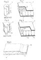
- Fig. 1 two metal layers 1, 2 are shown as cover layers made of aluminum with a plurality of aligned, aligned tubes 3, which together form a composite body. From the partial cross section in Fig. 2 it can be seen that the tube ends are open, but are thickened relative to the central wall area.
- the free buckling length Kl is given as a measure of the rigidity. The greater the kink length Kl, the more the tube walls tend to buckle under load in the direction of the tube axis.
- FIG. 3 shows, analogously to FIG. 1, a partial cross section of the composite body according to the invention with metal layers. 4, 5 as cover layers and a variety of tubes.
- the tubes 6 are now closed at their ends 8. This can also be seen from the illustration in FIG. 4, in which the kink length is denoted by Kl and the console-like thickening by 7.
- the tube body 9 is located between two aluminum cover layers 10; 11.
- the cover layer 10 was preformed in the edge region before being brought together with the core layer.
- FIG. 6 shows the preformed cover layer 12 "and the tube plate 13 before the connection
- FIG. 7 shows the composite body with cover layer 14 and filler (tube plate) 15.
- the filler has to take on additional pressure and tensile stress. This takes place in the production of the composite body according to the invention in that during hot pressing, due to the shape of the cover layer 16, the tube plate is melted together more in concave regions of the preformed cover layer (FIG. 8).
- the spatial density of the tube body in these areas allows a higher stress absorption. It can be improved up to 100% by selecting the tube plate thickness. The material displaced during compression is taken up in the cavities of the tubes. The spatial density of 100% of the plastic core is also achieved if the space of the filler is practically brought to zero with two cover layers, e.g. when a seal 19 is reached (FIG. 9).
- the lower cover layer is numbered 17 and the compressed area is 18.
Landscapes
- Engineering & Computer Science (AREA)
- Mechanical Engineering (AREA)
- Laminated Bodies (AREA)
Abstract
Description
- Die Erfindung betrifft ein Verfahren zur Herstellung eines insbesondere thermoplastischen Verbundkörpers/auf der Basis Polypropylen oder Polycarbonat, bestehend im wesentlichen aus einer Aneinanderreihung von gleichgerichteten, dünnwandigen Röhrchen, die durch thermisches Schneiden quer zur Röhrchenachse zu Röhrchenkörpern ausgeformt werden.
- Nach DE-OS 27 49 764 (Solvay) ist ein Verbundmaterial in Form einer Verbundplatte bekannt, welche eine durch Heißpressen mit einer Polyolefinfolie verbundene Metallfolie umfasst. Die Polyolefinfolie besteht dabei aus 10 bis 90 Gew.-% zelluloseartiger Fasern, die auch in Form von fibrilierten Strukturen vorliegen können.
- Nach DE-OS 30 12 372 (Sandwich-Profil GmbH) ist ein Kollektorelement bekannt, das aus Kapillarenstücken aus Glas oder Kunststoff gebildet wird. Die Kunststoffkapillare können beispielsweise mit einem Spinnkopf hergestellt werden, wie er in DE-PS 10 47 984 beschrieben ist.
- Für viele Anwendungsbereiche ist es wichtig, daß bei vorgegebener Dicke des Verbundkörpers hohe Festigkeitswerte bei möglichst geringem spezifischem Gewicht erreicht werden. Diesen Anforderungen genügen die bisher bekannten Verbundmaterislien nicht in ausreichendem Maße.
- Sie gestatten ferner nur die Verbindung von ebenen Deckschichten mit ebenen Kernmaterialien zu Verbundwerkstoffen.
- Aufgabe der vorliegenden Erfindung ist es daher, ein Verfahren zur Herstellung eines Verbundkörpers aus thermoplastischem Material anzubieten, der hohe Festigkeitswerte bei niedriger Dichte ausweist.
- Die Aufgabe wird bei einem Verfahren der eingangs genannten Art dadurch gelöst, daß man eine Aneinanderreihung von gleichgerichteten Röhrchen in Plattenform bringt, diese mit mindestens einer Metallage unter Druck und Temperatur verbindet, wobei die Röhrchenenden im plastischen Zustand heruntergeschmolzen werden, dabei in Abhängigkeit von Röhrchendurchmesser, Wandstärke und Abschmelzgrad zunehmend verdickt werden und eine Konsole ausgebildet wird, die gleichzeitig mit der Metallage schmelztechnisch verbunden wird.
- Aufgrund ihrer materialspezifischen Eigenschaften ist es bei dieser Verbundkonstruktion vorteilhaft, daß die Metalllagen aus Aluminium und das thermoplastische Material aus Polypropylen oder Polycarbonat bestehen.
- Für den Fall besonders hoher Beanspruchungen sind die Wandungen der Röhrchen zum Röhrchenende hin verdickt und am Röhrchenende eine Konsole und ein materialeigener Verschluß aus dem thermoplastischen Material ausgebildet. Durch zahlreiche Versuche hat sich herausgestellt, daß Röhrchenkörper mit dieser Querschnittsform höhere Druckbelastungen aufnehmen können als unverformte glatte Röhrchen gleicher Bauhöhe und gleicher Dichte.
- Das Verfahren zur Herstellung des erfindungsgemäßen Verbundkörpers verläuft in folgenden Schritten:
- 1. Eine Aneinanderreihung von gleichgerichteten Röhrchen in Plattenform wird mit mindestens einer waagerecht zur Röhrchenachse angeordneten Metallage unter Druck und Temperatur verbunden (Fig. 1).
- 2. Die Röhrchenenden werden im plastischen Zustand heruntergeschmolzen, so daß sie sich dabei in Abhängigkeit von Röhrchendurchmesser, Röhrchenwandstärke und Abschmelzgrad zunehmend verdicken (Fig. 2).
- 3. An den Röhrchenenden bilden sich Konsolen oder ein materialeigener Verschluß, der sich mit der Metalllage schmelztechnisch verbindet (Fig. 4).
- 4. Die Röhrchenenden werden im plastischen Zustand soweit heruntergeschmolzen, bis sie vollflächig an der Kontur der vorgeformten Deckschicht anliegen (Fig. 7).
- Die bei der Herstellung anfallenden Temperaturen liegen kurz über dem Erweichungspunkt des jeweiligen thermoplastischen Materials, vorzugsweise z.B.'Polyäthylen, Polycarbonat oder Polypropylen.
- Vorteilhafterweise ist die Ausgangswanddicke der Röhrchen 0,1 bis 0,5 mm und der Außendurchmesser < 3 mm.
- Durch Änderung der Geometrie des statisch belasteten Röhrchenkörpers sowie durch Verdickung der Röhrchenwandung zum Röhrechenende hin wird erreicht, daß die kritische Knicklänge der Wandung reduziert wird und somit die Belastbarkeit des Verbundkörpers in Faserrichtung in Abhängigkeit mit der Verkleinerung der Knicklänge wächst (Fig. 1 - 4 u. siehe Knicklänge Kl).
- Durch die zusätzliche sogenannte Konsolenbildung (Fig. 1 und 2) oder materialeigene Verschlußbildung (Fig. 3 und 4) an den Rohrenden werden die Kontaktflächen zwischen Röhrchenenden und Deckschichten vergrößert, wodurch die Haftung zwischen beiden Materialien wesentlich verbessert wird.
- Obige Gestaltung des Kunststoffkerns läuft im Fertigungsprozeß des Verbundes zeitgleich mit der Schmelzverbindung der Metalllagen ab. Bei diesem Fertigungsverfahren haben sich besonders Metallagen aus Aluminium bewährt, die entsprechend der bekannten Art im coil-coating-Verfahren speziell für diese Anwendung vorbehandelt werden, um eine optimale Haftung zwischen Metallage und Kernwerkstoff zu gewährleisten.
- Hierzu sind vorzugsweise die Metallagen zum Kernwerkstoff hin geprimert und mit einem Haftvermittler im Dickenbereich von 0,010 bis 0,120 mm versehen.
- Der festigkeitstragende Kern ist aus einer Aneinanderreihung von gleichgerichteten, senkrecht zur Deckschicht angeordneten Röhrchen gebildet, wobei ganze Röhrchenplatten durch thermisches Schneiden von einzelnen Röhrehenbündeln hergestellt werden. Die einzelnen Röhrchen lassen sich vorzugsweise spinntechnisch praktisch endlos erzeugen (s. DE-PS 10 47 984).
- Insgesamt ergibt sich bei der erfindungsgemäßen Konstruktion ein erheblich verringertes spezifisches Gewicht bei gleichzeitig ausreichender Gesamtfestigkeit. Im Vergleich zu marktgängigen Verbundplatten mit Metalldeckschichten und einem thermoplastischen Vollkern nach P 19 32 890.6 beträgt die Gewichtsreduzierung des Kerns je nach Ausführungsart 50 bis 85 % bei gleicher Plattendicke.
- Die erfindungsgemäße Herstellung des Verbundkörpers geschieht unter kurzer Wärmebeaufschlagung bis zum Erweichungspunkt des jeweiligen Thermoplasten in den oberen und unteren Röhrchenendbereichen.
- Eine bevorzugte Ausführungsform der Erfindung betrifft ein Verfahren zur Herstellung von Verbundelementen, bestehend aus vorverformten Deckschichten aus Metallen oder Kunststoffen mit Wanddieken < 2 mm und einem thermoplastischen Körper, der im wesentlichen aus einer Aneinanderreihung von gleichgerichteten, senkrecht zur Deckschicht angeordneten Röhrchenkörpern besteht. Die Deckschichten und die Röhrchenkörper werden thermisch beaufschlagt und unter Druck schmelztechnisch miteinander verbunden.
- Die Außendurchmesser der Röhrchenkörper liegen vorzugsweise zwischen 0,5 bis 6 mm. Diese Röhrchen werden beispielsweise entsprechend DE-PS 10 47 984 hergestellt.
- Es ist möglich, die Deckschichten zu verformen oder dekorativ zu prägen und dann mit dem Röhrchenkörper zu verbinden. Diese neuen Strukturen bilden sich bei dem späteren Kaschiervorgang nicht zurück, da sich die Röhrchen durch die thermische Beaufschlagung während des Kaschiervorganges ohne Haftungsverluste der jeweiligen Form oder Struktur der Deckschichten anpassen.
- Ferner wird erfindungsgemäß angestrebt, beim Verbindungs- oder Kaschiervorgang durch weiteres thermisches Zusammenpressen der Röhrchen über das Maß der vorherigen Verdichtung hinaus im Randbereich der Platte zusätzliche Verformungen und Festigkeitssteigerungen des Verbundes zu erreichen (Fig. 5). Das beim Zusammenpressen verdrängte Material wird in den Hohlräumen der Röhrchen aufgenommen. Trotz der hohen Verdichtung des Röhrchenkörpers liegt seine Dichte auch in diesen Bereichen noch wesentlich unter der eines Vollkunststoffkerns.
- Im folgenden wird die Erfindung anhand von drei Ausführungsbeispielen näher erläutert: Es zeigen:
- Fig. 1 - Perspektivischer Querschnitt durch einen erfindungsgemäßen Verbundkörper bei ca. 30 % Kernverdichtung
- Fig. 2 - Teilquerschnitt durch ein Röhrchen gemäß Schnittlinie A, B aus Fig. 1 mit Konsolenbildung
- Fig. 3 - Perspektivischer Querschnitt durch einen erfindungsgemäßen Verbundkörper mit ca. 50 % Kernverdichtung
- Fig. 4 - Teilquerschnitt durch ein geschlossenes Röhrchen entlang Schnittlinie C, D aus Fig. 3 mit Konsolenbildung und materialeigenem Verschluß
- Fig. 5 - Querschnitt durch einen erfindungsgemäßen Verbundkörper mit Verformungen im Randbereich
- Fig. 6 - vorgeformte Deckschicht und Röhrchenplatte vor dem Verbinden
- Fig. 7 - Verbundkörper mit Deckschicht und Füllstoff (Röhrchenplatte)
- Fig. 8 - Verbundkörper mit oberer und unterer Deckschicht und verdichtetem Bereich
- Fig. 9 - Verbundkörper mit versiegeltem Bereich
- In Fig. 1 sind zwei Metallagen 1, 2 als Deckschichten aus Aluminium mit einer Vielzahl von aneinandergereihten, gleichgerichteten Röhrchen 3 dargestellt, die zusammen einen Verbundkörper bilden. Aus dem Teilquerschnitt in Fig. 2 ist zu erkennen, daß die Röhrchenenden zwar offen, aber gegenüber dem mittleren Wandbereich verdickt sind. Die freie Knicklänge Kl ist als Maß für die Steifigkeit angegeben. Je größer die Knicklänge Kl, desto eher neigen die Röhrchenwandungen zum Ausknicken bei Belastung in Richtung der Röhrchenachse.
- Fig. 3 zeigt analog zu Fig. 1 einen Teilquerschnitt des erfindungsgemäßen Verbundkörpers mit Metalllagen. 4, 5 als Deckschichten und einer Vielzahl von Röhrchen. Im Gegensatz zu den in Fig. 1, 2 dargestellten Röhrchen 3 sind die Röhrchen 6 nunmehr an ihren Enden 8 verschlossen. Dies geht auch aus der Darstellung in Fig. 4 hervor, bei der die Knicklänge mit Kl und die konsolenartige Verdikkung mit 7 bezeichnet ist.
- Anhand von Fig. 5 soll die Möglichkeit einer noch weiteren zusätzlichen Verdichtung des Kernmaterials in bestimmten Oberflächenbereichen bei der Verbundfertigung dargestellt werden.
- Der Röhrchenkörper 9 befindet sich zwischen zwei Aluminiumdeckschichten 10; 11. Die Deckschicht 10 wurde vor dem Zusammenbringen mit der Kernschicht im Randbereich vorgeformt.
- Fig. 6 zeigt die vorgeformte Deckschicht 12" und die Röhrchenplatte 13 vor dem Verbinden, während Fig. 7 den Verbundkörper mit Deckschicht 14 und Füllstoff (Röhrchenplatte) 15 darstellt.
- Um auch die Deckschichten abmagern zu können - aus technischen oder preislichen Gründen - muß der Füllstoff zusätzlich Druck- und Zugaufnahmebeanspruchungen übernehmen. Dies erfolgt bei der Herstellung des erfindungsgemäßen Verbundkörpers dadurch, daß bei der Heißpressung,bedingt durch die Formgebung der Deckschicht 16,die Röhrchenplatte in konkaven Bereichen der vorgeformten Deckschicht stärker zusammengeschmolzen wird (Fig. 8).
- Die Raumdichte des Röhrchenkörpers in diesen Bereichen erlaubt eine höhere Beanspruchungsaufnahme. Sie kann durch die Auswahl der Röhrchenplattendicke bis zu 100 % verbessert werden. Das beim Zusammenpressen verdrängte Material wird in den Höhlräumen der Röhrchen aufgenommen. Die Raumdichte von 100 % des Kunststoffkerns wird auch erreicht, wenn bei 2 Deckschichten der Raum des Füllstoffes praktisch auf Null zusammengefahren wird, z.B. bei Erreichung einer Siegelung 19 (Fig. 9).
- In Fig. 8 sind die untere Deckschicht mit 17 und der verdichtete Bereich mit 18 beziffert.
Claims (5)
Priority Applications (1)
| Application Number | Priority Date | Filing Date | Title |
|---|---|---|---|
| AT84108839T ATE43996T1 (de) | 1983-08-01 | 1984-07-26 | Verfahren zur herstellung eines thermoplastischen verbundkoerpers. |
Applications Claiming Priority (2)
| Application Number | Priority Date | Filing Date | Title |
|---|---|---|---|
| DE19833327694 DE3327694A1 (de) | 1983-08-01 | 1983-08-01 | Thermoplastischer koerper auf der basis polypropylen oder polycarbonat |
| DE3327694 | 1983-08-01 |
Publications (3)
| Publication Number | Publication Date |
|---|---|
| EP0135708A2 true EP0135708A2 (de) | 1985-04-03 |
| EP0135708A3 EP0135708A3 (en) | 1987-01-28 |
| EP0135708B1 EP0135708B1 (de) | 1989-06-14 |
Family
ID=6205449
Family Applications (1)
| Application Number | Title | Priority Date | Filing Date |
|---|---|---|---|
| EP84108839A Expired EP0135708B1 (de) | 1983-08-01 | 1984-07-26 | Verfahren zur Herstellung eines thermoplastischen Verbundkörpers |
Country Status (3)
| Country | Link |
|---|---|
| EP (1) | EP0135708B1 (de) |
| AT (1) | ATE43996T1 (de) |
| DE (2) | DE3327694A1 (de) |
Cited By (6)
| Publication number | Priority date | Publication date | Assignee | Title |
|---|---|---|---|---|
| WO1989000497A1 (en) * | 1987-07-20 | 1989-01-26 | Courtaulds Plc | Composite article of varying thickness and its production |
| WO1989003299A1 (fr) * | 1987-10-08 | 1989-04-20 | Hellmuth Costard | Element modulaire leger a structure en sandwich |
| FR2712839A1 (fr) * | 1993-11-26 | 1995-06-02 | Lorraine Laminage | Procédé et dispositif de fabrication en continu de tôles métalliques dites "tôles sandwich", et tôles ainsi obtenues. |
| WO1998004398A1 (fr) * | 1996-07-30 | 1998-02-05 | Peguform France | Formation d'un insert dans un panneau en materiau composite du type sandwich a ame alveolaire |
| WO2000064659A1 (de) * | 1999-04-26 | 2000-11-02 | Kr-Porsiplast Verpackungssysteme Gmbh | Verfahren und vorrichtung zum verformen von hohlkörperplatten aus thermoplastischem material |
| US6613269B1 (en) | 1999-04-26 | 2003-09-02 | Kr-Porsiplast Verpackungssysteme Gmbh | Method and device for shaping hollow bodies made of thermoplastic material |
Families Citing this family (2)
| Publication number | Priority date | Publication date | Assignee | Title |
|---|---|---|---|---|
| DE4314861A1 (de) * | 1993-05-05 | 1994-11-10 | Tubus Bauer Gmbh | Verfahren zur Herstellung eines Wabenkörpers sowie Wabenkörper |
| DE29602179U1 (de) * | 1996-02-08 | 1996-04-25 | HDW-Isoliertechnik GmbH, 24149 Kiel | Dämm- und/oder Lichtleitelement |
Family Cites Families (4)
| Publication number | Priority date | Publication date | Assignee | Title |
|---|---|---|---|---|
| FR1254208A (fr) * | 1959-04-14 | 1961-02-17 | Platenius Vertriebs G M B H | Procédé de fabrication de corps composites, notamment de plaques, et corps fabriqués suivant ce procédé |
| US3134705A (en) * | 1962-10-15 | 1964-05-26 | Dow Chemical Co | Honeycomb fabrication |
| DE1959976A1 (de) * | 1969-11-29 | 1971-06-16 | Hamburger Flugzeugbau Gmbh | Leichtbauteil aus Kunststoffroehrchen |
| AT298011B (de) * | 1969-12-04 | 1972-04-25 | Adolf Heinz Ing Malinsky | Bauelement und Verfahren zu dessen Herstellung |
-
1983
- 1983-08-01 DE DE19833327694 patent/DE3327694A1/de not_active Withdrawn
-
1984
- 1984-07-26 DE DE8484108839T patent/DE3478674D1/de not_active Expired
- 1984-07-26 AT AT84108839T patent/ATE43996T1/de not_active IP Right Cessation
- 1984-07-26 EP EP84108839A patent/EP0135708B1/de not_active Expired
Cited By (10)
| Publication number | Priority date | Publication date | Assignee | Title |
|---|---|---|---|---|
| WO1989000497A1 (en) * | 1987-07-20 | 1989-01-26 | Courtaulds Plc | Composite article of varying thickness and its production |
| WO1989003299A1 (fr) * | 1987-10-08 | 1989-04-20 | Hellmuth Costard | Element modulaire leger a structure en sandwich |
| AU615690B2 (en) * | 1987-10-08 | 1991-10-10 | Hellmuth Costard | Light-weight constructional element of sandwich structure |
| GR1000879B (el) * | 1987-10-08 | 1993-03-16 | Hellmuth Costard | Ελαφρό κατασκευαστικό στοιχείο σε μορφή κατασκευής σάντουϊτς. |
| FR2712839A1 (fr) * | 1993-11-26 | 1995-06-02 | Lorraine Laminage | Procédé et dispositif de fabrication en continu de tôles métalliques dites "tôles sandwich", et tôles ainsi obtenues. |
| WO1998004398A1 (fr) * | 1996-07-30 | 1998-02-05 | Peguform France | Formation d'un insert dans un panneau en materiau composite du type sandwich a ame alveolaire |
| FR2751914A1 (fr) * | 1996-07-30 | 1998-02-06 | Manducher Sa | Formation d'un insert dans un panneau en materiau composite du type sandwich a ame alveolaire |
| WO2000064659A1 (de) * | 1999-04-26 | 2000-11-02 | Kr-Porsiplast Verpackungssysteme Gmbh | Verfahren und vorrichtung zum verformen von hohlkörperplatten aus thermoplastischem material |
| US6613269B1 (en) | 1999-04-26 | 2003-09-02 | Kr-Porsiplast Verpackungssysteme Gmbh | Method and device for shaping hollow bodies made of thermoplastic material |
| US6923928B1 (en) | 1999-04-26 | 2005-08-02 | Kr-Porsiplast Verpackungssysteme Gmbh | Method and device for shaping thermoplastic hollow boards |
Also Published As
| Publication number | Publication date |
|---|---|
| EP0135708B1 (de) | 1989-06-14 |
| DE3327694A1 (de) | 1985-06-27 |
| EP0135708A3 (en) | 1987-01-28 |
| ATE43996T1 (de) | 1989-06-15 |
| DE3478674D1 (en) | 1989-07-20 |
Similar Documents
| Publication | Publication Date | Title |
|---|---|---|
| DE68927806T2 (de) | Poröse Struktur | |
| EP0446778B1 (de) | Formstabilisierter Rolladenstab und Verfahren zu seiner Herstellung | |
| DE2353610A1 (de) | Endkappe mit mindestens einer umfangsnut, insbesondere zur abdeckung eines rohrfoermigen filterlements, verfahren zur herstellung einer solchen endkappe und verbindung der endkappe mit dem filterelement | |
| DE69705907T2 (de) | Herstellungsverfahren eines faserverstärkten metallischen Teils | |
| DE3405456C2 (de) | Verbindung zweier Bauteile, insbesondere zweier Kunststoff-Halbschalen für die Sauganlage einer Brennkraftmaschine | |
| EP0135708B1 (de) | Verfahren zur Herstellung eines thermoplastischen Verbundkörpers | |
| DE19810706C2 (de) | Doppellagenblech aus zwei Deckblechen und einer Zwischenlage | |
| EP1815969B1 (de) | Flugzeugbauteil sowie Verfahren zur Herstellung eines Flugzeugbauteiles | |
| DE102004032362A1 (de) | Verfahren zur Herstellung eines Verbund-Bauteils sowie Verbund-Bauteil | |
| WO1991015350A2 (de) | Verfahren zur herstellung einer tube mit einem mehrschichtigen tubenkopf und tube aus einem mindestens eine kunststoffschicht aufweisenden rohrkörper und einem mehrschichtigen tubenkopf | |
| DE102019216528A1 (de) | Integrierte struktur aus verschiedenen arten von materialien und verfahren zur integration verschiedener arten von materialien | |
| EP0394639B1 (de) | Greiferstange aus faserverstärkten Kunststoffbändern | |
| DE3851384T2 (de) | Verfahren und Vorrichtung zum Herstellen eines Zellenverbundes aus Rohren, Anwendungen dieses Verbundes und damit aufgebaute Platte. | |
| WO2011082933A1 (de) | Kompaktfilter, verfahren zur herstellung eines kompaktfilters und filtermedium | |
| DE1596398A1 (de) | Verfahren zum Verbinden multipler opti?ner Fasern zur Herstellung von Bildschirmen von Kathodenstrahlroehren | |
| EP0685981A2 (de) | Lautsprecher | |
| DE102016223030A1 (de) | LWRT-Werkstoff mit in Pressform nicht haftender Deckschicht und Kfz-Bauteil aus solchem LWRT-Werkstoff | |
| WO1990006797A1 (de) | Fertigformteil für filterplatten | |
| DE102014208835A1 (de) | Verfahren zur Herstellung eines Kunststoffbauteils | |
| DE8322136U1 (de) | Thermoplastischer Körper auf der Basis Polypropylen oder Polycarbonat | |
| WO2022199978A1 (de) | Karosseriebauteil, fahrzeug, halbzeug und verfahren zum herstellen eines karosseriebauteils | |
| DE19604613A1 (de) | Sandwichstruktur | |
| EP3078492B1 (de) | Tiefziehfähige folie und verfahren zur herstellung einer tiefziehfähigen folie | |
| DE102008050210B4 (de) | Verfahren zum Verformen von thermoplastischen Wabenkörpern | |
| DE3039579A1 (de) | Tiefziehfaehige stegdoppelplatte |
Legal Events
| Date | Code | Title | Description |
|---|---|---|---|
| PUAI | Public reference made under article 153(3) epc to a published international application that has entered the european phase |
Free format text: ORIGINAL CODE: 0009012 |
|
| AK | Designated contracting states |
Designated state(s): AT BE CH DE FR GB IT LI LU NL SE |
|
| PUAL | Search report despatched |
Free format text: ORIGINAL CODE: 0009013 |
|
| AK | Designated contracting states |
Kind code of ref document: A3 Designated state(s): AT BE CH DE FR GB IT LI LU NL SE |
|
| 17P | Request for examination filed |
Effective date: 19870325 |
|
| 17Q | First examination report despatched |
Effective date: 19871221 |
|
| GRAA | (expected) grant |
Free format text: ORIGINAL CODE: 0009210 |
|
| RAP1 | Party data changed (applicant data changed or rights of an application transferred) |
Owner name: VEREINIGTE ALUMINIUM-WERKE AKTIENGESELLSCHAFT |
|
| AK | Designated contracting states |
Kind code of ref document: B1 Designated state(s): AT BE CH DE FR GB IT LI LU NL SE |
|
| REF | Corresponds to: |
Ref document number: 43996 Country of ref document: AT Date of ref document: 19890615 Kind code of ref document: T |
|
| ITF | It: translation for a ep patent filed | ||
| REF | Corresponds to: |
Ref document number: 3478674 Country of ref document: DE Date of ref document: 19890720 |
|
| GBT | Gb: translation of ep patent filed (gb section 77(6)(a)/1977) | ||
| ET | Fr: translation filed | ||
| PLBE | No opposition filed within time limit |
Free format text: ORIGINAL CODE: 0009261 |
|
| STAA | Information on the status of an ep patent application or granted ep patent |
Free format text: STATUS: NO OPPOSITION FILED WITHIN TIME LIMIT |
|
| 26N | No opposition filed | ||
| ITTA | It: last paid annual fee | ||
| PGFP | Annual fee paid to national office [announced via postgrant information from national office to epo] |
Ref country code: FR Payment date: 19930715 Year of fee payment: 10 |
|
| PGFP | Annual fee paid to national office [announced via postgrant information from national office to epo] |
Ref country code: GB Payment date: 19930716 Year of fee payment: 10 |
|
| PGFP | Annual fee paid to national office [announced via postgrant information from national office to epo] |
Ref country code: LU Payment date: 19930723 Year of fee payment: 10 |
|
| PGFP | Annual fee paid to national office [announced via postgrant information from national office to epo] |
Ref country code: SE Payment date: 19930726 Year of fee payment: 10 Ref country code: AT Payment date: 19930726 Year of fee payment: 10 |
|
| PGFP | Annual fee paid to national office [announced via postgrant information from national office to epo] |
Ref country code: NL Payment date: 19930731 Year of fee payment: 10 |
|
| PGFP | Annual fee paid to national office [announced via postgrant information from national office to epo] |
Ref country code: BE Payment date: 19930804 Year of fee payment: 10 |
|
| PGFP | Annual fee paid to national office [announced via postgrant information from national office to epo] |
Ref country code: CH Payment date: 19930819 Year of fee payment: 10 |
|
| PGFP | Annual fee paid to national office [announced via postgrant information from national office to epo] |
Ref country code: DE Payment date: 19930917 Year of fee payment: 10 |
|
| EPTA | Lu: last paid annual fee | ||
| PG25 | Lapsed in a contracting state [announced via postgrant information from national office to epo] |
Ref country code: LU Free format text: LAPSE BECAUSE OF NON-PAYMENT OF DUE FEES Effective date: 19940726 Ref country code: GB Effective date: 19940726 Ref country code: AT Effective date: 19940726 |
|
| PG25 | Lapsed in a contracting state [announced via postgrant information from national office to epo] |
Ref country code: SE Effective date: 19940727 |
|
| PG25 | Lapsed in a contracting state [announced via postgrant information from national office to epo] |
Ref country code: LI Effective date: 19940731 Ref country code: CH Effective date: 19940731 Ref country code: BE Effective date: 19940731 |
|
| BERE | Be: lapsed |
Owner name: VEREINIGTE ALUMINIUM-WERKE A.G. Effective date: 19940731 |
|
| EUG | Se: european patent has lapsed |
Ref document number: 84108839.6 Effective date: 19950210 |
|
| PG25 | Lapsed in a contracting state [announced via postgrant information from national office to epo] |
Ref country code: NL Effective date: 19950201 |
|
| NLV4 | Nl: lapsed or anulled due to non-payment of the annual fee | ||
| GBPC | Gb: european patent ceased through non-payment of renewal fee |
Effective date: 19940726 |
|
| PG25 | Lapsed in a contracting state [announced via postgrant information from national office to epo] |
Ref country code: FR Effective date: 19950331 |
|
| REG | Reference to a national code |
Ref country code: CH Ref legal event code: PL |
|
| PG25 | Lapsed in a contracting state [announced via postgrant information from national office to epo] |
Ref country code: DE Effective date: 19950401 |
|
| EUG | Se: european patent has lapsed |
Ref document number: 84108839.6 |
|
| REG | Reference to a national code |
Ref country code: FR Ref legal event code: ST |