EP0135730A2 - Selbstpumpendes hydrodynamisches Gleitlager - Google Patents
Selbstpumpendes hydrodynamisches Gleitlager Download PDFInfo
- Publication number
- EP0135730A2 EP0135730A2 EP84109161A EP84109161A EP0135730A2 EP 0135730 A2 EP0135730 A2 EP 0135730A2 EP 84109161 A EP84109161 A EP 84109161A EP 84109161 A EP84109161 A EP 84109161A EP 0135730 A2 EP0135730 A2 EP 0135730A2
- Authority
- EP
- European Patent Office
- Prior art keywords
- lubricant
- pump
- gap
- self
- plain bearing
- Prior art date
- Legal status (The legal status is an assumption and is not a legal conclusion. Google has not performed a legal analysis and makes no representation as to the accuracy of the status listed.)
- Granted
Links
Images
Classifications
-
- F—MECHANICAL ENGINEERING; LIGHTING; HEATING; WEAPONS; BLASTING
- F16—ENGINEERING ELEMENTS AND UNITS; GENERAL MEASURES FOR PRODUCING AND MAINTAINING EFFECTIVE FUNCTIONING OF MACHINES OR INSTALLATIONS; THERMAL INSULATION IN GENERAL
- F16C—SHAFTS; FLEXIBLE SHAFTS; ELEMENTS OR CRANKSHAFT MECHANISMS; ROTARY BODIES OTHER THAN GEARING ELEMENTS; BEARINGS
- F16C33/00—Parts of bearings; Special methods for making bearings or parts thereof
- F16C33/02—Parts of sliding-contact bearings
- F16C33/04—Brasses; Bushes; Linings
- F16C33/06—Sliding surface mainly made of metal
- F16C33/10—Construction relative to lubrication
- F16C33/1025—Construction relative to lubrication with liquid, e.g. oil, as lubricant
- F16C33/106—Details of distribution or circulation inside the bearings, e.g. details of the bearing surfaces to affect flow or pressure of the liquid
- F16C33/1075—Wedges, e.g. ramps or lobes, for generating pressure
-
- F—MECHANICAL ENGINEERING; LIGHTING; HEATING; WEAPONS; BLASTING
- F16—ENGINEERING ELEMENTS AND UNITS; GENERAL MEASURES FOR PRODUCING AND MAINTAINING EFFECTIVE FUNCTIONING OF MACHINES OR INSTALLATIONS; THERMAL INSULATION IN GENERAL
- F16C—SHAFTS; FLEXIBLE SHAFTS; ELEMENTS OR CRANKSHAFT MECHANISMS; ROTARY BODIES OTHER THAN GEARING ELEMENTS; BEARINGS
- F16C17/00—Sliding-contact bearings for exclusively rotary movement
- F16C17/04—Sliding-contact bearings for exclusively rotary movement for axial load only
- F16C17/047—Sliding-contact bearings for exclusively rotary movement for axial load only with fixed wedges to generate hydrodynamic pressure
-
- F—MECHANICAL ENGINEERING; LIGHTING; HEATING; WEAPONS; BLASTING
- F16—ENGINEERING ELEMENTS AND UNITS; GENERAL MEASURES FOR PRODUCING AND MAINTAINING EFFECTIVE FUNCTIONING OF MACHINES OR INSTALLATIONS; THERMAL INSULATION IN GENERAL
- F16C—SHAFTS; FLEXIBLE SHAFTS; ELEMENTS OR CRANKSHAFT MECHANISMS; ROTARY BODIES OTHER THAN GEARING ELEMENTS; BEARINGS
- F16C33/00—Parts of bearings; Special methods for making bearings or parts thereof
- F16C33/02—Parts of sliding-contact bearings
- F16C33/04—Brasses; Bushes; Linings
- F16C33/06—Sliding surface mainly made of metal
- F16C33/10—Construction relative to lubrication
- F16C33/1025—Construction relative to lubrication with liquid, e.g. oil, as lubricant
- F16C33/106—Details of distribution or circulation inside the bearings, e.g. details of the bearing surfaces to affect flow or pressure of the liquid
- F16C33/1085—Channels or passages to recirculate the liquid in the bearing
-
- F—MECHANICAL ENGINEERING; LIGHTING; HEATING; WEAPONS; BLASTING
- F16—ENGINEERING ELEMENTS AND UNITS; GENERAL MEASURES FOR PRODUCING AND MAINTAINING EFFECTIVE FUNCTIONING OF MACHINES OR INSTALLATIONS; THERMAL INSULATION IN GENERAL
- F16C—SHAFTS; FLEXIBLE SHAFTS; ELEMENTS OR CRANKSHAFT MECHANISMS; ROTARY BODIES OTHER THAN GEARING ELEMENTS; BEARINGS
- F16C37/00—Cooling of bearings
- F16C37/002—Cooling of bearings of fluid bearings
-
- F—MECHANICAL ENGINEERING; LIGHTING; HEATING; WEAPONS; BLASTING
- F16—ENGINEERING ELEMENTS AND UNITS; GENERAL MEASURES FOR PRODUCING AND MAINTAINING EFFECTIVE FUNCTIONING OF MACHINES OR INSTALLATIONS; THERMAL INSULATION IN GENERAL
- F16C—SHAFTS; FLEXIBLE SHAFTS; ELEMENTS OR CRANKSHAFT MECHANISMS; ROTARY BODIES OTHER THAN GEARING ELEMENTS; BEARINGS
- F16C2380/00—Electrical apparatus
- F16C2380/26—Dynamo-electric machines or combinations therewith, e.g. electro-motors and generators
Definitions
- the present invention relates to a self-pumping hydrodynamic plain bearing according to the preamble of claim 1.
- the external placement of the cooler means that the lubricant is pumped from the plain bearing environment to the cooler. For reasons of reliability, externally driven pumps are not always accepted for this purpose.
- the autonomous, safe operation of the system can only be guaranteed if the lubricant can be conveyed and maintained by the plain bearing itself.
- radial or quasi-radial bores are provided in the rotating race.
- This solution is characterized by the fact that the bores in the race do not affect the sliding surfaces of the race / support bearing segment and the race / guide bearing segment.
- the lubricant Due to the centrifugal force, the lubricant is conveyed outwards along the bore, where it is collected centrally and fed to the external cooling system.
- the conveyance caused by centrifugal force causes a suction effect at the entry into the holes.
- the invention seeks to remedy this.
- the invention as characterized in the claims, is based on the object of allowing the lubricant to be replaced at a point in the system in a self-pumping hydrodynamic plain bearing of the type mentioned which is already below the liquid level without special measures.
- the lubricant is removed from the moving tread in the stationary sliding surface Pump gap pulled, which has a correspondingly strong narrowing in the direction of movement by a gradation. Part of the lubricant flow, which enters the large gap, is discharged through an attached lubricant drainage channel before the restriction. This branched-off lubricant flow represents the delivery volume of the pump gap, the rest continues to flow through the narrow lubrication gap.
- the pump pressure which is built up hydrodynamically in the pump gap, can be varied over a wide range.
- such a pump does not lose any of the delivery capacity, but rather - in accordance with the higher pressure drop in the cooler and in the pipelines - the pump capacity increases with more viscous lubricant.
- Another advantage of the invention is that the conveyance of the lubricant and its outflow takes place outside the moving component, which is why, especially in the case of rotating races, no seals with additional additional losses are required.
- the pump gaps are integrated into the radial or axial bearing segments.
- the pump gaps of a bearing segment or stationary component are arranged in mirror image to one another, whereby the function of the pump is guaranteed for both directions of rotation of the machine.
- the lubricant channel which is attached before the constriction of the pump gap is designed to be inclined in the outflow direction, as a result of which the outflow is facilitated.
- the moving component is designed as an intermediate element for transmitting motion of a shaft rotating outside the lubricant bath and passes through at least one pump gap in the lubricant bath, as a result of which lubricant delivery can be maintained.
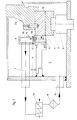
- Fig. 1 shows a vertical self-pumping hydrodynamic plain bearing l.
- the moving component 2 which is a rotating race here, is supported in the circumferential direction by a plurality of fixed support bearing segments 3, which in turn are anchored on a support 8.
- the flange 2a is connected to the race 2 by means of several pins 2b, this being part of the machine rotor, not shown. Of course, other connection techniques can be used between the race 2 and flange 2a.
- the race 2 is held by several stationary components 4, which are guide bearing segments here.
- the lubricant 19 conveyed by the individual guide bearing segments 4 reaches the collecting duct 6 from the inside of the segment via connecting pieces 5.
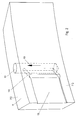
- FIG. 2 shows a guide bearing segment 4 with the incorporated pump gap 13.
- the lubricant is pumped from the pump gap 13 through a lubricant drain channel 14 into an outflow bore 15.
- This channel 14 is designed to be inclined in the outflow direction of the lubricant 19 in order to utilize the fluid pulse.
- the delivered lubricant 19 is guided away from the guide bearing segment 4 from the outflow bore 15.
- the drain transverse to the direction of movement is limited by laterally attached edge strips 20, the distance to the rotating race 2 is reduced to the lubrication gap height 18 (see FIG. 3).
- the pump gap 13 the design of which is free, can also be attached to the moving sliding surface in a separate component, or, as can be seen in FIG. 2, it can be incorporated directly into an already existing guide bearing segment 4 at the beginning of the sliding surface.
- the course of the gradation 16 of the pump gap height 13a in the direction of movement is also free. It can be used for any bearing geometry (axial bearing, radial bearing).
- the pump gap 13, together with the lubricant outflow channel 14 and outflow bore 15, can be provided on both sides of the running surface of the guide bearing segment 4.
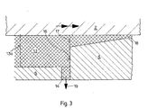
- Fig. 3 shows how the conveying effect is generated on the moving sliding surface.
- the lubricant is drawn from the moving tread of the race 2 into a pump gap 13, which has a large narrowing 17 of the pump gap height 13a in the direction of movement by means of a gradation 16.
- a part of the lubricant flow that enters the gap 13 is discharged through an attached lubricant drain channel 14 before the constriction 17.
- This branched-off lubricant flow 19 represents the delivery rate of the pump gap 13, the rest flows through the lubrication gap 18 between the race 2 and the guide bearing segment 4.
- the pump pressure corresponds to the pressure built up hydrodynamically in the gap 13 and can be controlled by the length and height of the pump gap 13.
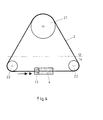
- FIG. 4 shows a possible application of self-pumping lubricant delivery with the aid of the pump gap 13 described above.
- the moving component 2 here is a strap. Of course, other drive transmission aids are also possible.
- the belt 2 is driven by the shaft 21 and guided by rollers 22 which are immersed in a lubricant bath la.
- the stationary component 4 with the incorporated pump gaps 13 is also immersed there.
- the belt 2 passes through the pump gaps 13 immersed in the lubricant, thereby producing the desired self-pumping lubricant delivery which can be used to lubricate the bearings of the rotating shaft 21 and possibly other machine parts .
Landscapes
- Engineering & Computer Science (AREA)
- General Engineering & Computer Science (AREA)
- Mechanical Engineering (AREA)
- Chemical & Material Sciences (AREA)
- Oil, Petroleum & Natural Gas (AREA)
- Physics & Mathematics (AREA)
- Fluid Mechanics (AREA)
- Sliding-Contact Bearings (AREA)
- Lubricants (AREA)
- Pharmaceuticals Containing Other Organic And Inorganic Compounds (AREA)
Abstract
Description
- Die vorliegende Erfindung betrifft ein selbstpumpendes hydrodynamisches Gleitlager gemäss Oberbegriff des Patentanspruchs 1.
- Bei hydrodynamischen Gleitlagern muss das aus den Schmierfilmen austretende Schmiermittel gekühlt werden.
- Um eine leichte Zugänglichkeit für Reinigung, Reparatur etc. zu den Kühlern zu gewährleisten, werden diese vorteilhaft nicht direkt im Gehäuse des Gleitlagers untergebracht. Die aussenliegende Plazierung der Kühler bedingt jedoch, dass das Schmiermittel von der Gleitlager-Umgebung zu den Kühlern gepumpt wird. Fremdangetriebene Pumpen werden für diesen Zweck aus Zuverlässigkeitsgründen nicht immer akzeptiert.
- Erst wenn die Schmiermittelförderung durch das Gleitlager selbst erzeugt und aufrechterhalten werden kann, ist der autarke, sichere Betrieb des Systems gewährleistet.
- Bekannt ist, die Eigenförderung des Schmiermittels durch Ausnützung der Zentrifugalkraft des im Schmiermittelbad rotierenden Laufrings zu erzeugen.
- Zu diesem Zweck werden im rotierenden Laufring radiale oder quasi-radiale Bohrungen vorgesehen. Diese Lösung zeichnet sich dadurch aus, dass die Bohrungen im Laufring die Gleitflächen Laufring/Traglagersegment und Laufring/ Führungslagersegment nicht tangieren.
- Durch die Zentrifugalkraft bedingt, wird das Schmiermittel entlang der Bohrung nach aussen gefördert, wo es zentral gesammelt und der Aussenkühlung zugeleitet wird. Die zentrifugalkraftbedingte Förderung bewirkt am Eintritt in die Bohrungen eine Saugwirkung.
- Ein grosser Nachteil dieser Lösung besteht aber darin, dass die Saugwirkung während des Betriebes labil bleibt, und deshalb bietet diese Förderungsart keine angemessene Gewährleistung in der Aufrechterhaltung des Förderbetriebes. Diese Ansaugung des Schmiermittels ist oftmals problematisch, da sie im Bereich des inneren Lagerdurchmessers erfolgt, dort also, wo der Flüssigkeitsspiegel' durch die Rotation absinkt und oft Schaum entsteht, der sodann die fördernde Ansaugung zusammenbrechen lässt.
- Hier will die Erfindung Abhilfe schaffen. Der Erfindung, wie sie in den Ansprüchen gekennzeichnet ist, liegt die Aufgabe zugrunde, bei einem selbstpumpenden hydrodynamischen Gleitlager der eingangs genannten Art die Fassung des Schmiermittels an einer Stelle im System erfolgen zu lassen, die ohne besondere Massnahmen bereits unter dem Flüssigkeitsspiegel liegt.
- Das Schmiermittel wird dabei von der bewegten Lauffläche in den in der stillstehenden Gleitfläche ausgenommenen Pumpspalt gezogen, der in Bewegungsrichtung eine entsprechend starke Verengung durch eine Abstufung aufweist. Ein Teil des Schmiermittelstromes, der in den grossen Spalt eintritt, wird vor der Verengung durch einen angebrachten Schmiainittelabflusskanal abgeführt. Dieser abgezweigte Schmiermittelstrom stellt die Fördermenge des Pumpspaltes dar, der Rest strömt durch den engen Schmierspalt weiter.
- Durch die Geometrie des Pumpspaltes kann der Pumpdruck, welcher im Pumpspalt hydrodynamisch aufgebaut wird, über eine grosse Bandweite variiert werden.
- Des weiteren weist eine solche Pumpe bei höherer Viskosität des Schmiermittels keine Einbusse der Förderleistung auf, sondern - entsprechend dem höheren Druckabfall im Kühler und in den Rohrleitungen - bei zäherem Schmiermittel steigt die Pumpkapazität an.
- Ein weiterer Vorteil der Erfindung besteht darin, dass die Förderung des Schmiermittels und dessen Ablauf sich ausserhalb des bewegten Bauteils abspielt, weshalb insbesondere bei rotierenden Laufringen keine Dichtungen mit Inkaufnahme zusätzlicher Reibungsverluste erforderlich sind.
- Bei einer bevorzugten Ausführung der Erfindung werden die Pumpspalte in die Radial- oder Axiallagersegmente integriert.
- Bei einer weiteren bevorzugten Ausführung der Erfindung werden die Pumpspalte eines Lagersegmentes oder stillstehenden Bauteils spiegelbildlich zueinander angeordnet, wodurch die Funktion der Pumpe für beide Drehrichtungen der Maschine gewährleistet ist.
- Bei einer weiteren bevorzugten Ausführung der Erfindung wird der vor der Verengung des Pumpspaltes angebrachte Schmiermittelkanal in Abflussrichtung geneigt ausgebildet, wodurch der Abfluss erleichtert wird.
- Bei einer weiteren bevorzugten Ausführung der Erfindung ist der bewegte Bauteil als Zwischenelement zur Bewegungsübertragung einer ausserhalb des Schmiermittelbades rotierenden Welle ausgebildet und durchläuft im Schmiermittelbad mindestens einen Pumpspalt, wodurch eine Schmiermittelförderung aufrechterhalten werden kann.
- In der Zeichnung sind Ausführungsbeispiele der Erfindung schematisch dargestellt.
- Es zeigt:
- Fig. 1 ein komplettes selbstpumpendes hydrodynamisches Gleitlager, wobei es sich hier um eine vertikale Ausführung eines kombinierten Trag- und Führungslagers eines Wasserkraftgenerators handelt;
- Fig. 2 ein Führungslagersegment mit eingearbeitetem Pumpspalt;
- Fig. 3 die geometrische Ausführung eines Pumpspaltes und
- Fig. 4 eine Anwendungsmöglichkeit des Pumpspaltes für eine ausserhalb des Schmiermittelbades rotierende Welle.
- Alle für das unmittelbare Verständnis der Erfindung nicht erforderlichen Elemente sind fortgelassen. Die Strömungsrichtung des Schmiermittels ist mit einem einfachen Pfeil, die Bewegungsrichtung der Laufteile hingegen mit einem Doppelpfeil bezeichnet. In den verschiedenen Figuren sind jeweils gleiche Elemente mit gleichen Bezugszeichen versehen.
- Fig. 1 zeigt ein vertikales selbstpumpendes hydrodynamisches Gleitlager l. Der bewegte Bauteil 2, der hier ein rotierender Laufring ist, wird in Umfangsrichtung von mehreren feststehenden Traglagersegmenten 3 getragen, welche ihrerseits auf einem Support 8 verankert sind. Mit dem Laufring 2 ist mittels mehrerer Stifte 2b der Flansch 2a verbunden, wobei dieser Bestandteil des nicht dargestellten Maschinenrotors ist. Selbstverständlich können zwischen Laufring 2 und Flansch 2a auch andere Verbindungstechniken angewendet werden. Der Laufring 2 ist durch mehrere stillstehende Bauteile 4, welche hier Führungslagersegmente sind, gehalten. Das durch die einzelnen Führungslagersegmente 4 geförderte Schmiermittel 19 gelangt aus dem Segmentinneren über Verbindungsstücke 5 in den Sammelkanal 6. Von dort wird es durch eine Rohrleitung 7 zum Kühler 10 und über ein Filter 11 durch die Rohrleitung 12 zurück ins Gleitlagergehäuse 1 geleitet. Damit die Förderung des Schmiermittels 19 nicht zusammenbricht, ist es wichtig, dass das Niveau des Schmiermittelbades la mindestens über den höchsten Punkt des Schmierspaltes 18 zwischen Laufring 2 und Führungslagersegment 4 reicht. Diese Anforderung ist ohnehin für die Lagerfunktion eingehalten.
- Fig. 2 zeigt ein Führungslagersegment 4 mit dem eingearbeiteten Pumpspalt 13. Das Schmiermittel wird vom Pumpspalt 13 durch einen Schmiermittelabflusskanal 14 in eine Abströmungsbohrung 15 gepumpt. Dieser Kanal 14 wird zur Ausnützung des Fluidimpulses in Abflussrichtung des Schmiermittels 19 geneigt ausgebildet. Aus der Abströmungsbohrung 15 wird das geförderte Schmiermittel 19 vom Führungslagersegment 4 weggeleitet. Der Abfluss quer zur Bewegungsrichtung ist durch seitlich angebrachte Randleisten 20 eingeschränkt, deren Abstand zum rotierenden Laufring 2 auf Schmierspalthöhe 18 (siehe Fig. 3) reduziert ist.
- Der Pumpspalt 13, dessen konstruktive Gestaltung frei ist, kann auch in einem separaten Bauteil an der bewegten Gleitfläche angebracht werden, oder er kann, wie aus Fig. 2 hervorgeht, direkt in einem ohnehin vorhandenen Führungslagersegment 4 am Anfang der Gleitfläche eingearbeitet sein. Ebenso ist der Verlauf der Abstufung 16 der Pumpspalthöhe 13a in Bewegungsrichtung frei. Die Anwendung kann für beliebige Lagergeometrien erfolgen (Axiallager, Radiallager). Für zwei Drehrichtungen kann der Pumpspalt 13, samt Schmiermittelabflusskanal 14 und Abströmungsbohrung 15, auf beiden Seiten der Lauffläche des Führungslagersegmentes 4 angebracht werden.
- Fig. 3 zeigt wie die Förderwirkung an der bewegten Gleitfläche erzeugt wird. Das Schmiermittel wird von der bewegten Lauffläche des Laufringes 2 in einen Pumpspalt 13 gezogen, der in Bewegungsrichtung eine starke Verengung 17 der Pumpspalthöhe 13a durch eine Abstufung 16 aufweist. Ein Teil des Schmiermittelstromes, der in den Spalt 13 eintritt, wird vor der Verengung 17 durch einen angebrachten Schmiermittelabflusskanal 14 abgeführt. Dieser abgezweigte Schmiermittelstrom 19 stellt die Fördermenge des Pumpspaltes 13 dar, der Rest strömt durch den Schmierspalt 18 zwischen Laufring 2 und Führungslagersegment 4 weiter. Der Pumpdruck entspricht dem im Spalt 13 hydrodynamisch aufgebauten Druck und kann durch die Länge und Höhe des Pumpspaltes 13 gesteuert werden.
- Fig. 4 zeigt eine Anwendungsmöglichkeit der selbstpumpenden Schmiermittelförderung unter Zuhilfenahme des oben beschriebenen Pumpspaltes 13. Der bewegte Bauteil 2 ist hier ein Riemen. Selbstverständlich sind auch andere Antriebsübertragungshilfen möglich. Der Riemen 2 wird von der Welle 21 angetrieben und durch Rollen 22, welche in einem Schmiermittelbad la eingetaucht sind, geführt. Ebenfalls dort eingetaucht befindet sich der stillstehende Bauteil 4 mit den eingearbeiteten Pumpspalten 13. Der Riemen 2 durchläuft die im Schmiermittel eingetauchten Pumpspalte 13, wodurch die gewünschte selbstpumpende Schmiermittelförderung erzeugt wird, welche zur Schmierung der Lager der rotierenden Welle 21 und eventuell anderer Maschinenteile eingesetzt werden kann.
Claims (6)
Priority Applications (1)
| Application Number | Priority Date | Filing Date | Title |
|---|---|---|---|
| AT84109161T ATE64443T1 (de) | 1983-08-31 | 1984-08-02 | Selbstpumpendes hydrodynamisches gleitlager. |
Applications Claiming Priority (2)
| Application Number | Priority Date | Filing Date | Title |
|---|---|---|---|
| CH4776/83 | 1983-08-31 | ||
| CH4776/83A CH651362A5 (de) | 1983-08-31 | 1983-08-31 | Selbstpumpendes hydrodynamisches gleitlager. |
Publications (3)
| Publication Number | Publication Date |
|---|---|
| EP0135730A2 true EP0135730A2 (de) | 1985-04-03 |
| EP0135730A3 EP0135730A3 (en) | 1987-10-28 |
| EP0135730B1 EP0135730B1 (de) | 1991-06-12 |
Family
ID=4282341
Family Applications (1)
| Application Number | Title | Priority Date | Filing Date |
|---|---|---|---|
| EP84109161A Expired - Lifetime EP0135730B1 (de) | 1983-08-31 | 1984-08-02 | Selbstpumpendes hydrodynamisches Gleitlager |
Country Status (11)
| Country | Link |
|---|---|
| US (1) | US4573810A (de) |
| EP (1) | EP0135730B1 (de) |
| JP (1) | JPS6073116A (de) |
| AT (1) | ATE64443T1 (de) |
| BR (1) | BR8404309A (de) |
| CA (1) | CA1230632A (de) |
| CH (1) | CH651362A5 (de) |
| DE (1) | DE3484697D1 (de) |
| NO (1) | NO158355C (de) |
| YU (1) | YU44057B (de) |
| ZA (1) | ZA846752B (de) |
Cited By (3)
| Publication number | Priority date | Publication date | Assignee | Title |
|---|---|---|---|---|
| EP0272442A3 (en) * | 1986-11-27 | 1988-07-13 | Bbc Brown Boveri Ag | Self-pumping hydrodynamic radial bearing |
| WO2007110287A1 (de) | 2006-03-28 | 2007-10-04 | Alstom Technology Ltd | Hydrodynamisches gleitlager |
| WO2008065139A3 (de) * | 2006-11-28 | 2008-12-18 | Alstom Technology Ltd | Hydrodynamisches axialgleitlager für eine generator mit vertikaler rotationsachse |
Families Citing this family (7)
| Publication number | Priority date | Publication date | Assignee | Title |
|---|---|---|---|---|
| US4728201A (en) * | 1986-12-17 | 1988-03-01 | Kurt Manufacturing Company, Inc. | Low velocity energized gas particle bearing |
| CH675800A5 (de) * | 1988-04-26 | 1990-10-31 | Asea Brown Boveri | |
| US5328270A (en) * | 1993-03-25 | 1994-07-12 | International Business Machines Corporation | Hydrodynamic pump |
| US6336608B1 (en) | 2000-02-29 | 2002-01-08 | James Robert Cope | Flexible web roller guide assembly with an integral centrifugal pump capability to provide a hydrostatic air bearing function to the roller guides outside supporting surface |
| ES2301796T3 (es) * | 2002-06-19 | 2008-07-01 | Alstom Technology Ltd | Cojinete para el rotor de una maquina rotatoria. |
| DE202009014649U1 (de) | 2009-10-29 | 2010-02-25 | Alstom Technology Ltd. | Gleitlager für den Rotor einer rotierenden Maschine, insbesondere eines Hydrogenerators, sowie für ein solches Lager geeignetes Lagersegment |
| US9144638B2 (en) | 2013-03-14 | 2015-09-29 | Thoratec Corporation | Blood pump rotor bearings |
Family Cites Families (11)
| Publication number | Priority date | Publication date | Assignee | Title |
|---|---|---|---|---|
| US574702A (en) * | 1897-01-05 | Charles d | ||
| US2006951A (en) * | 1933-10-07 | 1935-07-02 | Gen Electric | Vertical shaft bearing |
| US2689626A (en) * | 1949-09-16 | 1954-09-21 | Hartford Nat Bank & Trust Co | Device comprising bodies moving relatively to each other |
| BE623409A (de) * | 1961-10-20 | |||
| FR1309765A (fr) * | 1962-01-09 | 1962-11-16 | Bbc Brown Boveri & Cie | Palier à coussinets lisses lubrifié au gaz |
| FR1368274A (fr) * | 1963-06-19 | 1964-07-31 | Materiel Electrique S W Le | Perfectionnements aux paliers-guides à autoréfrigération pour machines électriques à axe vertical |
| JPS49773U (de) * | 1972-02-29 | 1974-01-07 | ||
| JPS4978047A (de) * | 1972-12-01 | 1974-07-27 | ||
| US3827767A (en) * | 1973-01-29 | 1974-08-06 | Hoesch Werke Ag | Hydrostatic bearing |
| US3966279A (en) * | 1975-06-06 | 1976-06-29 | Westinghouse Electric Corporation | High-load capacity, non-tilting thrust bearing |
| US4152032A (en) * | 1977-10-21 | 1979-05-01 | Westinghouse Electric Corp. | Pressure-fed journal bearing |
-
1983
- 1983-08-31 CH CH4776/83A patent/CH651362A5/de not_active IP Right Cessation
-
1984
- 1984-08-02 DE DE8484109161T patent/DE3484697D1/de not_active Expired - Lifetime
- 1984-08-02 AT AT84109161T patent/ATE64443T1/de not_active IP Right Cessation
- 1984-08-02 EP EP84109161A patent/EP0135730B1/de not_active Expired - Lifetime
- 1984-08-15 US US06/640,840 patent/US4573810A/en not_active Expired - Lifetime
- 1984-08-21 CA CA000461440A patent/CA1230632A/en not_active Expired
- 1984-08-28 YU YU1473/84A patent/YU44057B/xx unknown
- 1984-08-29 ZA ZA846752A patent/ZA846752B/xx unknown
- 1984-08-29 JP JP59178560A patent/JPS6073116A/ja active Granted
- 1984-08-29 BR BR8404309A patent/BR8404309A/pt not_active IP Right Cessation
- 1984-08-30 NO NO843457A patent/NO158355C/no unknown
Cited By (4)
| Publication number | Priority date | Publication date | Assignee | Title |
|---|---|---|---|---|
| EP0272442A3 (en) * | 1986-11-27 | 1988-07-13 | Bbc Brown Boveri Ag | Self-pumping hydrodynamic radial bearing |
| WO2007110287A1 (de) | 2006-03-28 | 2007-10-04 | Alstom Technology Ltd | Hydrodynamisches gleitlager |
| US7641392B2 (en) | 2006-03-28 | 2010-01-05 | Alstom Technology Ltd. | Hydrodynamic plain bearing |
| WO2008065139A3 (de) * | 2006-11-28 | 2008-12-18 | Alstom Technology Ltd | Hydrodynamisches axialgleitlager für eine generator mit vertikaler rotationsachse |
Also Published As
| Publication number | Publication date |
|---|---|
| CH651362A5 (de) | 1985-09-13 |
| EP0135730A3 (en) | 1987-10-28 |
| YU44057B (en) | 1990-02-28 |
| ATE64443T1 (de) | 1991-06-15 |
| NO158355C (no) | 1988-08-24 |
| NO843457L (no) | 1985-03-01 |
| EP0135730B1 (de) | 1991-06-12 |
| JPH0578691B2 (de) | 1993-10-29 |
| US4573810A (en) | 1986-03-04 |
| NO158355B (no) | 1988-05-16 |
| DE3484697D1 (de) | 1991-07-18 |
| YU147384A (en) | 1987-10-31 |
| CA1230632A (en) | 1987-12-22 |
| ZA846752B (en) | 1985-04-24 |
| JPS6073116A (ja) | 1985-04-25 |
| BR8404309A (pt) | 1985-07-30 |
Similar Documents
| Publication | Publication Date | Title |
|---|---|---|
| DE69607718T2 (de) | Wälzlager mit dynamischer, ölversorgter Drainage | |
| DE3213888C2 (de) | ||
| EP1242743B1 (de) | Schraubenvakuumpumpe mit einem kühlmittelkreislauf | |
| EP0272442B1 (de) | Selbstpumpendes hydrodynamisches Radialgleitlager | |
| EP3074689B1 (de) | Notschmierung für windkraftgetriebe | |
| DE3403401A1 (de) | Schmieroelsystem fuer gasturbinentriebwerke | |
| DE3004117A1 (de) | Vorrichtung zum schmieren eines in das ende einer welle verdeckt eingebauten lagers | |
| EP1487587B1 (de) | Separator mit hydrohermetischer abdichtung der spindel | |
| DE102007043595B4 (de) | Verdrängermaschine nach dem Spiralprinzip | |
| EP0640183B1 (de) | Hydrostatische maschine mit leckölabführung | |
| DE4212169A1 (de) | Sperrsystem fuer das schmieroel der lager eines in einer begrenzten umgebung angeordneten zentrifugalkompressors mit labyrinthdichtungen | |
| EP0135730B1 (de) | Selbstpumpendes hydrodynamisches Gleitlager | |
| CH716640A2 (de) | Doppelpumpe und Ölfördervorrichtung zum Pumpen von Öl für eine Verbrennungskraftmaschine. | |
| DE6607026U (de) | Selbstansaugende zentrifugalpumpe | |
| DE3907154C2 (de) | ||
| DE112019003289T5 (de) | Scrollverdichter | |
| DE69722960T2 (de) | Hydraulische maschine | |
| EP4359647B1 (de) | Schraubenspindelpumpe | |
| EP0472541B1 (de) | Lageranordnung mit einer Selbstfördereinrichtung für die Schmierung | |
| DE3320086A1 (de) | Lager-schmiereinrichtung | |
| DE102008059569A1 (de) | Kurbelwellenanordnung mit druckgeschmierten Haupt- und Pleuellagern | |
| WO2023174888A1 (de) | Ölpumpe für ein kraftfahrzeug | |
| DE2542947C3 (de) | Als Hohlring ausgebildeter Festschmierring zur Versorgung eines Gleitlagers mit Schmiermittel | |
| DE102014204915B4 (de) | Schmiervorrichtung | |
| EP0006095A1 (de) | Gleitlager mit Zwangsumlauf eines Schmiermittels |
Legal Events
| Date | Code | Title | Description |
|---|---|---|---|
| PUAI | Public reference made under article 153(3) epc to a published international application that has entered the european phase |
Free format text: ORIGINAL CODE: 0009012 |
|
| AK | Designated contracting states |
Designated state(s): AT CH DE FR GB IT LI SE |
|
| PUAL | Search report despatched |
Free format text: ORIGINAL CODE: 0009013 |
|
| AK | Designated contracting states |
Kind code of ref document: A3 Designated state(s): AT CH DE FR GB IT LI SE |
|
| RAP1 | Party data changed (applicant data changed or rights of an application transferred) |
Owner name: BBC BROWN BOVERI AG |
|
| 17P | Request for examination filed |
Effective date: 19880211 |
|
| 17Q | First examination report despatched |
Effective date: 19880915 |
|
| RAP1 | Party data changed (applicant data changed or rights of an application transferred) |
Owner name: ASEA BROWN BOVERI AG |
|
| GRAA | (expected) grant |
Free format text: ORIGINAL CODE: 0009210 |
|
| AK | Designated contracting states |
Kind code of ref document: B1 Designated state(s): AT CH DE FR GB IT LI SE |
|
| REF | Corresponds to: |
Ref document number: 64443 Country of ref document: AT Date of ref document: 19910615 Kind code of ref document: T |
|
| REF | Corresponds to: |
Ref document number: 3484697 Country of ref document: DE Date of ref document: 19910718 |
|
| ITF | It: translation for a ep patent filed | ||
| ET | Fr: translation filed | ||
| GBT | Gb: translation of ep patent filed (gb section 77(6)(a)/1977) | ||
| PLBE | No opposition filed within time limit |
Free format text: ORIGINAL CODE: 0009261 |
|
| STAA | Information on the status of an ep patent application or granted ep patent |
Free format text: STATUS: NO OPPOSITION FILED WITHIN TIME LIMIT |
|
| 26N | No opposition filed | ||
| PGFP | Annual fee paid to national office [announced via postgrant information from national office to epo] |
Ref country code: SE Payment date: 19930723 Year of fee payment: 10 |
|
| PG25 | Lapsed in a contracting state [announced via postgrant information from national office to epo] |
Ref country code: SE Effective date: 19940803 |
|
| EAL | Se: european patent in force in sweden |
Ref document number: 84109161.4 |
|
| EUG | Se: european patent has lapsed |
Ref document number: 84109161.4 |
|
| REG | Reference to a national code |
Ref country code: GB Ref legal event code: IF02 |
|
| REG | Reference to a national code |
Ref country code: GB Ref legal event code: 732E |
|
| REG | Reference to a national code |
Ref country code: CH Ref legal event code: PUE Owner name: ALSTOM (SWITZERLAND) LTD Free format text: ASEA BROWN BOVERI AG#HASELSTRASSE 16 POSTFACH#5401 BADEN (CH) -TRANSFER TO- ALSTOM (SWITZERLAND) LTD#BROWN BOVERI STRASSE 7#5401 BADEN (CH) |
|
| PGFP | Annual fee paid to national office [announced via postgrant information from national office to epo] |
Ref country code: GB Payment date: 20030728 Year of fee payment: 20 Ref country code: CH Payment date: 20030728 Year of fee payment: 20 |
|
| PGFP | Annual fee paid to national office [announced via postgrant information from national office to epo] |
Ref country code: AT Payment date: 20030729 Year of fee payment: 20 |
|
| PGFP | Annual fee paid to national office [announced via postgrant information from national office to epo] |
Ref country code: DE Payment date: 20030805 Year of fee payment: 20 |
|
| PGFP | Annual fee paid to national office [announced via postgrant information from national office to epo] |
Ref country code: FR Payment date: 20030813 Year of fee payment: 20 |
|
| REG | Reference to a national code |
Ref country code: FR Ref legal event code: CD Ref country code: FR Ref legal event code: CA |
|
| REG | Reference to a national code |
Ref country code: FR Ref legal event code: TP |
|
| PG25 | Lapsed in a contracting state [announced via postgrant information from national office to epo] |
Ref country code: LI Free format text: LAPSE BECAUSE OF EXPIRATION OF PROTECTION Effective date: 20040801 Ref country code: GB Free format text: LAPSE BECAUSE OF EXPIRATION OF PROTECTION Effective date: 20040801 Ref country code: CH Free format text: LAPSE BECAUSE OF EXPIRATION OF PROTECTION Effective date: 20040801 |
|
| PG25 | Lapsed in a contracting state [announced via postgrant information from national office to epo] |
Ref country code: AT Free format text: LAPSE BECAUSE OF EXPIRATION OF PROTECTION Effective date: 20040802 |
|
| REG | Reference to a national code |
Ref country code: GB Ref legal event code: PE20 |
|
| REG | Reference to a national code |
Ref country code: CH Ref legal event code: PL |