EP0135735A1 - Circuit d'électrode de choc électrique pour un défibrillateur - Google Patents
Circuit d'électrode de choc électrique pour un défibrillateur Download PDFInfo
- Publication number
- EP0135735A1 EP0135735A1 EP84109215A EP84109215A EP0135735A1 EP 0135735 A1 EP0135735 A1 EP 0135735A1 EP 84109215 A EP84109215 A EP 84109215A EP 84109215 A EP84109215 A EP 84109215A EP 0135735 A1 EP0135735 A1 EP 0135735A1
- Authority
- EP
- European Patent Office
- Prior art keywords
- electrode
- shock
- defibrillator
- protective
- electrodes
- Prior art date
- Legal status (The legal status is an assumption and is not a legal conclusion. Google has not performed a legal analysis and makes no representation as to the accuracy of the status listed.)
- Granted
Links
- 230000035939 shock Effects 0.000 claims abstract description 28
- 230000001681 protective effect Effects 0.000 claims abstract description 21
- 239000003990 capacitor Substances 0.000 claims description 18
- 230000002093 peripheral effect Effects 0.000 claims description 6
- 238000004146 energy storage Methods 0.000 abstract description 2
- 210000004165 myocardium Anatomy 0.000 description 3
- 206010014357 Electric shock Diseases 0.000 description 1
- 230000015572 biosynthetic process Effects 0.000 description 1
- 210000004556 brain Anatomy 0.000 description 1
- 238000011109 contamination Methods 0.000 description 1
- 238000002635 electroconvulsive therapy Methods 0.000 description 1
Images


Classifications
-
- A—HUMAN NECESSITIES
- A61—MEDICAL OR VETERINARY SCIENCE; HYGIENE
- A61N—ELECTROTHERAPY; MAGNETOTHERAPY; RADIATION THERAPY; ULTRASOUND THERAPY
- A61N1/00—Electrotherapy; Circuits therefor
- A61N1/18—Applying electric currents by contact electrodes
- A61N1/32—Applying electric currents by contact electrodes alternating or intermittent currents
- A61N1/38—Applying electric currents by contact electrodes alternating or intermittent currents for producing shock effects
- A61N1/39—Heart defibrillators
- A61N1/3925—Monitoring; Protecting
- A61N1/3931—Protecting, e.g. back-up systems
Definitions
- the invention relates to an electrical shock electrode circuit for a defibrillator with an operating handle and an application electrode, to which the energy of an energy store (capacitor) is supplied to the defibrillator circuit via a discharge line.
- an energy store capacitor
- Graduated amounts of energy can be stored in the energy store of the defibrillator circuit and correspondingly graduated amounts of energy (energy dosage) can be delivered depending on the patient and the desired type of treatment.
- the amount of energy delivered for external defibrillation can be between 20 and 320 joules.
- Defibrillator devices are said to be easily portable, and an open design is therefore preferred. With this design, the defibrillator electrodes are unprotected against moisture and dirt from the outside. Furthermore, a conductive gel is often used to make contact with the application electrodes and is applied to the electrode surface. The danger of the formation of electrical leakage paths this increases between the application electrode and the handle.
- the object of the invention is therefore to provide an electrical shock electrode circuit for a defibrillator, by means of which an optimal protection against contact with the shock electrodes is achieved.
- the two protective electrodes can be connected to one another via a control line, switches being built into this control line.
- the shock electrodes can be paddle-shaped or spoon-shaped for application to a heart muscle.
- the electrical shock electrode circuit can preferably be used in a defibrillator whose circuit is described in DE-OS 32 29 134.
- the invention ensures faultless handling, taking into account important safety functions.
- An electrical circuit 37 shown in FIGS. 1 to 3 is used to generate energy brain pulses at two shock electrodes 3, 4 of a defibrillator (as described, for example, in DE-OS 32 29 134), with an energy store (e.g. 6 and 7), the energy of which is dissipated in a pulsed manner via a closed work switch to the shock electrodes 3, 4 during the shock treatment of a patient.
- a defibrillator as described, for example, in DE-OS 32 29 134
- an energy store e.g. 6 and 7
- shock electrodes 3 and 4 have a handle 31 and an application electrode 30, via which the energy of the energy store 1 is released during defibrillation.
- a protective electrode 32 which can be disc-shaped or ring-shaped and which has at least one surface running around the outer peripheral surface of the defibrillation electrode.
- the protective electrode 32 stands along with the outer peripheral surface a peripheral edge.
- the supply line for the application electrodes 30 is passed through a bushing 35 in the protective electrode 32.
- the protective electrodes 32 of the two defibrillator electrodes are connected to one another via a line 36. This line 36 can lead over the defibrillator 37.
- connection via z. B. a control line.
- additional switches SUI and S02 can be provided.
- the connection between the two protective electrodes 32 is monitored via a coupler 38 and two wire lines.
- the special design of the defibrillator electrodes with protective electrodes 32 serves to avoid the risk of electric shock for the operator due to conductive surface contamination of the defibrillator electrodes.
- Defibriilator devices should be easy to transport, so an open design is preferred. With this design, the defibrillator electrodes are against Wetness and pollution from the outside not protected.
- a conductive gel is often used to contact the application electrodes, which is spread onto the electrode surface. This also increases the risk of electrical creepage paths being formed between the application electrode 30 and the handle 31.
- the protective electrode 32 is provided between the handle 31 and the application electrode 30.
- the feed lines for the application electrode 30 and the protective electrode 32 can be accommodated in common cables 39.
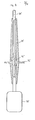
- Fig. 4 shows a paddle or spoon-shaped electrode which can be applied directly to the heart muscle.
- This electrode has an application electrode 30 in the form of a spoon or paddle, which is attached to the heart muscle for internal use during defibrillation.
- a circumferential protective electrode 32 is provided, which has a bushing 35 for the supply line.
- both the supply line for the application electrode 30 and the line connected to the protective electrode 32 are at the front. term operating handle 31 led away.
- These lines can be connected in the same manner as is shown in the exemplary embodiments in FIGS. 1 to 3.
- FIG. 5 shows an exemplary embodiment for an energy store 1 and a work switch 6 of the defibrillator circuit 37.
- the energy store 1 consists of several capacitors C ... C connected in series.
- the work switch 6 has several even-1 n if switches Sb ... Sb connected in series, 1 n the connection points of two capacitors C1 and C2 ... C n -1 and C n with the connection points of two switches Sb and Sb. ..Sb - 1 and Sb connected 1 2 nn are connected via further switches Sa 1 ... Sa n .
- the capacitors connected in series are all charged to the same voltage level.
- the capacitors are discharged one after the other in precisely defined time periods.
- the switches Sb ... Sb are closed in succession in these defined time periods.
- the respective switch Sa ... Sa via which the previous discharge of a respective capacitor was carried out, is opened.
- the capacitor C is first discharged via the closed switch Sa and the closed switch 1 Sb.
- the switches Sb ... Sb are open.
- To discharge the capacitor C the switch Sb is closed and the switch Sa is opened.
- Switch 1 Sb remains closed.
- Switch Sa is also closed. This means that the capacitor C 2 is discharged via the switch Sa, Sb, Sb.
- the remaining capacitors C ... C are discharged in the same way.
- the switches Sb ... Sb are open before the capacitor 3 n gates begin to discharge. 1 n
- the switches Sa ... Sa can be closed. 1 n
- the energy store consists of connected in parallel Capacitors C ... C.
- the capacitors 1 n are charged via a charging line 33 with switches 1 n SL ... SL connected in series with the capacitors C ... C.
- the discharge takes place via a discharge line 34, the switches SL ... SL open and the 1 n switches SE ... SE, which are in series with the capacitors C ... C, in succession at certain times stands will be closed.
- an individually desired discharge curve is formed by successively increasing the individual capacitor voltages with simultaneous discharge via the shock electrodes.
- the switches SE ... SE assume the function of the working switch 6. Diodes, transistors, thyristo-1 are also suitable for the switches SL ... SL and 1 n SE ... SE n ren and the like
Landscapes
- Health & Medical Sciences (AREA)
- Cardiology (AREA)
- Heart & Thoracic Surgery (AREA)
- Engineering & Computer Science (AREA)
- Biomedical Technology (AREA)
- Nuclear Medicine, Radiotherapy & Molecular Imaging (AREA)
- Radiology & Medical Imaging (AREA)
- Life Sciences & Earth Sciences (AREA)
- Animal Behavior & Ethology (AREA)
- General Health & Medical Sciences (AREA)
- Public Health (AREA)
- Veterinary Medicine (AREA)
- Electrotherapy Devices (AREA)
Priority Applications (1)
| Application Number | Priority Date | Filing Date | Title |
|---|---|---|---|
| AT84109215T ATE34304T1 (de) | 1983-08-03 | 1984-08-03 | Elektrische schockelektrodenschaltung fuer einen defibrillator. |
Applications Claiming Priority (2)
| Application Number | Priority Date | Filing Date | Title |
|---|---|---|---|
| US51984383A | 1983-08-03 | 1983-08-03 | |
| US519843 | 1983-08-03 |
Publications (2)
| Publication Number | Publication Date |
|---|---|
| EP0135735A1 true EP0135735A1 (fr) | 1985-04-03 |
| EP0135735B1 EP0135735B1 (fr) | 1988-05-18 |
Family
ID=24070030
Family Applications (1)
| Application Number | Title | Priority Date | Filing Date |
|---|---|---|---|
| EP84109215A Expired EP0135735B1 (fr) | 1983-08-03 | 1984-08-03 | Circuit d'électrode de choc électrique pour un défibrillateur |
Country Status (3)
| Country | Link |
|---|---|
| EP (1) | EP0135735B1 (fr) |
| AT (1) | ATE34304T1 (fr) |
| DE (1) | DE3471258D1 (fr) |
Cited By (4)
| Publication number | Priority date | Publication date | Assignee | Title |
|---|---|---|---|---|
| EP0445800A1 (fr) * | 1990-03-07 | 1991-09-11 | Müller, Gerhard | Circuit électrique pour mettre à la disposition des impulsions à haute tension, particulièrement pour défibrillateurs |
| AU621839B2 (en) * | 1988-04-11 | 1992-03-26 | Fukuda Denshi Co., Ltd. | Electrode for use with a defibrillator |
| EP0691870A4 (fr) * | 1993-03-31 | 1996-06-05 | Survivalink Corp | Mecanisme de prevention des courants de fuite pour circuit de defibrillation |
| EP3772361A1 (fr) * | 2019-08-06 | 2021-02-10 | BIOTRONIK SE & Co. KG | Générateur d'impulsions pouvant être implanté à ondes rectangulaires |
Families Citing this family (1)
| Publication number | Priority date | Publication date | Assignee | Title |
|---|---|---|---|---|
| DE4110402A1 (de) * | 1991-03-28 | 1992-10-01 | Siemens Ag | Defibrillator/konverter |
Citations (5)
| Publication number | Priority date | Publication date | Assignee | Title |
|---|---|---|---|---|
| US3196877A (en) * | 1962-11-14 | 1965-07-27 | Corbin Farnsworth Inc | Defibrillation electrode device |
| US3389703A (en) * | 1966-02-03 | 1968-06-25 | Zenith Radio Corp | Defibrillator electrode or the like |
| GB1298189A (en) * | 1970-02-09 | 1972-11-29 | Medtronic Inc | Electromedical apparatus |
| US3942533A (en) * | 1974-10-17 | 1976-03-09 | Cannon Robert L Iii | Cardiac defibrillator depolarizing paddle arrangement |
| DE2811325A1 (de) * | 1978-03-16 | 1979-09-27 | Messerschmitt Boelkow Blohm | Fibrillator fuer herzchirurgie |
-
1984
- 1984-08-03 DE DE8484109215T patent/DE3471258D1/de not_active Expired
- 1984-08-03 AT AT84109215T patent/ATE34304T1/de not_active IP Right Cessation
- 1984-08-03 EP EP84109215A patent/EP0135735B1/fr not_active Expired
Patent Citations (5)
| Publication number | Priority date | Publication date | Assignee | Title |
|---|---|---|---|---|
| US3196877A (en) * | 1962-11-14 | 1965-07-27 | Corbin Farnsworth Inc | Defibrillation electrode device |
| US3389703A (en) * | 1966-02-03 | 1968-06-25 | Zenith Radio Corp | Defibrillator electrode or the like |
| GB1298189A (en) * | 1970-02-09 | 1972-11-29 | Medtronic Inc | Electromedical apparatus |
| US3942533A (en) * | 1974-10-17 | 1976-03-09 | Cannon Robert L Iii | Cardiac defibrillator depolarizing paddle arrangement |
| DE2811325A1 (de) * | 1978-03-16 | 1979-09-27 | Messerschmitt Boelkow Blohm | Fibrillator fuer herzchirurgie |
Cited By (8)
| Publication number | Priority date | Publication date | Assignee | Title |
|---|---|---|---|---|
| AU621839B2 (en) * | 1988-04-11 | 1992-03-26 | Fukuda Denshi Co., Ltd. | Electrode for use with a defibrillator |
| EP0445800A1 (fr) * | 1990-03-07 | 1991-09-11 | Müller, Gerhard | Circuit électrique pour mettre à la disposition des impulsions à haute tension, particulièrement pour défibrillateurs |
| EP0691870A4 (fr) * | 1993-03-31 | 1996-06-05 | Survivalink Corp | Mecanisme de prevention des courants de fuite pour circuit de defibrillation |
| EP3772361A1 (fr) * | 2019-08-06 | 2021-02-10 | BIOTRONIK SE & Co. KG | Générateur d'impulsions pouvant être implanté à ondes rectangulaires |
| WO2021023506A1 (fr) * | 2019-08-06 | 2021-02-11 | Biotronik Se & Co. Kg | Générateur d'impulsions implantable ayant une forme d'onde de choc rectangulaire |
| CN114096307A (zh) * | 2019-08-06 | 2022-02-25 | 百多力两合公司 | 具有矩形电击波形的可植入脉冲发生器 |
| US12337186B2 (en) | 2019-08-06 | 2025-06-24 | Biotronik Se & Co. Kg | Implantable pulse generator having rectangular shock waveform |
| CN114096307B (zh) * | 2019-08-06 | 2026-04-24 | 百多力两合公司 | 具有矩形电击波形的可植入脉冲发生器 |
Also Published As
| Publication number | Publication date |
|---|---|
| ATE34304T1 (de) | 1988-06-15 |
| EP0135735B1 (fr) | 1988-05-18 |
| DE3471258D1 (en) | 1988-06-23 |
Similar Documents
| Publication | Publication Date | Title |
|---|---|---|
| EP0569609B1 (fr) | Système de défibrillateur implantable | |
| DE69825568T2 (de) | Externer defibrillator mit h-brückenschaltung zur erzeugung einer zweiphasigen wellenform hoher energie | |
| EP1062969B1 (fr) | Ensemble électrode | |
| DE718637C (de) | Einrichtung zur Spulenfeldbehandlung mit kurzwelligen elektrischen Schwingungen | |
| DE3884692T2 (de) | Defibrillator. | |
| DE68925218T2 (de) | Verfahren und Apparat zur Anwendung von asymmetrischen, zweiphasigen, abgeschnittenen exponentiellen Gegenschocks | |
| EP0574609A1 (fr) | Defibrillateur/cardioverteur | |
| EP0445800A1 (fr) | Circuit électrique pour mettre à la disposition des impulsions à haute tension, particulièrement pour défibrillateurs | |
| DE2651031A1 (de) | Medizinisches geraet zur elektroschockbehandlung | |
| EP0135735B1 (fr) | Circuit d'électrode de choc électrique pour un défibrillateur | |
| DE2444893A1 (de) | Schaltungsanordnung zum zuenden mindestens einer gasentladungs-blitzlichtlampe | |
| EP3772361A1 (fr) | Générateur d'impulsions pouvant être implanté à ondes rectangulaires | |
| DE2646277A1 (de) | Schaltungsanordnung zum steuern des durchgangs von elektrischen signalen | |
| DE1803212C3 (de) | Schaltungsanordnung für eine alternativ als Motor oder Generator arbeitende elektrische Maschine | |
| EP0071965B2 (fr) | Stimulateur cardiaque implantable (sûreté d'une amplitude minimale) | |
| CH661383A5 (de) | Thyristoreinrichtung. | |
| DE3910741A1 (de) | Hochspannungsrelaisschaltung | |
| DD147317A1 (de) | Einrichtung zur elektrischen stimulation des herzens | |
| DE3109489A1 (de) | Defibrillator | |
| EP0269846A1 (fr) | Stimulateur | |
| DE2813110A1 (de) | Elektromotorisch angetriebenes geraet mit funkentstoerung | |
| DE2338540A1 (de) | In einem herzschrittmacher verwendbarer impulsgenerator, der impulse mit konstanter energie erzeugt | |
| DE2649474A1 (de) | Reizstromgenerator | |
| DE1947482C3 (de) | Maschine zum Kondensatorimpulsschweißen | |
| DE1513726A1 (de) | Anordnung zur UEberwachung der Speisung eines mehrphasigen Verbrauchers |
Legal Events
| Date | Code | Title | Description |
|---|---|---|---|
| PUAI | Public reference made under article 153(3) epc to a published international application that has entered the european phase |
Free format text: ORIGINAL CODE: 0009012 |
|
| AK | Designated contracting states |
Designated state(s): AT CH DE FR GB IT LI |
|
| 17P | Request for examination filed |
Effective date: 19850906 |
|
| 17Q | First examination report despatched |
Effective date: 19870415 |
|
| GRAA | (expected) grant |
Free format text: ORIGINAL CODE: 0009210 |
|
| AK | Designated contracting states |
Kind code of ref document: B1 Designated state(s): AT CH DE FR GB IT LI |
|
| REF | Corresponds to: |
Ref document number: 34304 Country of ref document: AT Date of ref document: 19880615 Kind code of ref document: T |
|
| REF | Corresponds to: |
Ref document number: 3471258 Country of ref document: DE Date of ref document: 19880623 |
|
| ET | Fr: translation filed | ||
| GBT | Gb: translation of ep patent filed (gb section 77(6)(a)/1977) | ||
| ITF | It: translation for a ep patent filed | ||
| PLBE | No opposition filed within time limit |
Free format text: ORIGINAL CODE: 0009261 |
|
| STAA | Information on the status of an ep patent application or granted ep patent |
Free format text: STATUS: NO OPPOSITION FILED WITHIN TIME LIMIT |
|
| 26N | No opposition filed | ||
| ITTA | It: last paid annual fee | ||
| PGFP | Annual fee paid to national office [announced via postgrant information from national office to epo] |
Ref country code: GB Payment date: 19940802 Year of fee payment: 11 |
|
| PGFP | Annual fee paid to national office [announced via postgrant information from national office to epo] |
Ref country code: FR Payment date: 19940812 Year of fee payment: 11 |
|
| PGFP | Annual fee paid to national office [announced via postgrant information from national office to epo] |
Ref country code: AT Payment date: 19940831 Year of fee payment: 11 |
|
| PGFP | Annual fee paid to national office [announced via postgrant information from national office to epo] |
Ref country code: CH Payment date: 19941129 Year of fee payment: 11 |
|
| PG25 | Lapsed in a contracting state [announced via postgrant information from national office to epo] |
Ref country code: GB Effective date: 19950803 Ref country code: AT Effective date: 19950803 |
|
| PG25 | Lapsed in a contracting state [announced via postgrant information from national office to epo] |
Ref country code: LI Effective date: 19950831 Ref country code: CH Effective date: 19950831 |
|
| GBPC | Gb: european patent ceased through non-payment of renewal fee |
Effective date: 19950803 |
|
| REG | Reference to a national code |
Ref country code: CH Ref legal event code: PL |
|
| PG25 | Lapsed in a contracting state [announced via postgrant information from national office to epo] |
Ref country code: FR Effective date: 19960430 |
|
| REG | Reference to a national code |
Ref country code: FR Ref legal event code: ST |
|
| PGFP | Annual fee paid to national office [announced via postgrant information from national office to epo] |
Ref country code: DE Payment date: 20001031 Year of fee payment: 17 |
|
| PG25 | Lapsed in a contracting state [announced via postgrant information from national office to epo] |
Ref country code: DE Free format text: LAPSE BECAUSE OF NON-PAYMENT OF DUE FEES Effective date: 20020501 |