EP0135745A2 - Festmembran für einen Indikatorraum - Google Patents
Festmembran für einen Indikatorraum Download PDFInfo
- Publication number
- EP0135745A2 EP0135745A2 EP84109281A EP84109281A EP0135745A2 EP 0135745 A2 EP0135745 A2 EP 0135745A2 EP 84109281 A EP84109281 A EP 84109281A EP 84109281 A EP84109281 A EP 84109281A EP 0135745 A2 EP0135745 A2 EP 0135745A2
- Authority
- EP
- European Patent Office
- Prior art keywords
- membrane
- arrangement according
- indicator
- polymer
- percent
- Prior art date
- Legal status (The legal status is an assumption and is not a legal conclusion. Google has not performed a legal analysis and makes no representation as to the accuracy of the status listed.)
- Granted
Links
Images


Classifications
-
- G—PHYSICS
- G01—MEASURING; TESTING
- G01N—INVESTIGATING OR ANALYSING MATERIALS BY DETERMINING THEIR CHEMICAL OR PHYSICAL PROPERTIES
- G01N21/00—Investigating or analysing materials by the use of optical means, i.e. using sub-millimetre waves, infrared, visible or ultraviolet light
- G01N21/62—Systems in which the material investigated is excited whereby it emits light or causes a change in wavelength of the incident light
- G01N21/63—Systems in which the material investigated is excited whereby it emits light or causes a change in wavelength of the incident light optically excited
- G01N21/64—Fluorescence; Phosphorescence
- G01N21/6428—Measuring fluorescence of fluorescent products of reactions or of fluorochrome labelled reactive substances, e.g. measuring quenching effects, using measuring "optrodes"
- G01N21/643—Measuring fluorescence of fluorescent products of reactions or of fluorochrome labelled reactive substances, e.g. measuring quenching effects, using measuring "optrodes" non-biological material
-
- G—PHYSICS
- G01—MEASURING; TESTING
- G01N—INVESTIGATING OR ANALYSING MATERIALS BY DETERMINING THEIR CHEMICAL OR PHYSICAL PROPERTIES
- G01N21/00—Investigating or analysing materials by the use of optical means, i.e. using sub-millimetre waves, infrared, visible or ultraviolet light
- G01N21/62—Systems in which the material investigated is excited whereby it emits light or causes a change in wavelength of the incident light
- G01N21/63—Systems in which the material investigated is excited whereby it emits light or causes a change in wavelength of the incident light optically excited
- G01N21/64—Fluorescence; Phosphorescence
- G01N21/6428—Measuring fluorescence of fluorescent products of reactions or of fluorochrome labelled reactive substances, e.g. measuring quenching effects, using measuring "optrodes"
- G01N2021/6434—Optrodes
Definitions
- the invention relates to a solid membrane for delimiting an indicator space which has an optically measurable fluorescent indicator which can be optically changed by the concentration of a substance or by a physical or chemical parameter.
- the indicator spaces of the designated genus represent the essential part of measuring devices that optically determine the concentration or the physical or chemical parameters.
- Such measuring devices irradiate the measuring object with monochromatic test light, measure the light emanating from the indicator, the measuring light, with a light measuring device and then display the parameter or the concentration of the substance that triggered this change.
- the solid membrane forms the indicator space, the indicator is polymerized or sealed into the membrane.
- the optodes used should be designed in such a way that the most accurate measurement possible can be carried out.
- Kl 3.8 * 10exp-2 (pyrene butyric acid in silicone membrane)
- K2 2.4 * 10exp-3 (pyrene butyric acid in dioctyl phthalate) can be formed.
- the functions (2) intersect at an intersection point S (M) at about 105 mmHg oxygen partial pressure, high sensitivity for large concentrations being found for small concentrations, high sensitivity for small concentrations for small concentrations.
- the invention has therefore set itself the task of optimizing the measuring arrangement by setting the K value.
- the indicator being embedded in a membrane which consists of a mixture of at least two polymers and by the working point of the membrane being set by the mixing ratio of the two polymers.
- the advantage of this arrangement is that the optode can now be set so that measurements can be carried out with high sensitivity either at low oxygen concentrations or that measurements can be carried out over the entire range with approximately the same measurement sensitivity.
- the indicator space has a spatially variable K value.
- Such an arrangement has the advantage that the membrane area is brought into active connection with the measurement object with the appropriate K value and through that Light measuring device can be measured.
- the polymer mixture consists of silicone polymer and PVC polymer.
- the measuring sensitivity can be increased over that with pure polymer membranes if the mixing ratio is in the range between 5-30 percent by weight PVC polymer in 95-70 percent by weight silicone polymer.
- a reduction in the K value occurs when mixtures of silicone polymer and PoLystyroL are made.
- the total quench constant K is a measure of the parameter sensitivity of the optode.
- the term "quench" constant arises because the particles - depending on the indicator oxygen molecules or other particle types to be measured - reduce the fluorescence of the indicator molecules by quenching the excited states of the indicator molecules.
- the quench constant is determined from the mean lifetime of the excited state of the indicator molecule, the collision quench constant K * and the solubility coefficient S.
- the constant K can be influenced independently of the substance parameters by selecting the plastic matrices in which the indicator molecules are embedded.
- the constant K1 is obtained by introducing the indicator into a matrix made of silicone rubber
- the constant K2 is obtained by introducing the same indicator into a matrix made of dioctyl phthalate.
- the K values can be freely set by using polymer mixtures for the membrane representing the indicator space instead of single-component membranes.
- polymer mixtures made of polymeric silicone rubber and polymeric PVC can be used in a ratio of 5-30 percent by weight PVC polymer in 95-70 Weight percent silicone polymer can achieve a variation in the K values of a fluorescent indicator by a factor of 2.
- a gradient of the mixing ratio can also be generated over an optode surface 33. Then, for example, by shifting the optode 33 in the direction 38 in a fluorometer consisting of a monochromatic radiator 1 and a monochromatic receiver 2 with display A and a measuring chamber for a measurement object G, the K value of the optode 33 can be set which has the smallest possible noise amps Has operating point.
- the optode 33 is shifted in the beam path 37 in the direction 38 until the fluctuations on the display A reach a minimum. This is particularly noticeable with digital displays A because a Shifting the fluctuating display decade to the right is no longer possible.
- the measuring spot can also be moved on a fixed optode.
- the membranes according to the invention can be provided with further indicators whose indicator wavelengths are different from one another. After separation of the signals assigned to the individual indicators, this enables measurement of different particle fractions or of different chemical or physical parameters.
- One of the other indicators can also be designed as a reference indicator. With the help of the reference indicator, the signal of which does not depend on the particles or parameters to be measured and which is used to form quotients with parameter-dependent signals, a display signal that is independent of optical or electrical changes to the apparatus can be obtained.
- the membranes according to the invention can furthermore be optically decoupled from the measurement object, for example by pigment incorporation, so that interference with the measurement radiation by the measurement object is minimized.
- the known solubilizations for the starting materials can be used both for the polymers to be mixed and for the indicators to be added.
Landscapes
- Health & Medical Sciences (AREA)
- Immunology (AREA)
- Life Sciences & Earth Sciences (AREA)
- Physics & Mathematics (AREA)
- Chemical & Material Sciences (AREA)
- Nuclear Medicine, Radiotherapy & Molecular Imaging (AREA)
- Chemical Kinetics & Catalysis (AREA)
- Optics & Photonics (AREA)
- Molecular Biology (AREA)
- Analytical Chemistry (AREA)
- Biochemistry (AREA)
- General Health & Medical Sciences (AREA)
- General Physics & Mathematics (AREA)
- Pathology (AREA)
- Investigating Or Analysing Materials By The Use Of Chemical Reactions (AREA)
- Separation Using Semi-Permeable Membranes (AREA)
- Investigating, Analyzing Materials By Fluorescence Or Luminescence (AREA)
Abstract
Description
- Die Erfindung betrifft eine Festmembran zur Begrenzung eines Indikatorraums, der einen optisch vermessbaren, durch die Konzentration einer Substanz oder durch einen physikalischen oder chemischen Parameter optisch veränderbaren FLuoreszenzindikator aufweist.
- Die Indikatorräume der bezeichneten Gattung, häufig OPTODEN genannt, stellen den wesentlichen TeiL von Messeinrichtungen dar, die optisch die Konzentration oder den physikalischen oder chemischen Parameter bestimmen. SoLche Messeinrichtungen bestrahlen das Messobjekt mit monochromatischem Prüflicht, messen mit einer Lichtmesseinrichtung das vom Indikator ausgehende Licht, das Messlicht, und zeigen danach den Parameter oder die Konzentration der Substanz an, die diese Änderung ausgelöst hat.
- Die Festmembran bildet dabei den Indikatorraum, der Indikator ist in die Membran einpolymerisiert oder eingesiegelt.
- Die verwendeten Optoden sollen derart ausgebildet sein, dass eine möglichst genaue Messung vorgenommen werden kann.
- Die MessempfindLichkeit von Optoden, deren Indikatoren Fluoreszenzlicht aussenden und die auf Teilchenkonzentrationen reagieren, wirft dabei besondere ProbLeme auf.
- Nach STERN-VOLLMER hängt die Fluoreszenzlöschung von FLuoreszenzindikatoren durch Einwirkung der zu messenden TeiLchen auf den Indikator hyperbolisch von der Teilchenkonzentration ab. Es ist beispielsweise für SauerstoffmoLeküLe

- P(O2)=Sauerstoffpartialdruck
- Io =Fluoreszenzintensität ohne TeiLchen
- Durch Ableitung der Funktion nach P erhält man die eine MessempfindLichkeit beschreibende Funktion S(P) mit
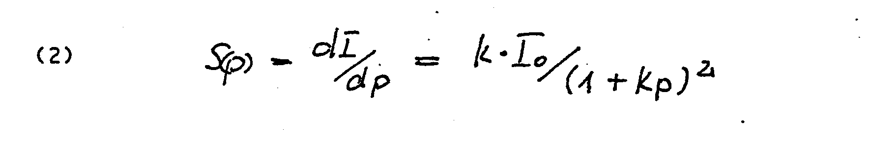
- Für unterschiedliche Konstanten K ergeben sich Hyperbelscharen S(P), die sich im Bereich grosser Teilchenkon=entrationen schneiden. Ein Beispiel dafür sind etwa die Funktionen S(P), die aus den beiden K-Werten
- Kl=3.8*10exp-2 (Pyrenbuttersäure in Siliconmembran) K2=2.4*10exp-3 (Pyrenbuttersäure in Dioctylphtalat) gebildet werden können.
- Für dieseK-Werte Schneiden sich die Funktionen (2) in einem Schnittpunkt S(M) bei etwa 105 mmHg Sauerstoffpartialdruck, wobei für kleine Konzentrationen hohe MessempfindLichkeiten bei grossen K-Werten, für grosse Konzentrationen hohe Messempfindlichkeiten bei kleinen K-Werten gefunden werden.
- Es sollte danach im Konzentrationsbereich oberhalb des Schnittpunktes S mit grösseren K-Werten, im Konzentrationsbereich unterhalb des Schnittpunktes S mit kleineren K-Werten gearbeitet werden.
- Die Optimierung der Messanordnung durch EinsteLLung des K-Wertes hat sich die Erfindung deshalb zur Aufgabe gemacht.
- Sie Löst diese Aufgabe dadurch, dass der Indikator in eine Membran eingebettet ist, die aus einer Mischung aus mindestens zwei PoLymeren besteht und dass der Arbeitspunkt der Membran durch das MischungsverhäLtnis der beiden PoLymere eingestellt ist.
- Der Vorteil dieser Anordnung Liegt darin, dass nunmehr die Optode so eingestellt werden kann, dass entweder bei kleinen Sauerstoffkonzentrationen mit hoher EmpfindLichkeit gemessen werden oder dass bei grossen Sauerstoffkonzentrationen über den gesamten Bereich mit etwa gleicher MessempfindLichkeit gemessen werden kann.
- Auch andere EinsteLLungen sind möglich.
- In Weiterbildung der Erfindung weist der Indikatorraum einen räumlich veränderlichen K-Wert auf.
- Eine solche Anordnung hat den Vorteil, dass der Membranbereich mit, dem jeweils passenden K-Wert in Wirkverbindung mit dem Messobjekt gebracht und durch die Lichtmesseinrichtung vermessen werden kann.
- Besonders gute Ergebnisse Lassen sich erzielen, wenn die Polymermischung aus Silicon-Polymer und PVC-Polymer besteht.
- Insbesondere Lässt sich die MessempfindLichkeit über diejenige mit reinen Polymermembranen steigern, wenn das MischungsverhäLtnis im Bereich zwischen 5-30 Gewichtsprozent PVC-PoLymer in 95-70 Gewichtsprozent Silicon-Polymer besteht.
- Eine Verringerung des K-Wertes tritt ein, wenn Mischungen aus Silicon-Polymer und PoLystyroL vorgenommen werden.
- Es ist somit möglich, den K-Wert über weite Bereiche durch entsprechende StoffwahL bei der Mischung der Komponenten zu ändern.
- Zur weiteren ErLäuterung der Erfindung zeigen in der Zeichnung die
- Fig.1: die EmpfindLichkeit von Fluorszenzoptoden bei Verwendung unterschiedlicher Matrices,
- Fig.2: den EmpfindLichkeitsbereich bei Änderungen des PVC-AnteiLs der Potymermischung.
- Fig.3: ein FLuorometer mit einer Optode mit räumlich variablem MischungsverhäLtnis und entsprechendem räumlich variablen K-Wert
- Für Fluoreszenzindikatoren gilt die STERN-VOLLMER-Gleichung .

- Io = Intensität ohne Einwirkung des Parameters
- [(p)= Intensität nach Einwirkung des Parameters
- = Gesamtquenchkonstante
- Die Gesamtquenchkonstante K ist dabei ein Mass für die ParameterempfindLichkeit der Optode. Die Bezeichnung "Quench"konstante ergibt sich, weil die TeiLchen -je nach Indikator Sauerstoffmoleküle oder andere zu messende Teilchenarten- die FLuoreszenz der Indikatormoleküle verringern, indem sie die angeregten Zustände der Indikatormoleküle Löschen.
- Aus Gl. (1) ergibt sich die MessempfindLichkeit dann zu
-


- K* beschreibt dabei die Anzahl der Kollisionen zwischen Indikatormolekülen und Sauerstoffmolekülen und bestimmt sich aus

- mit f = Effektivität der Kellisionen
- α = Summe der Radien der Stossmoleküle
- D= Summe der Diffusionskoeffizienten
- N = Molekülzahl / mmol
- Die Messempfindlichkeit lässt sich danach über die Wahl der verschiedenen Parameter verändern. Sie wird zunächst möglich gross gewählt, sollte dann aber auf den jeweils gewählten Messbereich abgestimmt werden. Wie nämlich Fig.1 zeigt, ist für grosse Konstanten K1 (K1=3.8*10exp-2/Torr) die MessempfindLickeit im unteren Konzentrationsbereich «100mmHg p02) gross, für kleine Konstanten K2 (K2=2.4*10exp-3/Torr) ist sie im oberen Konzentrationsbereich (>100mmHG p02) gross.
- Eine von den Stoffparametern unabhängige BeeinfLussung der Konstanten K Lässt sich durch die Wahl der Kunststoffmatrices erreichen, in denen die Indikatormoleküle eingebettet sind.
- Dabei hat sich gezeigt, dass sich der K-Wert und damit die die MessempfindLichkeit für einen vorgegeben Bereich je nach Wahl der Matrix vergrössern oder verkleinern Lässt.
- Wie Fig.2 beispielsweise zeigt, ergibt sich die Konstante K1 durch Einbringen des Indikators in eine Matrix aus Siliconkautschuk, die Konstante K2 durch Einbringen des gleichen Indikators in eine Matrix aus Dioctylphtalat.
- Eine freie EinsteLLbarkeit der K-Werte wird jedoch dadurch erreicht, dass anstelle von Einstoffmembranen solche aus PoLymermischungen für die den Indikatorraum darstellende Membran verwendet werden.
- Wie aus Fig.2 hervorgeht, Lässt sich bei PoLymermischungen aus polymeren SiLiconkautschuk und polymerem PVC in einem VerhäLtnis von 5-30 Gewichtsprozenten PVC-PoLymer in 95-70 Gewichtsprozenten Silicon-Polymer eine Variation der K-Werte eines FLuoreszenzindikators um etwa einen Faktor 2 erreichen.
- Da eine VerkLeinerung des K-Wertes, beispielsweise durch Mischung von Silicon-Polymer und PoLystyroL, ohne weiters erreichbar ist, ist es möglich den Arbeitspunkt der Optode durch einfache Wahl von Stoffmischungen und des MischungsverhäLtnisses zu verändern und auf den jeweiligen Messbereich anpassen.
- Der ZahLenwert für die anzustrebenden Gesamtquenchkonstante K beim Messwert P ergibt sich aus theoretischen Erwägungen zu

- K = Gesamtquenchkonstante
- SNRo= Signal/Rauschverhältnis des FLuorometers bei EndausschLag
- Δp= zugelassene Signalschwankung
- Insbesondere kann nach Fig.3 auch ein Gradient des Mischungsverhältnisses über eine Optodenfläche 33 erzeugt werden. Dann kann beispielsweise durch Verschiebung der Optode 33 in Richtung 38 in einem aus einem monochromasierten StrahLer 1 und einem monochromasierten Empfänger 2 mit Anzeige A und einer Messkammer für ein Messobjekt G bestehenden Fluorometer derjenige K-Wert der Optode 33 eingestellt werden, der möglichst kleine Rauschamptituden am Arbeitspunkt aufweist.
- Die Optode 33 wird dazu solange im StrahLengang 37 in Richtung 38 verschoben, bis die Schwankungen an der Anzeige A ein Minimum erreichen. Das ist insbesondere bei DigitaLanzeigen A Leicht dadurch feststellbar, dass eine Verschiebung der jeweils schwankenden Anzeigedekade nach rechts nicht mehr möglich ist.
- AnsteLLe der Optode kann auch der Messfleck auf einer festliegenden Optode verschoben werden.
- Die erfindungsgemässen Membranen können mit weiteren Indikatoren versehen sein, deren Indikatorwellenlänge verschieden untereinander sind. Dadurch ist nach Separation der den einzelnen Indikatoren zugeordneten SignaLen eine Messung von unterschiedlichen TeiLchenfraktionen oder von verschiedenen chemischen oder physikalischen Parametern ermöglicht. Einer der weiteren Indikatoren kann auch als Referenzindikator ausgebildet sein. Mit HiLfe des Referenzindikators, dessen SignaL nicht von den zu messenden TeiLchen oder Parameteren abhängt und das zur QuotientenbiLdung mit parameterabhängigen SignaLen herangezogen wird, kann ein von optischen oder elektrischen Änderungen der Apparatur unabhängiges Anzeigesignal gewonnen werden.
- Die erfindungsgemässen Membranen können weiterhin, beispielsweise durch Pigmenteinlagerungen, optisch vom Messobjekt entkoppelt sein, sodass Störungen der Messtrahlung durch das Messobjekt minimiert sind.
- Bei der HersteLLung der Membranen können sowohl für die zu mischenden PoLymere als auch für die zuzufügenden Indikatoren die bekannten Solubilisierungen für die Ausgangsstoffe verwendet werden.
Claims (13)
gekennzeichnet,
dass der Indikator in eine Membran eingebettet ist, die aus einer Mischung von mindestens zwei PoLymeren besteht und dass der Arbeitspunkt der Membran durch das MischungsverhäLtnis der beiden PoLymere eingestellt ist.

Priority Applications (1)
| Application Number | Priority Date | Filing Date | Title |
|---|---|---|---|
| AT84109281T ATE41235T1 (de) | 1983-08-12 | 1984-08-04 | Festmembran fuer einen indikatorraum. |
Applications Claiming Priority (2)
| Application Number | Priority Date | Filing Date | Title |
|---|---|---|---|
| DE3329461 | 1983-08-12 | ||
| DE19833329461 DE3329461A1 (de) | 1983-08-12 | 1983-08-12 | Festmembran fuer einen indikatorraum |
Publications (3)
| Publication Number | Publication Date |
|---|---|
| EP0135745A2 true EP0135745A2 (de) | 1985-04-03 |
| EP0135745A3 EP0135745A3 (en) | 1986-04-30 |
| EP0135745B1 EP0135745B1 (de) | 1989-03-08 |
Family
ID=6206599
Family Applications (1)
| Application Number | Title | Priority Date | Filing Date |
|---|---|---|---|
| EP84109281A Expired EP0135745B1 (de) | 1983-08-12 | 1984-08-04 | Festmembran für einen Indikatorraum |
Country Status (4)
| Country | Link |
|---|---|
| EP (1) | EP0135745B1 (de) |
| JP (1) | JPS6056243A (de) |
| AT (1) | ATE41235T1 (de) |
| DE (2) | DE3329461A1 (de) |
Cited By (3)
| Publication number | Priority date | Publication date | Assignee | Title |
|---|---|---|---|---|
| AU582947B2 (en) * | 1986-02-13 | 1989-04-13 | Howmedica Inc. | Fluorescent polymers |
| EP0300990A3 (de) * | 1987-07-20 | 1991-02-06 | AVL Medical Instruments AG | Deckschicht, vorzugsweise zur probenseitigen Anbringung an optischen Ionensensoren |
| WO1992010740A1 (de) * | 1990-12-12 | 1992-06-25 | Avl Medical Instruments Ag | Verfahren und vorrichtung zur kontinuierlichen und reversiblen messung der konzentration einer chemischen spezies |
Families Citing this family (1)
| Publication number | Priority date | Publication date | Assignee | Title |
|---|---|---|---|---|
| DE102021102505A1 (de) | 2020-12-21 | 2022-06-23 | Endress+Hauser Conducta Gmbh+Co. Kg | Optochemischer Sensor sowie Verfahren zum Messen von lumineszierenden Analyten in einem Messmedium |
Family Cites Families (5)
| Publication number | Priority date | Publication date | Assignee | Title |
|---|---|---|---|---|
| NL286850A (de) * | 1961-12-18 | 1900-01-01 | ||
| DE2856252A1 (de) * | 1978-12-27 | 1980-07-17 | Max Planck Gesellschaft | Membranen fuer indikatorraeume |
| DE3219397A1 (de) * | 1982-05-24 | 1983-11-24 | Max Planck Gesellschaft zur Förderung der Wissenschaften e.V., 3400 Göttingen | Anordnung zur optischen messung von konzentrationen |
| DE3369801D1 (en) * | 1982-10-06 | 1987-03-19 | Avl Ag | Measurement device for determining the carbon dioxide content of a sample |
| AT379688B (de) * | 1982-11-22 | 1986-02-10 | List Hans | Sensorelement zur bestimmung des o2-gehaltes einer probe |
-
1983
- 1983-08-12 DE DE19833329461 patent/DE3329461A1/de not_active Withdrawn
-
1984
- 1984-08-04 DE DE8484109281T patent/DE3477059D1/de not_active Expired
- 1984-08-04 EP EP84109281A patent/EP0135745B1/de not_active Expired
- 1984-08-04 AT AT84109281T patent/ATE41235T1/de not_active IP Right Cessation
- 1984-08-13 JP JP59167962A patent/JPS6056243A/ja active Pending
Cited By (3)
| Publication number | Priority date | Publication date | Assignee | Title |
|---|---|---|---|---|
| AU582947B2 (en) * | 1986-02-13 | 1989-04-13 | Howmedica Inc. | Fluorescent polymers |
| EP0300990A3 (de) * | 1987-07-20 | 1991-02-06 | AVL Medical Instruments AG | Deckschicht, vorzugsweise zur probenseitigen Anbringung an optischen Ionensensoren |
| WO1992010740A1 (de) * | 1990-12-12 | 1992-06-25 | Avl Medical Instruments Ag | Verfahren und vorrichtung zur kontinuierlichen und reversiblen messung der konzentration einer chemischen spezies |
Also Published As
| Publication number | Publication date |
|---|---|
| JPS6056243A (ja) | 1985-04-01 |
| DE3477059D1 (en) | 1989-04-13 |
| ATE41235T1 (de) | 1989-03-15 |
| DE3329461A1 (de) | 1985-02-21 |
| EP0135745A3 (en) | 1986-04-30 |
| EP0135745B1 (de) | 1989-03-08 |
Similar Documents
| Publication | Publication Date | Title |
|---|---|---|
| AT391949B (de) | Die optische messung von stoffkonzentrationen | |
| DE2923946C2 (de) | Vorrichtung zum Anzeigen der Teilchengrössenverteilung von strömenden Teilchenmengen in Fraktionsklassen | |
| DE68919892T2 (de) | Fluoreszenz-Mikroskopvorrichtung. | |
| EP0135101B1 (de) | Fluorimeter | |
| DE2225802C3 (de) | Verfahren nebst Vorrichtung zur Bestimmung der Konzentration eines Bestandteils in einem gasförmigen Probengemisch | |
| DE2632556C2 (de) | Lichtzuführung für eine Vorrichtung zur optischen Messung von Stoffkonzentrationen | |
| EP0109958A2 (de) | Messeinrichtung zur Bestimmung des 02-Gehaltes einer Probe | |
| DE3009835A1 (de) | Verfahren und vorrichtung zur bestimmung der eigenschaften eines segmentierten fluids, ohne in das fluid einzudringen | |
| DE3543324C2 (de) | ||
| EP1199556A1 (de) | Optischer Sensor zur Bestimmung eines Analyten und Verfahren zu dessen Herstellung | |
| DE3937141A1 (de) | Nichtdispersiver infrarot-gasanalysator zur gleichzeitigen messung der konzentration mehrerer komponenten einer gasprobe | |
| EP0144713A2 (de) | Anordnung zur optischen Messung von Stoffkonzentrationen | |
| WO1992010740A1 (de) | Verfahren und vorrichtung zur kontinuierlichen und reversiblen messung der konzentration einer chemischen spezies | |
| DE69223377T2 (de) | Spektralphotometer zur Ausführung turbidimetrischer und kolorimetrischer Messungen | |
| DE881877C (de) | Verfahren zur Zaehlung von in einem lichtdurchlaessigen Medium schwebenden Teilchen und Messgeraet zur Durchfuehrung des Verfahrens | |
| EP0135745B1 (de) | Festmembran für einen Indikatorraum | |
| DE2439413A1 (de) | Photometrisches verfahren zur quantitativen bestimmung eines stoffes in einer mischphase | |
| EP0353619A1 (de) | Verfahren und Vorrichtung zur Bestimmung von lokalen Farbstoff-Konzentrationen und von Streuparametern in tierischen und menschlichen Geweben | |
| DE2355148C3 (de) | Vorrichtung zur Untersuchung der Zusammensetzung einer strömenden FlUs- | |
| DE69415287T2 (de) | Verfahren zur isotopenanalyse mittels der optischen emissionsspektometrie eines durch laserenergie erzeugten plasma | |
| DE102013109010A1 (de) | Verfahren zur Bestimmung einer Veränderlichen einer Probe | |
| DE3731804A1 (de) | Anordnung zur bestimmung des dispersionsgrades magnetischer pigmente in einer dispersion | |
| DE2621216A1 (de) | Verfahren und vorrichtung zur untersuchung von puelpe auf das vorhandensein von verdickungen | |
| DE10149734B4 (de) | Gassensor und Verfahren zur Herstellung seiner Polymermatrix | |
| EP0095074B1 (de) | Anordnung zur optischen Messung von Konzentrationen |
Legal Events
| Date | Code | Title | Description |
|---|---|---|---|
| PUAI | Public reference made under article 153(3) epc to a published international application that has entered the european phase |
Free format text: ORIGINAL CODE: 0009012 |
|
| AK | Designated contracting states |
Designated state(s): AT CH DE FR GB IT LI LU NL SE |
|
| PUAL | Search report despatched |
Free format text: ORIGINAL CODE: 0009013 |
|
| AK | Designated contracting states |
Kind code of ref document: A3 Designated state(s): AT CH DE FR GB IT LI LU NL SE |
|
| 17P | Request for examination filed |
Effective date: 19860610 |
|
| 17Q | First examination report despatched |
Effective date: 19870519 |
|
| GRAA | (expected) grant |
Free format text: ORIGINAL CODE: 0009210 |
|
| AK | Designated contracting states |
Kind code of ref document: B1 Designated state(s): AT CH DE FR GB IT LI LU NL SE |
|
| PG25 | Lapsed in a contracting state [announced via postgrant information from national office to epo] |
Ref country code: SE Effective date: 19890308 Ref country code: NL Effective date: 19890308 Ref country code: IT Free format text: LAPSE BECAUSE OF FAILURE TO SUBMIT A TRANSLATION OF THE DESCRIPTION OR TO PAY THE FEE WITHIN THE PRESCRIBED TIME-LIMIT;WARNING: LAPSES OF ITALIAN PATENTS WITH EFFECTIVE DATE BEFORE 2007 MAY HAVE OCCURRED AT ANY TIME BEFORE 2007. THE CORRECT EFFECTIVE DATE MAY BE DIFFERENT FROM THE ONE RECORDED. Effective date: 19890308 |
|
| REF | Corresponds to: |
Ref document number: 41235 Country of ref document: AT Date of ref document: 19890315 Kind code of ref document: T |
|
| REF | Corresponds to: |
Ref document number: 3477059 Country of ref document: DE Date of ref document: 19890413 |
|
| GBT | Gb: translation of ep patent filed (gb section 77(6)(a)/1977) | ||
| ET | Fr: translation filed | ||
| PGFP | Annual fee paid to national office [announced via postgrant information from national office to epo] |
Ref country code: GB Payment date: 19890731 Year of fee payment: 6 |
|
| NLV1 | Nl: lapsed or annulled due to failure to fulfill the requirements of art. 29p and 29m of the patents act | ||
| PG25 | Lapsed in a contracting state [announced via postgrant information from national office to epo] |
Ref country code: LU Free format text: LAPSE BECAUSE OF NON-PAYMENT OF DUE FEES Effective date: 19890831 Ref country code: LI Effective date: 19890831 Ref country code: CH Effective date: 19890831 |
|
| PGFP | Annual fee paid to national office [announced via postgrant information from national office to epo] |
Ref country code: FR Payment date: 19890831 Year of fee payment: 6 |
|
| PGFP | Annual fee paid to national office [announced via postgrant information from national office to epo] |
Ref country code: AT Payment date: 19891206 Year of fee payment: 6 |
|
| PLBE | No opposition filed within time limit |
Free format text: ORIGINAL CODE: 0009261 |
|
| STAA | Information on the status of an ep patent application or granted ep patent |
Free format text: STATUS: NO OPPOSITION FILED WITHIN TIME LIMIT |
|
| 26N | No opposition filed | ||
| REG | Reference to a national code |
Ref country code: CH Ref legal event code: PL |
|
| PG25 | Lapsed in a contracting state [announced via postgrant information from national office to epo] |
Ref country code: DE Effective date: 19900501 |
|
| PG25 | Lapsed in a contracting state [announced via postgrant information from national office to epo] |
Ref country code: GB Effective date: 19900804 Ref country code: AT Effective date: 19900804 |
|
| GBPC | Gb: european patent ceased through non-payment of renewal fee | ||
| PG25 | Lapsed in a contracting state [announced via postgrant information from national office to epo] |
Ref country code: FR Effective date: 19910430 |
|
| REG | Reference to a national code |
Ref country code: FR Ref legal event code: ST |